RoboCupRescue 2011 - Robot League Team Red Knight RoboRescue Squad (USA)
Timothy E. Jump
Benilde-St. Margaret's School Advanced Competitive Science Program 2501 Hwy 100 S. St. Louis Park, MN USA 55416
Abstract Team RKRS is a component of a high school engineering program (Advanced Competitive Science) at Benilde-St. Margaret's School. The goal of the ACS program is to give students conceptual understanding in four engineering foundations (mechanical, electrical/electro-mechanical, design and control). Students that show extreme promise during their development of RoboCupJunior Rescue B robots are invited to contribute to and operate the team RKRS Robo-CupMajor Rescue Robot. As the controller on the ACS RoboCupJunior Rescue Robots is identical to the controller on the team RKRS RoboCupMajor Rescue Robot all the code students develop for their RCJ robots transfers and runs on the RCM robot. Ultimately, our participation at the RoboCupMajor level is an opportunity for the program leadership to demonstrate and integrate advanced engineering concepts and learning to the BSM-ACS students, and to participate and expose students to a true research project preparing them to enter into research positions as the enter their university studies. We also hope to produce functional products that can be implemented in higher level research projects and are commercially viable.
Introduction
Our focus is on development of advanced mobility, intuitively controlled, significantly cost effective robot transport systems. We are presenting a new concept design this year that minimizes driver control to one input action (computer mouse/point and click). The new design includes climbing arms set at a fixed position eliminating the complexity of arms that require driver managed control. We have also included rear abdominal belts so the robot has as much force transmitting surface area and a minimum amount of static lower structure that can hang on surfaces. We are also introducing a "toy" based drive system that is highly economical, with expectations that the complete transport system will be less than $1000 USD to produce in single lots and at a reduced cost in quantity. This is congruent with our continued efforts to produce disposable robots. We are also targeting full autonomy for navigation and victim identification with this new platform.
1. Team Members and Their Contributions
Engineering 3 Students/Seniors in the Benilde-St. Margaret's ACS Program participate across all of the following areas.
- Robot Locomotion (Mechanical and Electro-Mechanical)
- Robot Locomotion (Control)
- Navigation and Localization
- Victim Identification
- Map Generation
- Robotic Arm
- Operations
Students comprising the 2011 Benilde-St. Margaret's Rescue Major team:
Alex Smith Nils Swensen Margaret Murphy Catherine Coleman Tiana Press Jack Tift Chris Nagel Chris Monks Irena Cich
Advisor: Timothy Jump
2. Operator Station Set-up and Break-Down (3 minutes)
Setting up the team RKRS operator station is as simple as supplying power to the control console and switching it on. The control console has an integrated voltage converter, wifi router, antenna, control computer and monitor(s) as well as control device (mouse) and listening headset so it is an all-in-one control console solution.
Communication and application programs should start automatically upon boot saving time over computer boots where applications must be launched manually.
Operator station break-down is simply shutting down the control console and unplugging from the power source.
3. Communications
We have been exploring different communication protocols for the team RKRS robot. We have always used 5GHz, 802.11a communications in RoboCup competitions as per the rules, but 802.11a is very ineffective for non-line of sight (NLOS) applications as required in a true rescue situation. We have explored other ISM bands and found 900MHz LAN communications to be very effective in NLOS robot control, but 900MHz is only an open comm. protocol in Region 2 (USA). Other regions/countries have different open comm. frequencies so brining a 900MHz system to different regions could be an issue. We are exploring plug-n-play options to make the team RKRS robot internationally transferable, but there is limited development in high data rate LAN systems in these longer wavelength ISM bands.
We have also been researching open frequencies in the 2.4GHz range that are not 802.11, but again there is concern about interfering with other leagues if we use a 2.4GHz protocol.
Our current robot radio is a Lantronix Matchport 2.4GHz 802.11 b/g embedded wireless device server
The operator station uses a 2.4GHz 802.11 b/g Net Gear WNAP210 Wireless Access Point/Router
Table 1. Communication protocols under testing and available for use.
| Rescue Robot League | |||
|---|---|---|---|
| RKRS (USA) | |||
| Frequency | Channel/Band | Power (mW) | |
| 5.0 GHz - 802.11a | TBD | TBD | |
| 2.4 GHz - 802.11b/g | 6 channel options | 25.12mW | |
| 2.4 GHz - Other | 29 channel options | 10,000mW | |
| 900 MHz | 12 channel options | 4000mW |
4. Control Method and Human-Robot Interface
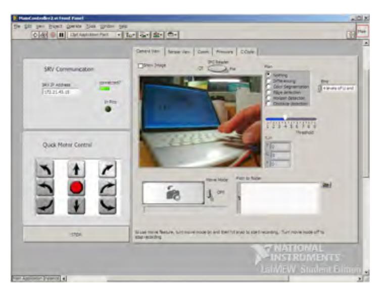
We can control the team RKRS robot through teleoperation via our custom LabVIEW control interface. From our MainCo ntroller2.vi we simply input the robot IP address and connect. Then we can drive motors, monitor sensors, monitor video and access video ana lysis protocols including horizon, edge, obstacle and motion (differencing) detection.
We can also switch the robot into autonomous mode via our La b-VIEW MainController2.vi by loading and executing picoC code.
We are currently developing an interactive function in our firmware that will allow for simultaneous running of autonomous functions and teleoperative controls.
We can also run remote vision autonomy with Robor ealm machine vision software running on the control console computer.
5. Map Generation
Mapping is accomplished by taking LIDAR scans. We are developing a low cost (sub $500 US), 360° scanning LIDAR which uses a Sharp analog IR distance ranging sensor and a Honeywell HMC6343 Digital Compass.
We use the compass to align our map scans to North, and the distance data to generate a point cloud we convert to graphical data in MS Excel. We overlay and align each map scan into a combined map output, then convert our MS Excel assembled map into a GeoTIFF file using Manifold Systems GIS software. We can then print the map or load it to a portable jump drive.
Victim placement is drag and drop from our mapping interface, with each drag and drop icon expandable to show victim data.
We are working on a mapping .vi for our LabVIEW control interface and hope to convert all mapping to a direct LabVIEW function.
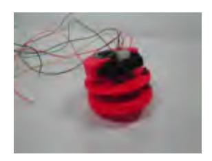
* If our custom LIDAR is not operational by competition time we will use a Hokuyo URG to generate our point cloud data for mapping
6. Sensors for Navigation and Localization
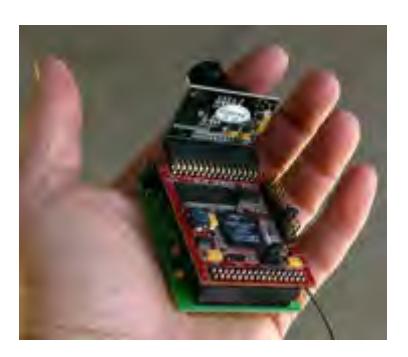
During teleoperation the primary sensor for navigation is the OmniVision OV7725 camera and our LabVIEW vision interface. From just the camera we get edge, horizon and obstacle detection.
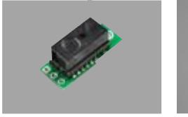
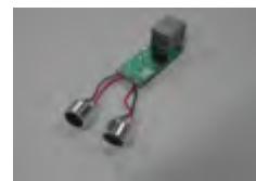
We also are developing a perimeter detection system that will set off warnings at the control console if an unseen obstacle penetrates our Clearance Zone. The Clearance Zone represents the area around the robot that must be clear in order for us to make clean turns and navigate through doorways, paths, etc. We are experimenting with Sharp digital IR sensors and short range LEGO ultrasonic sensors as detection devices.
These same sensors can also be used for autonomous navigation systems.
7. Sensors for Victim Identification
Victim identification incorporates five primary data groups (motion, thermal, CO2, form, sound). We get motion and form direct from the OV7725 color CMOS camera and the SRV-1 camera/control board.
Thermal comes from our custom designed thermal sensor that uses a Perkin Elmer A2TPMI334-L5.5 OAA060 single pixel thermopile sensing element.
CO2 detection is under development. We are making a custom CO2 sensor using a Heimann CO2 Gas Sensor element.
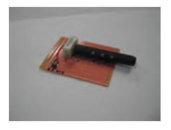
Auditory is also under development. We have used an Audio-Technica ATR35s Lavalier Microphone with some success, but we are pursuing a much smaller device for easier inclusion in our arm head used to insert into smaller access cracks.
8. Robot Locomotion
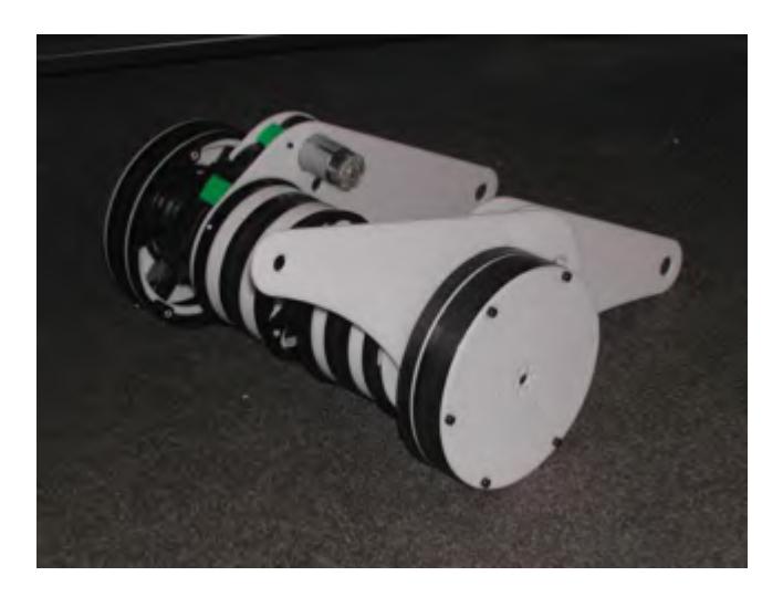
We have taken a new approach to robot mobility. We have moved away from a user controlled climbing arm system and developed a fixed climbing arm base. We feel we can accomplish equal mobility to a managed climbing arm system but with a significant reduction in user complexity. Our new base only requires a basic differential drive control sense meaning the user only needs to know forward, reverse, spin left, spin right, turn left, turn right.
We have retained abdominal belt coverage with our new mobility base. Abdominal belts make almost every bit of the lower surface of the robot a force delivery mechanism, minimizing opportunity to get stuck on a ledge or post that lifts robot wheels/treads off the ground.
Going to fixed climbing arms also significantly reduces the cost of the robot base. With fixed arms there is no longer any need for arm motors, speed controllers, position encoders, etc. Fewer high-torque demands such as comes with climbing arms also means extended operation time of the robot as there are now fewer demands on the battery system.
Another design change is our move away from timing belt driven treads and toward friction driven treads. We've found that employing high incline conveyor belt material as wheel surfaces is more effective in driving the treads. This also allows us to have very loose tread fit. Robots with tight treads or static supports between treads and the driving surface do not make smooth transitions when climbing. Robots of this type must get their center of mass beyond the support location (which transitions from the front of the robot to the center with stiff treads) before the robot will crest on a climb. Once these robots to crest they come down with a decided crash. Essentially, robots with static tread support exhibit a controlled "crash" approach to landings after a climb. With loose treads our new mobility base forms to the shape of the driving surface allowing the robot to fit the climb and make a smooth transition from one surface to the next.
As well as fixed climbing arms we have also gone to only one set of climbing arms. Having removed the second set of climbing arms gets our robot down to a much smaller footprint which should decrease our robot's turning radius making us much more maneuverable.
We have also gone to much lower priced components which helps keep our mobility base cost down, and we hope to have a finished production cost well under $1000 USD.
9. Other Mechanisms
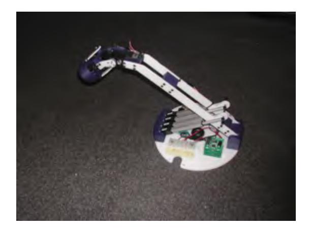
We have a robotic arm manipulated by R/C servo motors and Firgelli linear actuators. The arm head is fitted with a set of the victim ID sensors and a high power LED spot light to illuminate dark areas. The arm allows us to access locations that are beyond the effective range of our mobility base in order to search for victims. We should also be adding a gripping device to the arm to allow for manipulation of environmental obstacles and, potentially exchange items with victims such as bottled water, communication devices and more.
10. Team Training for Operation (Human Factors)
We have constructed a RoboCupRescue test arena in our lab. Students take what time they need on the course to test design concepts and evaluate ease of use and control accuracy of our robots and data systems.
11. Possibility for Practical Application to Real Disaster Site
It seems that many of the developers of rescue and other robot systems (and many of the RoboCupRescue teams) do not design and fabricate their own but instead purchase commercially available robot mobility platforms. Many of these purchased platforms have a price point that makes them impractical for mass market distribution. Our primary goal is to generate a cost effective, highly functional mobility base that gives greater access to rescue robots to all institutions.
We are also targeting ease of use. Many existing mobility platforms are difficult to control without hours of practice. Our hope is for our system to be so intuitive that only minutes of training is needed to accomplish successful operator control.
12. System Costs
System Costs - Operator Station and Components
| Part(s) | Quantity | Total Cost | Internet Site |
|---|---|---|---|
| Operator Station Notebook Computer | 1 | < $1000.00 | Var. |
| Additional Monitor(s) | |||
| External Controls (i.e. mouse, joystick) | |||
| Net Gear Wireless AP | |||
| Communications Lantronix Matchport | 2 | (included in SRV costs) | http://www.lantronix.com/device networking/embedded device servers/matchport.html |
| Mapping ACS IR Scanner | 1 | $375.00 | |
| Sharp GP2D12 IR | (1) | ($12.50) | http://www.acroname.com/robotics/parts/R48-IR12.html |
| Honeywell HMC6343 Digital Compass | (1) | ($149.95) | http://www.sparkfun.com/commerce/product_info.php?products_id=8656 |
| Moog MD6038/6043 Slip Ring Assembly | (1) | ($150.00) | http://www.polysci.com/docs/MD6038_6043.pdf |
| Gear Motor | (1) | ($19.00) | http://www.solarbotics.com/products/gm15/ |
System Costs - Navigation and Victim Identification
| Part(s) | Quantity | Total Cost | Internet Site |
|---|---|---|---|
| Navigation XL-MaxSonar EZMB 1340 Ultrasonic Range Finder | 5 | $150.00 | http://maxbotix.com/uploads/MB1240-MB1340_Datasheet.pdf |
| Victim Identification SRV-1 Blackfin w/OmniVision OV7725 Color CMOS Image Sensor | 1 | $350.00 | http://www.surveyor.com/blackfin/ |
| Audio-Technica ATR35s Lavalier Microphone | 1 | $30.00 | http://www.audiotechnica.com/cms/wired_mics/742fb06dd066b3ec/index.html |
| Heimann CO2 Gas Sensor | 1 | $35.00 | http://www.heimannsensor.com/Datasheet%20HIS%20A21%20F4.26%204PIN_r01.pdf |
| PerkinElmer A2TPMI334-L5.5 OAA060 Single Pixel Thermal Sensor | 1 | $25.00 | http://www.alliedelec.com/Search/ProductDetail.asp?SKU=980-0049&SEARCH=&MPN=A2TPMI334+OAA060+%2F+625&DESC=A2TPMI334+OAA060+%2F+625&R=980%2D0049&sid=47D5CB8035B617F |
System Costs - Robot Locomotion (Mechanical)
| Part(s) | Quantity | Total Cost | Internet Site |
|---|---|---|---|
| Fisher-Price Power Wheels #7 Gearbox w/550 Motor | 2 | $60.00 | |
| AndyMark Plaction wheels am0512 (8 inch) | 3 | $81.00 | http://www.andymark.com/ProductDetails.asp?ProductCode=am%2D0512 |
| AndyMark Plaction wheels am0199 (6 inch) | 2 | $48.00 | http://www.andymark.com/ProductDetails.asp?ProductCode=am%2D0199 |
| AndyMark Plaction wheels am0198 (4 inch) | 2 | $44.00 | http://www.andymark.com/ProductDetails.asp?ProductCode=am%2D0198 |
| AndyMark Omniwheels am-0383 (4 inch) | 2 | $38.00 | http://www.andymark.com/ProductDetails.asp?ProductCode=am%2D0383 |
| Belting | Var. | $100.00 | |
| Fabrication Supplies Axles | $30.00 | ||
| Acetyl Plates | $65.00 | ||
| 3D Printed Parts | $150.00 | ||
| Fasteners | $30.00 | ||
| Misc. Supplies | $50.00 |
System Costs - Robot Locomotion (Control)
| Part(s) | Quantity | Total Cost | Internet Site |
|---|---|---|---|
| SRV-1 Blackfin w/OmniVision OV7725 Color CMOS Image Sensor | 1 | $350.00 | http://www.surveyor.com/blackfin/ |
| Victor 884 Speed Controllers | 2 | $179.98 | http://www.vexrobotics.com/products/vexpro/victor speed-controller.html |
System Costs - Other Mechanisms (Electrical and Arm) and Illuminator
| Part(s) | Quantity | Total Cost | Internet Site |
|---|---|---|---|
| ACS Buss Board | 2 | $35.00 | |
| SLA Battery | 1 | $38.00 | http://www.batteriesplus.com/p-34302-power-sonic 12v-105ah-scooter-battery.aspx |
| Assorted Electrical Connectors/Wiring | Var. | $50.00 | |
| Robotic Arm HSR-5980SG Servo Motors | 3 | $327.00 | http://www.lynxmotion.com/Product.aspx?productID=574&CategoryID=38 |
| Firgelli F-12 Linear Actuators | 2 | $160.00 | http://www.firgelli.com/products.php |
| Gantry Assembly | 1 | $75.00 | http://www.igus.com/wpck/default.aspx?pagenr=3679&C=US&L=en |
| Illuminator Star Bright LED LXHL-LW6C | 1 | $26.99 | http://www.luxeonstar.com/luxeon-v-portable-star led-white-lambertian-120-lm-700ma-p-250.php |
| Fraen Medium Beam Low Profile Lens | 1 | $2.45 | http://www.luxeonstar.com/item.php?id=749&link_str=121::123&partno=FLP-HMB3-LL01-0 |
| ACS Illum. Control | 1 | $20.99 | |
| LuxDrive Buck Puck 700mA Dimmable DC LED Driver 3021DE700 | (1) | ($17.99) | http://www.luxeonstar.com/buckpuck-700ma-dc led-driver-pcb-mount-p-31.php |
| Analog Devices AD5241 Digital Potentiometer | (1) | ($3.00) | http://www.analog.com/en/digital-to-analog-converters/digital-potentiometers/AD5241/products/product.html |
System Costs - Summary Totals
| Category | Total Cost |
|---|---|
| Operator Station | < $1000 |
| Communications | (included in Victim ID and Robot Control) |
| Mapping | $375 |
| Navigation | $150 |
| Victim Identification | $440 |
| Robot Locomotion (Mechanical) | $696 |
| Robot Locomotion (Control) | $530 |
| Other Mechanisms (Electrical) | $123 |
| Other Mechanisms (Arm) | $562 |
| Other Mechanisms (Illuminator) | $50 |
| Combined System Costs | $3,926 |