RoboCupRescue 2011 - Robot League Team STABILIZE (Thailand)
Phanupol Pheungjai, Tawan Buangam, Watcharapong Chaikanta, Sarayooth Changsan, Bandasak Sukpheng, Worawat Chaiwong, Assist Prof. Kamontip Wattakeekamthorn, Thanakit Wattakeekamthorn
Faculty of Engineering Rajamangala University of Technology Phra Nakhon (RMUTP) 1381 Piboonsongkram Rd. Bangsue, Bangkok, 10800, Thailand
Abstract In this paper, the STABILIZE robots from the RMUTP has been briefly discussed. The main purpose of our design is to build two of the teleoperative robots and one autonomous robot. The robots at the RMUTP have been originally designed and developed since year 2008. The presented robots in this paper are also part of our development. Recently, our team has received second runner-up among 12 teams from the National robot competition in Year 2010. The team is prepared for a great challenge in the World Robocup Rescue 2011 in Turkey.
Introduction
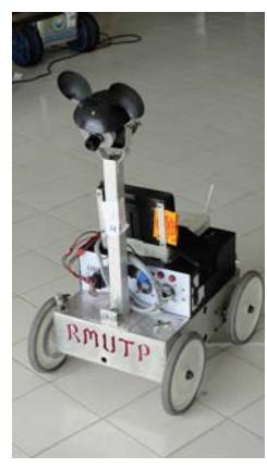
This paper summarized an original concept of the robot configuration from the STABILIZE team. Mainly, there are three robots built from the team. For the first two robots, they were classified as Tele-operative robots in which they are controlled from human manually. For the last, it was known as an Autonomous robot in which it is self-functioning based on pre-command from human.
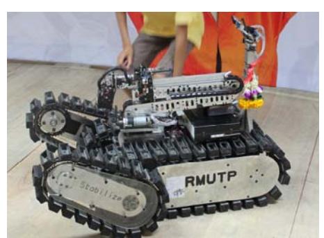
For the tele-operative robots, they are capable of moving on rough terrains, for example, climbing up and coming down from high steep surface conditions. Success behind these robots could be stated from three points. First, it is due to the capability of the dynamic traction control and the use of caterpillar wheels. Second, the additional caterpillar front wheels. Third, the high-torque direct current motor.
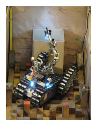
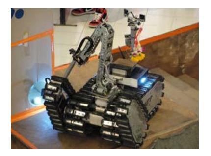
Apart from these advantages, each of the tele-operative robots has one robotic arm installed in the centre. This arm could be extended as long as 1 metre away from its centre. Besides, there are also three cameras installed at the far end of the arm. These are high-resolution cameras and each of them could be controlled from human without interfering the others. Besides, an additional camera has been installed at the back end of the robots. This could be used as the remote eyes for looking around the scene. In terms of climate observation, the team has installed the CO2 sensor and the temperature sensor in the robots for data collection and analysis. Finally, as the robots move along the way, the current position signal would be sent so that the map will be automatically generated.
1. Team Members and Their Contributions
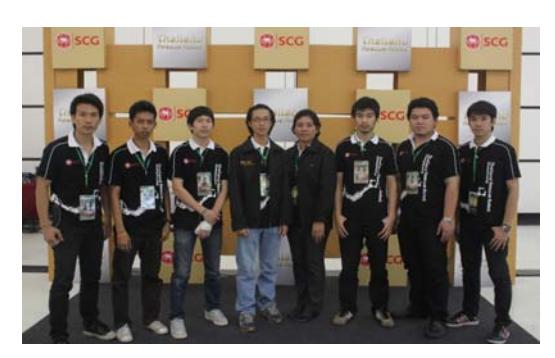
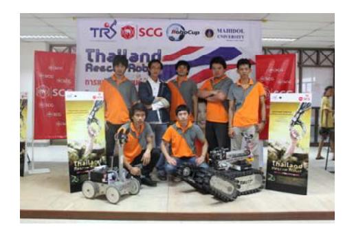
The "Stabilize" Rescue Robot team from the RMUTP, Thailand consists of Engineering students and Academic members within the Faculty of Engineering. Among these members, their contributions stated below:
Team Members and Contributions
| Name | Role |
|---|---|
| Phanupol Pheungjai | Mechanical Arm Design |
| Tawan Buangam | Mechanical Arm Design |
| Watcharapong Chaikanta | Mechanical Drive Design & Robot Control |
| Sarayooth Changsan | Mechanical Drive design |
| Bandasak Sukpheng | Electrical Design & Software Programming (1) |
| Worawat Chaiwong | Electrical Design & Software Programming (2) |
| Assist Prof. Kamontip Wattakeekamthorn | Team co-advisor |
| Thanakit Wattakeekamthorn | Team advisor |
2. Operator Station Set-up and Break-Down (10 minutes)
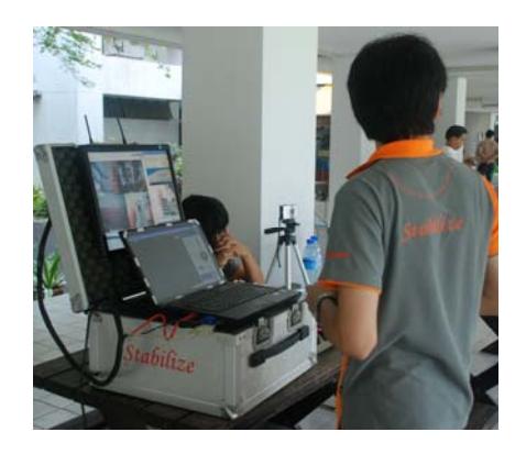
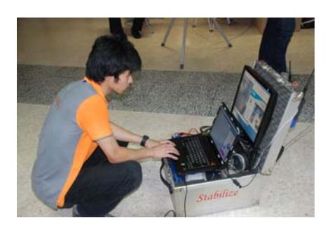
One of the most important considerations in setting up and breaking down the operator station within the time limit is the speed. Hence, our team has designed an aluminum box that can keep all the robot controlling parts in one place. Transporting only an aluminum box is, obviously, much easier than transporting several places of instruments. Furthermore this aluminum box also has a UPS integrated to provide energy backup power, just in case of a power loss. Our team, therefore, is very much confident that our team will be able to setup and break down the operation within the time gone.
3. Communications
The communication between the STABILIZE operator and the robots is operated by using the wireless LAN base on IEEE802.11 a/n standard. This wireless LAN system will help control the robots, receive video streaming from cameras on robots and get sensors feedback for locating the status of robots on computer as well as for the automatic map generation under 5GHz of IEEE802.11 a/n radio frequency. The working distance is in the range of 200m for outdoor, and of 100m for indoor. The channel is adjustable with the power of 200mW.
STABILIZE Communication System Specifications
| Frequency | Channel/Band | Power (mW) |
|---|---|---|
| 5.0 GHz - 802.11a | Adjustable | 200 |
4. Control Method and Human-Robot Interface
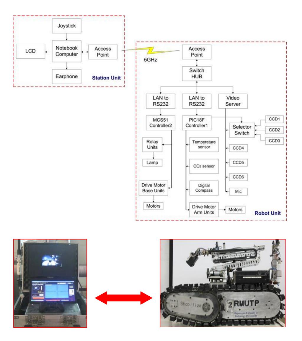
The Graphical User Interfaces (GUIs) used to interface with the robot for the STABILIZE have been installed into 2 separated sites: the robot site (Robot Unit) and the human-machine site (Station Unit). These GUIs could be described along with pictures below:
The frequency for the robot control employs wireless communications of 5 GHz which used for controlling several parts such as: driving mechanics, robotic arm, and also monitoring the CO2 and temperature levels via the user monitor.
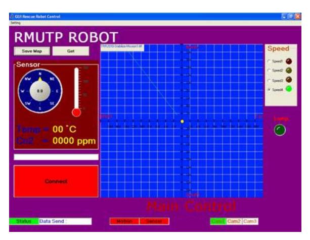
The user monitor displays the CO2 and temperature levels, the current position and the surveying location, the signal conditions, the control buttons, speed control button which as 4 levels of speed control and finally the on-off status of remote robot.
5. Map generation/printing
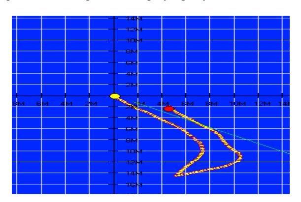
Figure shown below illustrated the location of the robot as it moved along. This is a 2D map where it is capable of displaying any selected victim.
6. Sensors for Navigation and Localization
For our team, there are components detailed below for various sensors:
- 6.1 Laser scan [1]1 set for measuring distance and tell the map size.
- 6.2 Ultrasonic [2] 4 sets for measuring the required distance.
- 6.3 Digital Compass (CMPS-03) [3] 1 sets for finding the point of the compass.
- 6.4 Camera CCD 6 cameras.
- 6.5 XY-plan for measuring robot balance.
7. Sensors for Victim Identification
All of these components would be integrated into one box. This box would be put into the far end of the robotic arm. These components are:
- 7.1 CCD camera for displaying the victim physical conditions.
- 7.2 Temperature sensor [4] for measuring victim's body temperature.
- 7.3 CO2 sensor [5] for measuring climate around the scene.
- 7.4 Emergency light for using in the dark area.
8. Robot Locomotion
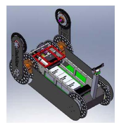
The STABILIZE team has its special design on the robot where it has bigger sized wheels when compared to other robots. This is because the team considered the issue on locomotion of the robot on the rough and steep terrain. The team also designed specific gears for such large wheels. Besides, the team carefully selected the material for the wheels which has its capability on tracking along rough terrain. There are two drive motors for moving forward and backward, including turning left and right. An additional motor is specially designed for driving the front caterpillar wheels which could be 360 degrees turn. For driving the caterpillar wheels, the team used number 40 conveyor belt. The robot has its weight of 60 Kilograms and has its dimension of 54x77x60 cm.
9. Other Mechanisms
The robotic arm can be held as high as 1.8 metres measured from the ground. The designed robots are agile and relatively fast. Although they are light-weighted, they are reasonably strong, durable, and suitable for tough conditions.
10. Team Training for Operation (Human Factors)
Team STABILZED has joined the National robot rescue competition since year 2008. What we have learnt from past makes us stronger and more confident in design rescue robots. We are also proud that we are one of the teams in Thailand that still active and gaining interested not only from students insides but also the Administrative in the RMUTP for funding this robot without hesitation.
11. Possibility for Practical Application to Real Disaster Site
Due to the conflict between the Thai-Cambodian border, our robots are expected to help authorized officers finding any victims during fights against each other.
12. System Cost
STABILIZE team has three robots. Two of which are tele-operative robots and the other one is an autonomous robot. The cost of parts on each robot is listed as follows:
STABILIZE Robot System Cost
| Item | Cost |
|---|---|
| Structure of robot and drive train | $2,900 |
| Hokuyo laser range finder | $2,600 |
| Temperature sensor | $150 |
| CCD cameras x 6 | $320 |
| CO2 sensor | $300 |
| Ultrasonic sensor | $180 |
| CMPS-03 sensor | $133 |
| XY-plan sensor | $70 |
| Controller | $350 |
| Access point IEEE 802.11a | $320 |
| Quad channel video server | $300 |
| Serial server | $200 |
| Total Cost | $7,823 |
13. Lessons Learned
The team, since started working together, has learnt and gained experience not only in engineering designs such as mechanical engineering, electrical engineering, electronic engineering, etc. but also team work which is the most important compared to all required technologies.
References
- www.hokuyo-aut.jp
- SRF05 Ultra Sonic Ranger Technical Specification [Online] Available : http://www.robot-electronics.co.uk/htm/srf05tech.htm [2010, March 11]
- Deveantech Ltd.: CMPS03 Magnetic Compass [Online]. Available: http://www.robotelect ronics.co.uk/shop/Compass_CMPS032004.htm [2010, March 11]
- TPA81 Array Thermopile Technical Specification [Online] Available : http://www.robotstorehk.com/sensors/doc/tpa81tech.pdf [2010, March 11 ]
- K-22 LO sensor Technical Specification [Online] Available : http://www.co2meter.com/products/k-22-lo-co2-sensor-module