RoboCupRescue 2011 - Robot League Team polyMECHanon (Greece)
A. Synodinos, V. C. Moulianitis
Department of Mechanical and Aeronautics Engineering, University of Patras; Department of Product and Systems Design Engineering, University of the Aegean
http://robotics.mech.upatras.gr/ · http://www.syros.aegean.gr/
Abstract This Team Description Paper presents the work done by the Robotics Club students of the University of Patras to sign on the Robocup Rescue 2011 competition. The robot proposed is a tracked platform with a five degree of freedom manipulator and two extra degrees of freedom that connect the main body to the tracks. The robot can function fully autonomous and tele-operated, via remote wireless connection from the operator's station. It can overcome obstacles according to the rules of the competition and carry objects up to 500 grams with its manipulator. It can also function on real disaster sites, aiding in the location of victims and providing support where necessary.
Introduction
The polyMECHanon Robotics Team is a part of the Robotics Group of the Mechanical Engineering and Aeronautics Department (MEAD) of the University of Patras (UoP). Most of the members are undergraduate students of that department with the collaboration of individual students from various departments who share the same interest in robotics. The team operates under the guidance of the Robotics Group, a team consisting of many researchers in the field of robotics led by Professor N. Aspragathos.
The Robotics Group has also previously guided the Robotics Club of the University of Patras; another team of undergraduate students interested in robotics. Through the exchange of experience and ideas, various robotic mechanisms have been built, including a few robotic arms and many autonomous mobile robots. In terms of research, the Robotics Group has taken part in 6 european and 9 national research projects, with Prof. Aspragathos being the coordinating partner in 9 of them.
Team Members and Their Contributions
| Name | Role |
|---|---|
| Nikos Aspragathos | Project Manager |
| Vassilis Moulianitis | Team Coordinator |
| Aris Synodinos | Team Coordinator |
| George Birbilis | Team Coordinator |
| Andreas Mylonakis | Mechanical Design |
| Petros Nikolaou | Mechanical Design |
| Konstantinos Peroulis | Mechanical Design |
| Markos Kapeliotis | Artificial Intelligence |
| Sotiris Xythalis | Artificial Intelligence |
| Nikos Stravopodis | Artificial Intelligence |
| Tzeni Dimoka | Sensors and Sensor Fusion |
| Gerasimos Kounadis | Sensors and Sensor Fusion |
1. Team Members and Their Contributions
[See table above for team members and their contributions]
2. Operator Station Set-up and Break-Down (10 minutes)
The system requires one operator for normal use while two optional users can aid the development and activation of the platform. The full initialization procedure is broken down to these tasks:
- Initial development (3 minutes)
- System activation (2 minutes)
- Communication check (2 minutes)
- Systems check (3 minutes)
3. Communications
We will use the 802.11a (5GHz) wireless communications protocol for all our data transmissions from and to the operator station.
Rescue Robot League Communications
| polyMECHanon (GREECE) | ||
| Frequency | Channel/Band | Power (mW) |
| 5.0 GHz - 802.11a | 100 |
4. Control Method and Human-Robot Interface
The operator of the system has the ability to choose between the use of a wired gamepad and a computer keyboard. The 5 degrees of freedom manipulator is controlled by direct guidance of a 1-1 replica of itself by monitoring each joint of the replica and applying the corresponding control inputs on the robot.
The operator supervises the environment through a GUI which displays the following information:
Table 1. Information displayed on the GUI of the operator
| Sensors | Vision | Robot State |
|---|---|---|
| Temperature | Platform Camera | Batteries Level |
| CO2 | Manipulator Camera | WiFi Level |
| Accelerometers | Kinect Camera | Victim State |
| Gyroscopes | Map | |
| Compasses | Robot Controls |
5. Map generation/printing
For the task of map generation, a 6D-SLAM algorithm developed by the University of Freiburg will be used, supplied by the ROS meta-operating system. The localization is implemented using data from the encoders (dead reckoning) and the IMU (gyroscopes, accelerometers and compasses). The generated map is a point-cloud that builds the 3D model.
The map will have automatically added points of interests, such as victims and their state and special arena features such as stairs, holes etc.
6. Sensors for Navigation and Localization
The platform will be equipped with sensors that provide a complete description of the surroundings while maintaining a low weight and not sacrificing mobility. These criteria led the team to set aside the use of an LRF and instead utilize a MS Kinect 3D Scanner.
6.1 Microsoft Kinect
The Kinect sensor features an RGB camera, a depth sensor consisting of an infrared laser projector combined with a CMOS sensor and four microphones. The frame rate of the output video is set at 30Hz at 640 × 480 pixels with 8 bit resolution. The depth sensing is monochrome in VGA resolution as well, with 11 digits of resolution totalling 2048 levels of depth. The sensor has a range of 1.2 to 3.5m in normal use, although for 3D reconstruction the range is extended to 0.7-6.0m. The angular view is set at 57° horizontally and 43° vertically, with a dc-servo motor built in for tilting (±27°). The audio resolution is at 16 bit with bandwidth limited at 16KHz.
6.2 Inertial Measurement Unit
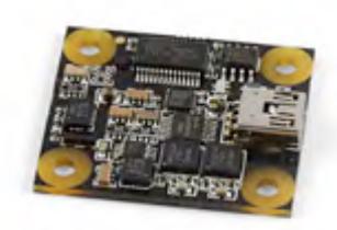
The IMU unit is placed inside the robots main body and provides detailed measurements that characterize the status of the platform and aid the SLAM process. The PhidgetSpatial 3/3/3 has a 3 axis accelerometer with 110Hz sample rate, ranging to ±5G with 300 μG standard deviation at 128 samples/second and 230 μG" resolution. The gyroscope ranges ±400 °/s with 0.02 °/s resolution and 4° typical drift / minute. The magnetic compass has a minimum resolution of 400μG with 2° typical offset from North. The communication interface is through USB at 250 samples/sec with 45mA current draw over the 5V USB cord.
6.3 Encoders
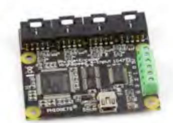
The velocity of the tracks will be monitored by encoders at all times for both the control of the driving motors as well as for the utilization of the SLAM algorithm. The PhidgetEncoder Highspeed 4-Input is able to read four encoders simultaneously at 250000 counts/second max speed at 1μs resolution with 125 samples/second communication speed via USB. The power requirements are at maximum 500 mA when all the channels are enabled, while the device itself consumes 30mA of that current over the 5V USB connection.
7. Sensors for Victim Identification
For the victim identification and characterization, various sensors have been utilized with the use of sensor fusion techniques based on computational intelligence.
7.1 Temperature Sensor
The sensor used to detect temperature changes in the environment is the popular TPA81. This sensor is a thermopile array that can measure simultaneously 8 points up to 2 m away in a field of view of 41° by 6. Each thermocouple detects the infrared emissions in the 2-22μm range, which is the range of the radiant heat. The TPA81 is mounted on the end effector of the manipulator
7.2 CO2 Sensor
For the detection of the CO2 concentration, the MG811 sensor has been used. This sensor can measure concentrations ranging from 350 to 10000 ppm and is the fastest of its kind, with response times up to 10 sec and warm up time of 30 sec. This makes it by far the fastest CO2 sensor available for this kind of use. It's only disadvantage is the high power consumption, which can be overlooked if a tight power management approach is utilized. The sensor is mounted on the end effector of the manipulator.
7.3 Sound
A directional microphone has been utilized to isolate the acoustic signal from the background noise. Audio filters have also been used to remove noise from the locomotion of the robot and the external sound sources. The microphone is mounted on the end effector of the manipulator.
7.4 Vision
The platform is equipped with two extra cameras, besides the one located on the Kinect 3D scanner. The first camera is mounted on the end effector of the manipulator, while the second one is tilt and pan controlled and located on the rear of the platform, supervising the workspace. The algorithms implemented are able to detect motion and do face recognition. With the fusion of the readings of all the sensors, the distance of the located objects can be calculated.
8. Robot Locomotion
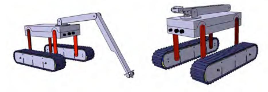
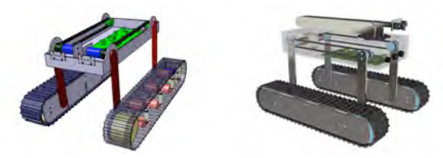
Our system's mobility is based on tracks. Two independent tracks are supporting the main body by four links. The links are actively articulated by two, and are mechanically coupled. So both links of the right or left side can be independently controlled, and therefore the distance between the tracks and the body can be altered. This approach offers great mobility without the sacrifice of passive unclarity or controllability. Overall, the system operator has only four degrees of freedom to control, which makes the tele-operation simple and robust. On rough obstacles, stairs or other hard obstructions, the platform can perform full rotations of the links around the body, and therefore move on a stepping pattern.
The tracks are powered by two dc brushless motors while the links are powered by high torque stepper motors. Each link is mechanically coupled with its corresponding pair by a timing belt.
The platform is equipped with an R-P-P-PR 5 degree of freedom manipulator powered by DC servo motors. The arm is equipped with a gripper capable of grasping and carrying objects of small size weighting up to 500 grams.
9. Other Mechanisms
[See subsections below]
9.1 Integrated Controller
The PhidgetSBC2 is a Single Board Computer with an ARM CPU at 400MHz, 64MB RAM and 512 NAND memory for storage running a Debian Linux Distro. The platform is equipped with 6 USB ports, an Ethernet port and 8 analog inputs, 8 digital inputs and 8 digital outputs. This platform will be used to control the DC motors (PID control with the use of the encoders), to collect the data from all the non-vision based sensors and conditioning them as well as to control the stepper and servo motors of the robot and manipulator respectively.
9.2 Computer System
For all hard computing tasks, an onboard computer will be utilized, responsible with the tasks of SLAM, Vision, motion planning and high level sensor fusion.
9.3 Batteries
The system will be powered by Li-Ion cells, located partially inside the tracks and partially inside the main body, in order to balance the weight. The dc motors will be powered exclusively by the batteries inside the tracks, while the sensors and all the other motors will be powered by the batteries of the main body.
9.4 Motor Drivers
DC Motor Drivers: To drive the dc brushless motors used to power the tracks, a Phidget 1064 - PhidgetMotorControl HC has been utilized. This driver allows allows the control of the angular velocity and acceleration of up to two high-current DC motors. The control loop is refreshed at 50Hz with a resolution of up to 1.5%. It can deliver up to 14A of continuous power, or 32A of peak power for a short period. It connects directly through an isolated USB cable. Overvoltage, overtemperature and overcurrent conditions are fed back to the API on the PC.
Stepper Motor Drivers: For the stepper motors used to articulate the links, a pair of Phidget 1063 - PhidgetStepper Bipolar is used to control the position as well as velocity and acceleration of the links with high holding torque and precision. It has a very high resolution and can deliver up to 75W per coil. Typical jitter can be 10- 30msec, so precise synchronization cannot be made, but in our implementation that is neither crucial nor expected.
Servo Motor Drivers: The Phidget 1061 - PhidgetAdvancedServo 8-Motor can control up to 8 servo motors with power ratings of 24W per motor and 180W in total. It has a resolution of 125 steps per degree and allows the monitoring of the current draw of each motor individually which can help debugging in case there is a malfunction and assure the fault tolerance on a real disaster site.
9.5 Communication Architecture
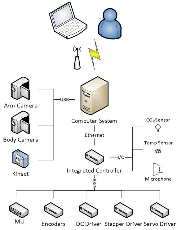
The communication between the computer system and the cameras is made through USB protocol, while the integrated controller communicates with the computer through Ethernet TCP/IP via the PhidgetWebService. The integrated controller connects to all the phidgets directly through USB and to all secondary sensors through digital I/O pins.
10. Team Training for Operation (Human Factors)
The operator must be trained in order to properly deploy the system on the disaster site. The teleoperation by itself is straight forward, through a GUI and the system is guided with the help of a gamepad and a manipulator 1:1 replica. Former experience on the system would definitely be beneficial, though not required.
Our team operator will be trained in order to be as efficient as possible in terms of time scheduling and energy minimization in our destruction arena as well as on real life conditions in testing unknown scenes.
11. Possibility for Practical Application to Real Disaster Site
The system has been designed with the objective of rescuing in a real disaster site. It is easily carried and deployed within a few minutes by trained operators. It can be guided by any trained or untrained operator, with, of course, obvious advantage of the first. The system's mobility allows it to access almost any terrain, while at the same time being able to overcome obstacles that a traditional tracked robot wouldn't be able.
Our platform will be tested extensively on an arena built according to Robocup's specifications and afterwards will be tested on real terrain with the goal of eventually being integrated as a part of the Hellenic Rescue Team (E.M.A.K.).
12. System Cost
[See table below]
Table 2. Cost of the platform with the manipulator
| Part Name | Website | Cost |
|---|---|---|
| Mobile platform | Custom Made | 3000€ |
| Motors (DC, Stepper, Servo) | 1000€ | |
| Sensors | http://www.phidgets.com/ | 1200€ |
| Cameras | 300€ | |
| Kinect | 150€ | |
| Computer | http://www.mini-itx.de/ | 800€ |
| Batteries | http://www.all-battery.com/ | 300€ |
| Manipulator | Custom Made | 1000€ |
| Total | 7750€ |
13. Lessons Learned
[No content provided in the paper for this section]