IranOpen 2013 - Robot League Team ASEMA-MASHIN (IRAN)
Elham Iravani, Arash Khajehpour, Mojtaba Mahdipour, Ali Shirazi, Shermin Motameni
Islamic Azad University of Tehran North Branch; Islamic Azad University of Damavand
Abstract This paper describes our approach for the Iran Open 2013 Real Rescue League. This robot has a control preparation according to the multi layer architecture researched and designed by our team members. We have both autonomous and manual rescue robots. The fully autonomous rescue robot consists of two completely separated parts. The Mobility system which is designed with low center of gravity to control the robot in the massive realistic situations, and the Artificial Intelligence Mechanisms system (AIM) to identify the victims using some common sensors which are practiced and enhanced in the laboratories by experiments designed. The manual rescue robot is able to move around the orange and red area by telecommunication. We had approached the mapping problem of autonomous robot by a new Windows and Linux operating system based algorithm. The members of this team achieved some good grades separately in the Real Rescue League in previous competitions: The first place of 4th Khwarizmi competition and 3rd international Robotic competition of Amirkabir University, 2012. The first place of best in manipulation of 16th International Robocup competition Mexico, 2012. The first place of best in manipulation of 7th International Robocup IranOpen competition, 2012.
Introduction
Our Robot name is that mean an ancient Persian word meaning Great Master.
The "ASEMA-MASHIN Team" is a team consists of two graduated students of Computer Engineering from the Islamic Azad University of Tehran North Branch, And three B.S students of Electronic Engineering from the Islamic Azad University of Damavand, Tehran, Iran.
Our robot's task similar to others rescue robots is finding victim and reporting the situation and position of them. We have two important parts: One of them is hardware and another is software. Hardware included mechanic and electronic, and Software included the program for moving, detection, Localization and network communication.
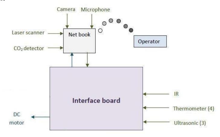
The Artificial Intelligence Mechanisms (AIM) system, in the autonomous robot, contains a netbook which runs a main processing program designed and enhanced for directing the robot in the maze and finding the victims. The AIM system also contains an interface circuit as a middle part electronic board designed to connect to the sensors and getting data by a serial port and bring them to the netbook.
The whole procedure is to receive data from sensors and process them into information used for the localization algorithms and victim identification. The mapping algorithm is ran on the netbook on the robot and the 2D map of the areas is generated in it based input data. This mapping algorithm uses some geometrical and statistical approaches. We observe information that appeared in netbook on the robot by remote desktop software at operator station system.
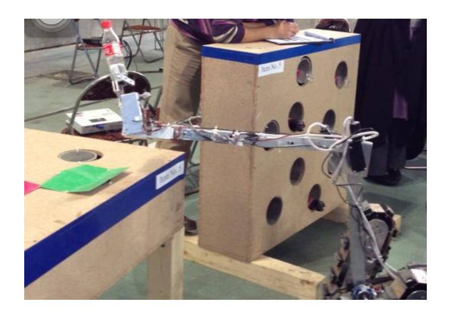
Drivers of the manual robot are designed by ours. We also design a good control panel for controlling robot. We have also one flexible arm on the robot for moving the battles, drugs and O2 capsules for victims in manipulation.

0- Hardware and software components
This robot similar to other robots includes two parts:
- Hardware
- Software
We explain both of them briefly:
a. Autonomous Robot
1. Hardware: Platform
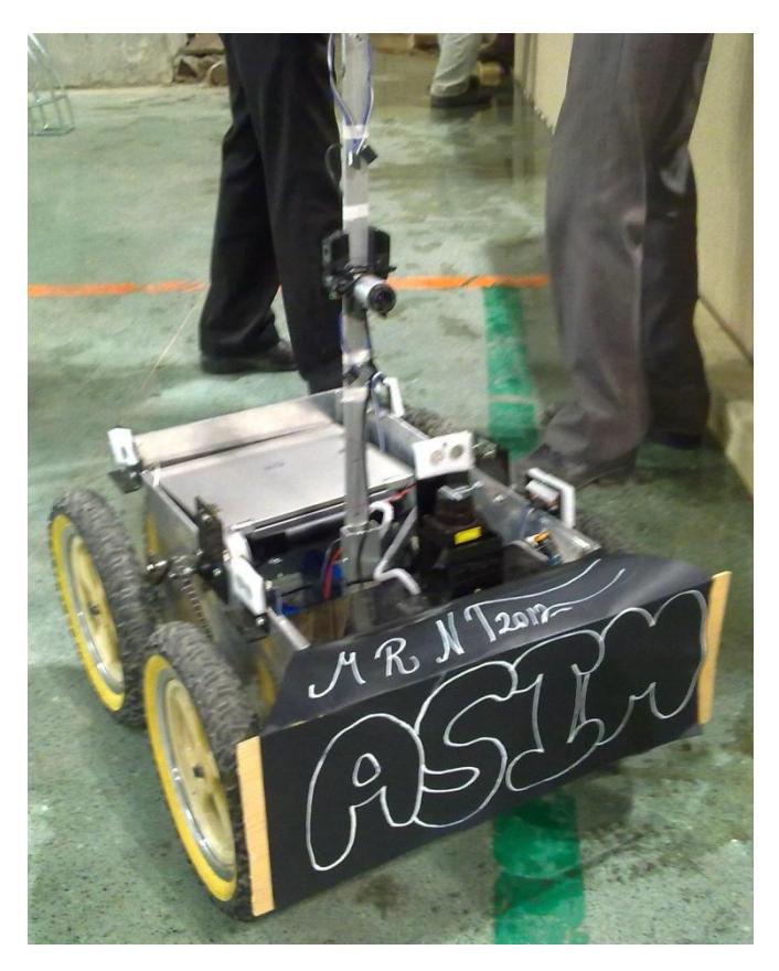
Based on four wheels and two motors
Wheel: Diameter: 30 cm, Thickness: 5cm, Bicycle wheels
Motor: 60RPM (ZGA42FM ZHENGK 12V) http://landaelectronic.com/
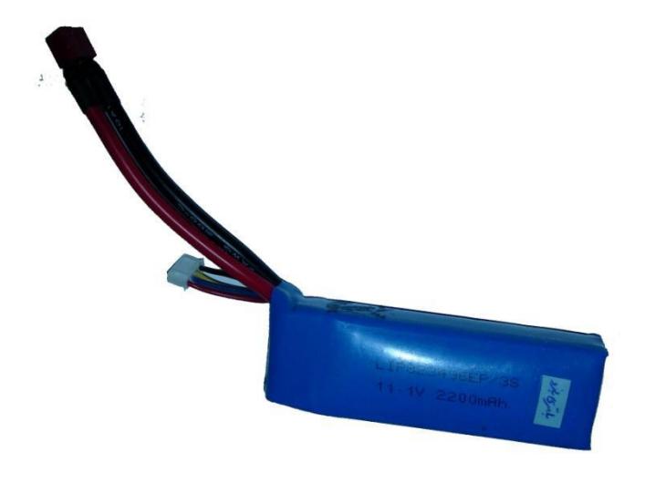
Battery: 11.4 Volt DC, 5 Ampere, 11.1 Volt DC 0.85 Ampere (LIT-POLY) www.gitabattery.com/
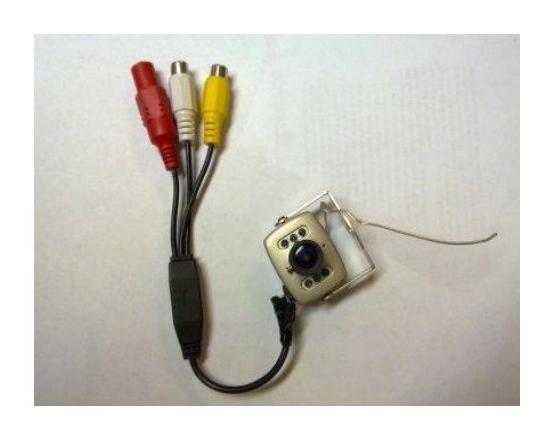
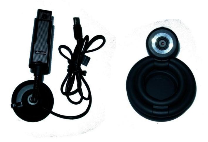
Camera: We receive webcam data alive on remote desktop from two USB cameras http://chinatronic.com/products.php/JMK-WS-309AS/cPath,8
Electronic staff: We design an interface board for Sensors data receiving and the other on is used for voltage dividing, and also driver (12V input, 80A)
Sensors:
IR sensor
- Detection distance: 10cm to 80cm http://robot-electronics.co.uk/datasheets/gp2d12_e.pdf
Thermometer (TPA81)
- Temperature range: 4°C ± 100 °C
- Communication: I2C interface
- http://robot-electronics.co.uk/htm/tpa81tech.htm
Ultrasonic (SRF02 and SRF08)
- Range: 16cm ± 6m
- Communication: I2C interface
- http://robot-electronics.co.uk/htm/srf02tech.htm http://www.robot-electronics.co.uk/htm/srf08tech.html
Compass
- Resolution: 0.1degree
- Communication: I2C interface
- http://robot-electronics.co.uk/htm/cmps3tech.htm
Co2
- Measurement range: 1000ppm ± 5000ppm
- Communication: I/O communication
- http://www.parallax.com/StoreSearchResults/tabid/768/ProductID/886/Default.aspx
Accelerate meter
Gyro
Router
- U WRT 320N-EE (IEEE 802.11n, g, b, 802.3, u, ab ± Dual band, Selectable band 2.4 or 5GHz)
- http://downloads.linksysbycisco.com/downloads/datasheet/WRT320N_V10_DS_Rev_B_web.pdf
- U Gaming Router WL-309 (Wireless simulation dual band) http://www.sitecom.com/gaming-router/
- U USB Wireless (DWA-160) http://www.dlink.com/products/?pid=DWA-160
Laser Rang Finder
- Hokuyo URG-04LX (Detects up to 4m distance, in 240° each 0.36°) http://www.hokuyo-aut.jp/02sensor/07scanner/urg_04lx_ug01.html
Microphone TieClip Microphone
b. Manual Robot
Platform: Based on war machine structure
Motor: BMW Motor, Motor 55RPM, http://landaelectronic.com/
Battery: 12.0 Volt, 10 Ampere, 11.1 Volt DC 0.85 Ampere (LIT-POLY) www.gitabattery.com/
Camera: We receive webcam data alive on network from four cameras http://chinatronic.com/products.php/JMK-WS-309AS/cPath,8 Digital Video Recorder four channels
Electronic staff:
- We design an interface board for Sensors data receiving and the other on is used for voltage dividing, and also driver (12V input, 80A)
- Control panel for moving robot and arm
Sensors:
Thermometer (TPA81)
- Temperature range: 4°C ± 100 °C
- Communication: I2C interface http://robot-electronics.co.uk/htm/tpa81tech.htm
Co2
- Measurement range: 1000ppm ± 5000ppm
- Communication: RS232 communication
- http://edinst.com/pdf/Gascard%20NG%20Datasheet%20Rev1.pdf
Router
- U WRT 320N-EE (IEEE 802.11n, g, b, 802.3, u, ab ± Dual band, Selectable band 2.4 or 5GHz)
- http://downloads.linksysbycisco.com/downloads/datasheet/WRT320N_V10_DS_Rev_B_web.pdf
- U Gaming Router WL-309 (Wireless simulation dual band) http://www.sitecom.com/gaming-router/
- Wireless Access point WA-11500 TP-Link http://www.tp-link.com/en/
- U USB Wireless (DWA-160) http://www.dlink.com/products/?pid=DWA-160
Microphone
- Tie-Clip Microphone
2. Software
a. Autonomous Robot
Movement Robot: It sets motor to go forward, backward, turn Right, turn Left by data from Sensors.
Victim detection: It finds victim with thermometer, Co2 detector and voice data.
Step field detection: It finds steps with IR & Ultrasonic sensors.
Data Capturing: It captures data from laser scanner.
Localization & Mapping: It helps robot to find obstacles and generate a 2D map.
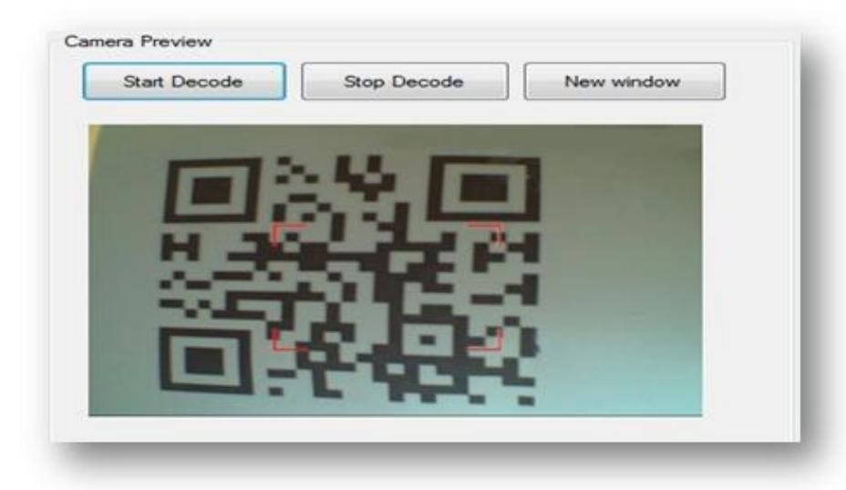
Decoding QR code: It helps robot to decode QR codes
Remote Desktop & Network: It uses software for accessing netbook screen on the Robot and send/receive data from Robot.
Light Manager: It uses for watching the frames that is captured by cameras.
b. Manual Robot
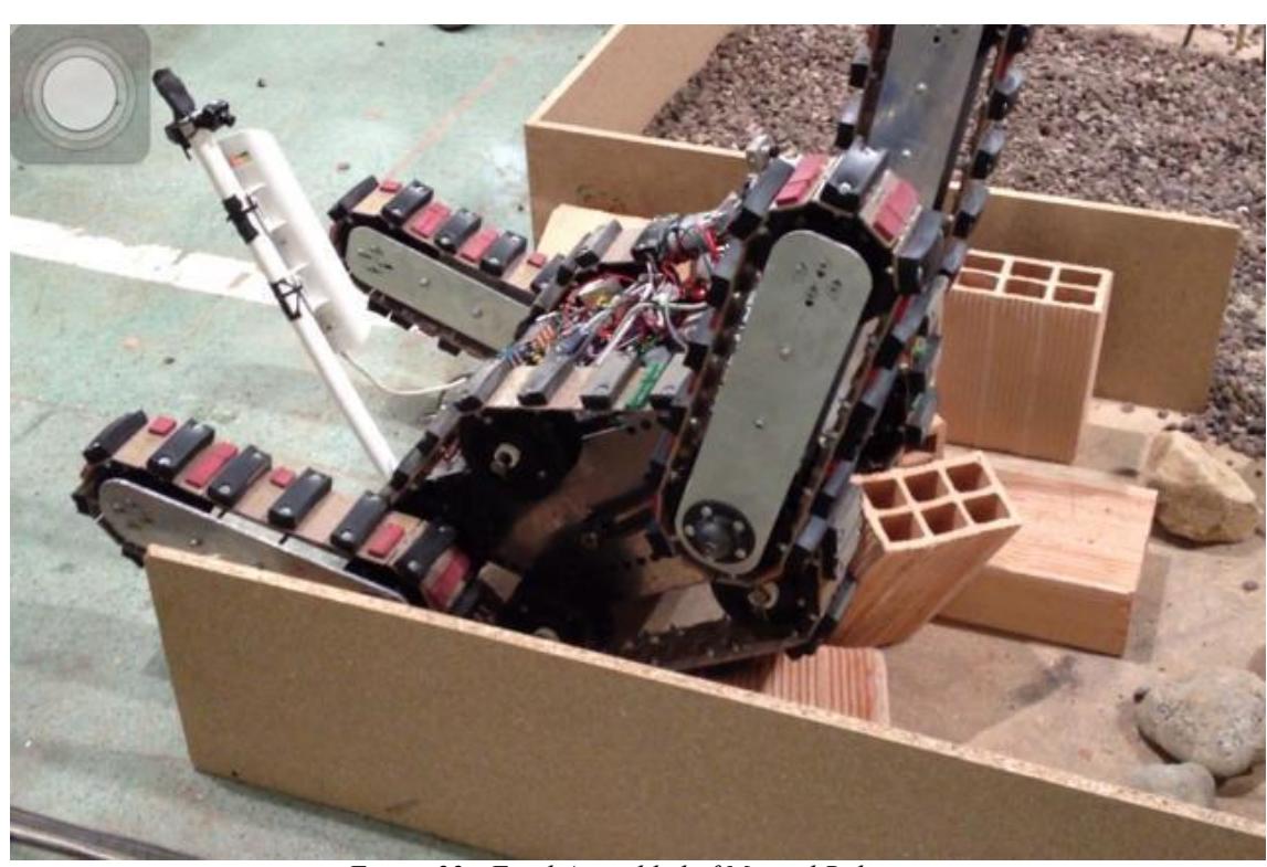
Movement Robot: It set the motors to go forward, backward, turn Right, turn Left, move four separated flippers and arm by receiving commands from operator system through the drivers. The operator controls the robot by Control Panel or a GUI with some keys on a keyboard.
Victim detection: It actives after the operator saw the victim and sent it a command. It presents vital signs. The operator can search victims with moving the arm according to the captured video and sound.
Wireless Network and Radio Frequency: It sends camera data via a DVR to operator system screen by a 5GHz wireless baud rate. Control panel uses Radio Frequency waves to connect robot for controlling it.
1. Team Members and Their Contributions
Elham Iravani Head of Programming, Supervisor of 2D Mapping algorithms Developer & Programmer, AIM System Programmer, Operator-Side GUI Developer & Programmer, Navigation Algorithms Developer & Programmer, Voice Detection Algorithms Developer & Programmer, Sensors Processing Algorithms Developer & Programmer, Data of Laser Range Finder Capturing Algorithms Developer & Programmer.
Mojtaba Mahdipour Head of Mechanical System Designers, Mobility System Designer Supervisor.
Arash Khajehpour Head of Electronic System Designers, Electronic System Designer, Wireless Infrastructure Network Administrator, Operator.
Ali Shirazi Manipulation Designer, Electronic Assistance, Mechanical Assistance.
Shermin Motameni Team Leader AIM System Programmer, Operator-Side GUI Programmer, Voice Detection Algorithms Developer & Programmer, Sensors Processing Algorithms Developer & Programmer, Data of Laser Range Finder Capturing Algorithms Developer & Programmer, Wireless Infrastructure Network Administrator.
2. Operator Station Set-up and Break-Down (10 minutes)
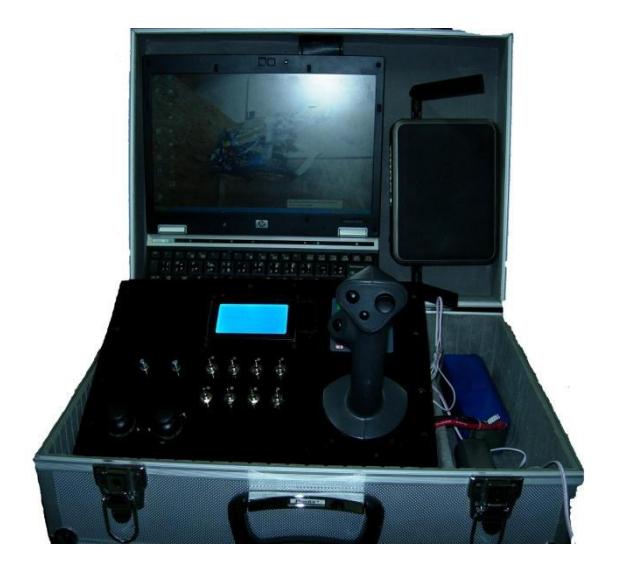
There is a laptop in the operator-side control station, a wireless router, gaming wireless simulation for enhance wireless waves and writing tools.
Within the 10-minute-time limit, we boot up the operator station and wireless communication modules and check for the functionality of the victims' life alarms. We have a Graphic User Interface software on operator's which visualizes the sensors data input and the live video transmission directly from the robot's AIM system.
We need two people to carry the package and each person has to setup the parts he carries. One person will connect the laptop accessories such as wireless router and printer and the other person will prepare the writing tools and make sure the sensors work.
Since the robot is fully autonomous, we estimate that the setup procedure will take less than 7 minutes and the break down takes similar time.
3. Communications
As it is suggested, we connect via remote desktop on the netbook of the robot for receiving data alive. It causes to reduce network traffic.
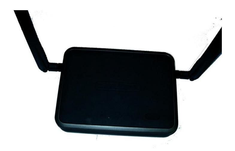
We are also use a wireless LAN connection with a Standard IEEE 802.11A ± 5GHz. in case we lose the remote desktop connection, so we can switch to it and gain control over the robot in critical situations.
As a replace, we use a remote switch which powers out the robot and shuts the AIM down to avoid the robot from going out of control.
Also we use wireless simulation gaming router for to strengthen network.
| Rescue Robot League | |||||
|---|---|---|---|---|---|
| ASEMA-MASHIN (IRAN) | |||||
| Frequency | Channel / Band | Power (mW) | |||
| 5.0 GHz - 802.11A | 8 | 350 | |||
| Short Distance Remote Switch | 2 | Low |
4. Control Method and Human-Robot Interface
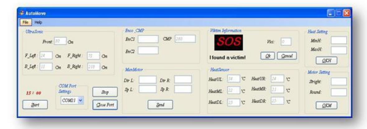
Please Since our robot is an autonomous robot, it does not need direct commands from the operator and the Artificial Intelligence Mechanisms system (AIM) works itself by gaining data from the environment and processing them and alerting the operator when finding victims. So the operator-side Graphic User Interface does not include any mobility controlling command options but just the visualizers of the sensor's data input which are processed by the AIM system from the robot.
The GUI is a Visual C# .Net Windows application which runs on the operator's laptop. It contains the different parts for sensors. The operator can see all the sensors measurements.
We have designed the robot so it can have the connection to the operator station every moment and uses the bandwidth in an enhanced way. The sensors over the robot get and send raw data to the AIM system and the system processes them into a reliable form and sends them to the station in every intervals and whenever a suspicious condition is detected.
The AIM system sends the sensors' measurements to the operator's laptop in a cycle every second. The cycle loops to the beginning and the sensors start sending information again. So it does not drive traffics to the network bandwidth and we can use the bandwidth for much more commands.
The suspicious situations are motion detection, heat and CO2 gas increase in the environment, and human voice. Working with microphones faced us a few problems in the laboratories experiments because of low accuracy. Infrared CO2 Gas Analyzer is a reliable sensor so we can be sure the robot has found a victim whenever its visualized list up. The Infrared Thermometers send temperature of the environment with good resolution and can help the robot in victim identification. The surrounding Ultrasonic rangers help the robot find the path and do not let the robot get very close to the obstacles. They are also taking responsibilities of 2D map generating and giving the operator a better sense of environment.
We have also implemented an Infrared range finder on front of the robot to check for any step fields or obstacles near the robot so it can be informed and change direction to avoid colliding with them. In order to avoid the robot colliding with obstacles or victims, there has been implemented a few algorithms which causes the robot better mobility and navigation.
The map generation is fully autonomous and the operator does not need to mark the victim's place in the map. All needed is to wait for submitting the information of the victim and sending a continue command to the robot when it has found a victim. During the missions there will be no need for human operations unless some system fails.
5. Map generation/printing
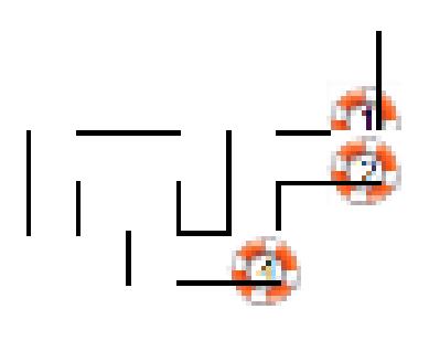
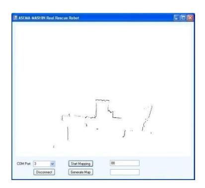
The map is generally created by the AIM system and fully automatic, based on the path robot has traveled by scans of the Laser Range Finder and ultrasonic rangers and also the commands to the motor drivers and the speed of the robot. The map file will be created in robot's netbook in real-time process of the data received. The output will be ready immediately after the mission is over. According to the new rules, the operator can't correct the map by hand. The map contains the position of the victims and the obstacles for victim searches and all other marking notes which must be placed. [2]
We have presented a soft approach for building a 2D map of the earthquake environment using an autonomous rescue robot. It uses some basic geometrical and statistics approaches to gain a suitable map. The map is generated step by step by using most of the particles. After that it optimized the particles to determine real positions of obstacles.
We also use an Accelerate meter to control the situation more carefully. The resulted map is processed by using some mathematical algorithms. The sent beams by the LRF may face three situations. 1- Show the obstacles, 2- Show the environment, 3- Do not get back (such as glassy surfaces or inexistence of obstacles).
The robot creates the map by a new algorithm that is designed and developed with new method. This map generation is based on localization and robot movement on pallets and the data of the laser range finder. It can filter extra data by some geometric concepts. It uses some Boolean variables and motors variables to determine direction and navigate well. It gets help the speed of motors to masseur distance that robot traversed.
In the end it is important to mention that the generated map has to get updated in a cycle with importing new data from the environment and continue the generation the map process. [4]
In the future we will propose a new localization algorithm using this map. It can do vision like a human.
6. Sensors for Navigation and Localization
We implemented an algorithm for localization using some useful sensors. It should detect the obstacles and find the suitable path as fast as possible.
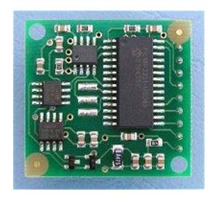
6-1 - Electronic Compass
The electronic compass is a great tool used for directing the robot to the points desired and also has an important role in creating the 2D map of the area. The SLAM algorithms use the values given by the digital compass with a resolution of 0.01 degree and marks the different parts of the map in the way desired.
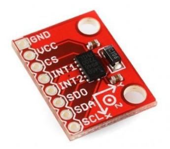
6.2 - Accelerate meter
This sensor makes output as differences of linear acceleration via direction. It can compute the acceleration from 2g up to 16g. We could calculate angel differences of some important sensors like laser range finder, by this sensor.
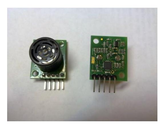
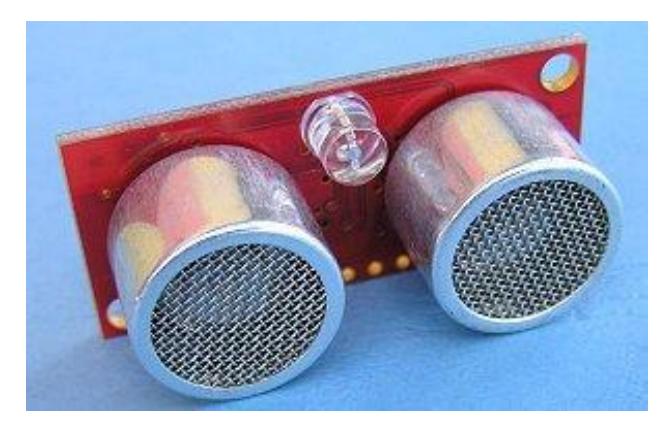
6.3 - Ultrasonic Rangers
We have implemented three ultrasonic rangers on the robot. Two of them are on the both sides of the robot and one in front of it. There are two ways for ranging:
- 1 Time Of Flight Measurement (TOF)
- 2 Measurement of Phase Difference
In the first way, the ultrasonic module sends a wave and calculates the time of travelling of the wave before receiving it again. The second way is to measure the difference between phases of more than one signal from the module. However it is accurate, it has a limitation to an only one frequency of about 40 KHz and less than 8 mm of difference. The most common way of ranging in robotic is the TOF way but it has a major problem that is Crosstalk. Crosstalk is from something else for example another ultrasonic module or waves from other elements of the circuit. We can remove crosstalk by using some pseudo random sequences.
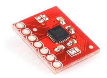
6.4 - Gyro Sensor
6.5 - Laser
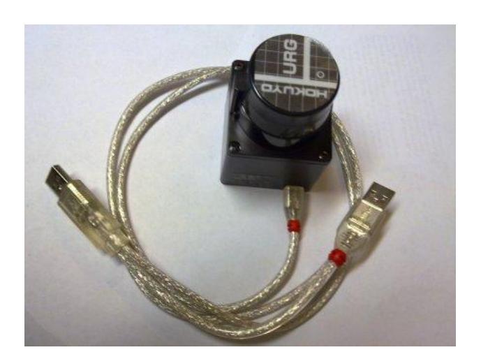
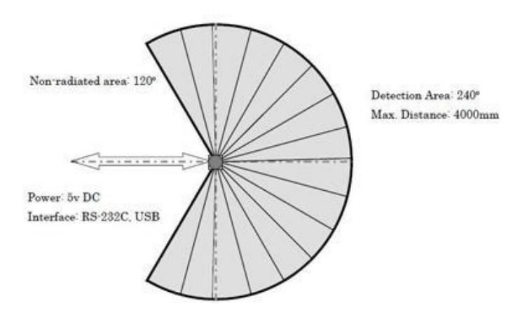
We use a Hokuyo URG-04LX-UG01 laser range finder which has a 240-degree scan and a 4 m distance coverage which is one of the best range finders for the robots so far. The resolution of the scanner is 0.36 degree and is good enough for the robot to gain a full control over the maze and the obstacles. It gives about 683 values of distances each scan and every 100 ms and fills an array of distances and creates a matrix which can be processed into a 2D map.
6.6 - Odometer
We had implemented an odometer system on the wheels and were receiving data from them but the laboratory experiments did not have exact and reliable results and the data had a low accuracy. Especially when using newspapers on the grounds and forcing wheels to turn without moving the robot. So we decided not to use the odometer system. Instead we designed a distance-meter using a time counter and the speed of the wheels so we could estimate the distance traveled by the robot from a point to another. The laser range finder also has the major role in correcting the map with high accuracy.
6.7 - Camera
It was first supposed to plug the USB camera to the AIM system on the robot and use some Image Processing Algorithms to find victims and obstacles but the plan changed due to the limitation of time. The operator can watch its movie alive. The digital cameras are used for find the QRCODE in the field.
7. Sensors for Victim Identification
This is an introductory paragraph for victim identification sensors.
7-1 - Infra Red Thermal Sensors
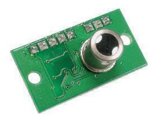
Our main Victim Detector Sensors are IR Thermometers which are designed in the center of the AIM system and are used to detect the temperature differential between parts of the environment. Each temperature between 32 and 40 degrees is marked as a victim suspicious situation and alerts the operator and waits for his command to whether check for victims or not. Other victim identification sensors activate after the checking command to the robot.
7-2 - CO2 Gas Analyzer
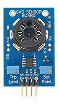
The Carbon Dioxide (CO2) Gas Analyzer is a very reliable and accurate sensor which we use. We can be sure about a victim when the light on the board turns on. Also the sensor shows the amount of the gas in ppm. The amount of CO2 produced by human during breathing is above 2000 ppm and that is the base number we use to check for the presence of a victim.
7-3 - Victim Voice Detectors (Microphones)
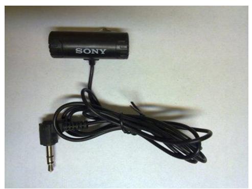
The AIM system is equipped with 2 microphones in the sensors' package in front of the robot and can receive any voices in a distance so the victim's voice is cached and sent directly to the operator's station and the operator can hear the voices in the area and check for victims. We are also working on an algorithm which can process the microphone input into a value in db using the Fast Fourier Transfer. It might be available until the competition.
7-4 - Motion Detector
The GUI system on the robot is using a software designed an enhanced by the EASYCAP company to have a great control on the images received by the camera. These results enable the operator to check the images for any motion and alerts in the moment. The sensitivity of this feature can be tuned to the best which helps the operator to recognize any victim motion even if he is not looking at the images.
8. Robot Locomotion
This section describes the robot's locomotion systems.
8-1 - Wheels (on autonomous robot)
We are using 4 simple wheels with 30 cm diameter and enough stability on the rolls and pitches of field. They connect two by two with chains and gears to the Motors.
8-2 - Motors
The robot uses 2DC geared motors with the output near 60 RPM which is enough and suitable for our robot. This provides the robot with a speed desired as calculated below:
60 RPM != 60 Rounds per Minute != 6 Round per 1 Seconds Circumference of the Wheels != π * 30 != 94.2 cm
94.2cm per 1Second. This rate is too much for an autonomous robot so it reduces velocity to get better performance.
8-3 - Power Supply
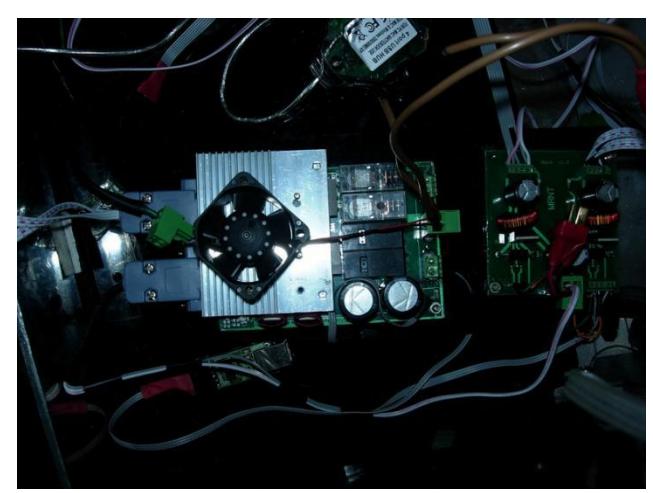
The robot uses one 11.4 Volt DC lithium polymer battery with a power of 5 A. This current is enough for the interface electronic circuits, Motors Driver and Motors. The robots have another lithium polymer battery (11.1 Volt DC with 0.85A) for the cameras.
9. Other Mechanisms
This section covers additional mechanical and design aspects of the robot.
9-1 - Image Processing
We use the camera that has the ability to turn on the infrared lights in the dark positions and uses the night mode with a good coverage of about 30 cm from the lens. This image processing can help us to detection the tag of the victim.
Tricks are commonly used for light sensing and equipping the camera with a night mode, which helps the users to have a feeling from the environment without the need of light projectors and torches.
9-2 - Completely Departed Design
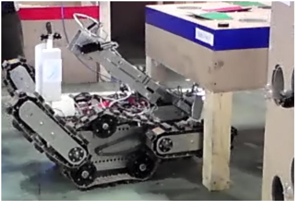
The mechanical design based on four wheels. Electronic boards and battery fixed in aluminum base (They are in a separated box in manual base.). Netbook is fixed on top of the aluminum base and the camera and thermometers are stick on a fixed arm. In the autonomous robot, there is a battalion place for moving each thermometer and camera around that it will be active when find a victim (It is under construction.). The laser range finder is on the balancer on the platform. The other thermometer and ultrasonic sensors were fixed around the platform.
In the manual robot, thermometers and cameras are on a flexible arm. (Figure 17)
9-3 - Interface Circuit
For the full autonomy it is necessary to use a microcontroller or a microcomputer with an embedded processor.
There are two ways for communication between I/O devices and net book:
- We can use a hub series;
- We can use an interface unit;
We preferred to use an interface unit for detecting our devices because a hub series have a time-out and more processing burden. Time-out will make interrupt.
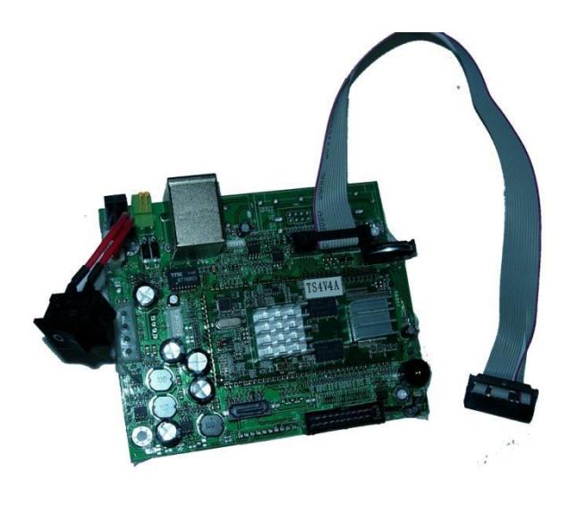
The interface board of this robot has designed by our team and it is based on some PIC microcontrollers. One of the microcontrollers connects to netbook with I2C to USB connector for transferring data. [6]
The interface board makes processing of netbook easier because it guides the netbook that what input device sends the information for it. It is a modular controlling system for monitoring the sensor data, for controlling the actuators and tasks for planning and navigation of the robot. It is used in order to receive information from sensors and devices that gathers the existence environmental information on the robot and transfer the information to the netbook.
The I/O devices connectors enter the analog information by connecting on the frame of interface board. [7][8][9][10]
10. Team Training for Operation (Human Factors)
Since the robot is fully autonomous, the required team training is to know how to turn on the robot and the different parts of the electronics systems and how to run the application on the robot's netbook. They GUI application on the laptop in the operator's station is a user friendly API and does not need any kind of practical factors to mention.
11. Possibility for Practical Application to Real Disaster Site
We were in eight competitions since 2010 and gained lots of good experiences, but our main goal is to design a real rescue robot to use for finding victims and checking damages of buildings during real earthquakes which are so common in our country, and try to improve our robot for each competition.
12. System Cost
Here are costs of the parts used for the robot. All prices are in the US Dollar.
Autonomous Robot:
| Module | Description | Price per piece | Cost |
|---|---|---|---|
| Power Source | Battery 11.4 VDC - 5A | 1 | |
| 11.1 VDC ± 10A | 400.00 | 587.42 | |
| 11.1 VDC ± 0.85 A | |||
| Wheel | Four wheels (30 cm diameter) | ||
| Motor | Two DC Motor | 56.6 | |
| Ultrasonic Ranger | Five SRF02 | 30. | 169.8 |
| Laser Range Finder | URG-04LX-UG01 | 1280.55 | 1280.55 |
| Camera | Two Webcam | 34.13 | 68.26 |
| Net Book | Hp Elitebook 2530p | ||
| Microphone | Two | 5.00 | 10.00 |
| IR Thermometer | Six IR Thermometer (TPA81) | 113.45 | 680.70 |
| DC Motor Driver | MDV02 | 150.00 | 150.00 |
| Electronic Compass | One (CMP S03) | 54.21 | 54.21 |
| Remote Switch | One | 11.10 | 11.10 |
| Gaming Router | Sitecom wl-309 | ||
| IR Range Finder | One (GP2D12) | 22.33 | 22.33 |
| Mechanical staff | Aluminum and Plexiglas parts | ~.00 | .00 |
| Electronic staff | Interface Circuit | ~ 200.00 | 200.00 |
| Total | 5127.28 $ |
Manual Robot
| Module | Description | Price per piece | Cost |
|---|---|---|---|
| Power Source | Battery 11.1 VDC ± 10A | 400.00 | |
| 11.1 VDC ± 5A | 1 | ||
| 11.1 VDC ± 0.85 A | |||
| Wheel& Gears | Six wheels | 40.00 | 420.00 |
| Six Meter gears | 30.00 | ||
| Motor | Two BMW Motors | 300.00 | 1150.00 |
| Two DC Motors | 100.00 | ||
| Seven small DC Motors | 50.00 | ||
| Camera | Four Camera (JMK) | 34.13 | 368.96 |
| Two Webcam | 36.12 | ||
| DVR | 160.20 | ||
| Net Book | Msi 370 | 307.00 | 307.00 |
| IR Thermometer | Four IR Thermometer (TPA81) | 113.45 | 453.80 |
| Microphone | Two | 5.00 | 10.00 |
| DC Motor Driver | MDV02 | 150.00 | 350.00 |
| MDV04 | 200.00 | ||
| Remote Switch | One | 11.10 | 11.10 |
| Mechanical staff | Aluminum and Plexiglas parts | ~200.00 | 200.00 |
| Electronic staff | Interface Circuit | ~ 400.00 | 400.00 |
| Total | 5558.28 $ |
13. Learned
In the first time we made the robot with two wheels but in last competitions it could not move in the inclined plan land well, so we changed the mechanic to be faster and to be able move better. Also the Network had high traffic while it transferred information on wireless broadcast so we try to use Remote Desktop for being WLAN better.
Two last competitions helped us to make the robot better and we make new manual robot with the special mechanic design. We hope that it will move so well in the future.
Also now we could generate new algorithm for mapping. The result can also improve our localization.
References
- J. Suthakorn*, S.S.H. Shah , S. Jantarajit , W. Onprasert and W. Saensupo, S. Saeung, S. Nakdhamabhorn, V. Sa-Ing, and S. Reaungamornrat "On the Design and Development of A Rough Terrain Robot for Rescue Missions". Proceedings of the 2008 IEEE International Conference on Robotics and Biomimetics Bangkok, Thailand, February 21 26, 2009
- Stefano Carpin, Holger Kenn, Andreas Birk. "Autonomous Mapping in the Real Robots Rescue League".
- Bruno Steux, Oussama El Hamzaoui Mines ParisTech. "CoreSLAM : a SLAM Algorithm in less than 200 lines of C code".
- Chiara Fulgenzi a, Gianluca Ippoliti b, SauroLonghi b,* "Experimental validation of Fast SLAM algorithm integrated with a linear features based map".
- J. Z. Sasiadek, A. Monjazeb ," A Comparison between EKF-SLAM and Fast-SLAM", Department of Mechanical and Aerospace Engineering, Carleton University 1125 Colonel By Drive Ottawa, On, Canada, K1S 5B6
- Smith, Microelectronic circuits, 2003
- Mazidi Mohammad Ali, Mazidi Janis Gillespie, Interface circuits, 2004
- Ugatah Hiku, Control engineering, 2004
- P.Nelson Victor, Negal H.Troy, Cerroll Billd, Irwin J.David, Digital logic circuit analysis and design, 2002
- K.Lala Parag, Digital system design using programmable logic devices, MA: Addison-Wesley, 1990
- (Asim2012, Iran) AUTCUP2012 TDP, 2012