RoboCupRescue 2013 - Robot League Team Cuerbot (México)
Jose J. Lopez, Gerardo M. Mendez, Jose Valderrama, Zazil Nasta, Alejandro Hernandez, Daniel Soto, Armando Fuantos, Alejandro Garrido, Carlos Mondragon, Adrian Canseco
Instituto Tecnologico de Nuevo Leon, Av. Eloy Cavazos 2001, Tolteca Guadalupe, N.L. MX 67170; Universidad de Montemorelos, Av. Libertad 1300 Pte, Montemorelos, N.L. MX 67530
http://robotica.itnl.edu.mx · http://www.um.edu.mx
Abstract This project is developed based into six wheels no holonomic with gravity center fixed mobile robot for rescue operations in Mexico, our principal goal is type-2 fuzzy logic algorithm to evaluate victim state and position; in this project use a software embedded to apply our control algorithms and manage data acquisition and actuator enveloped. Robotic design includes an innovative technique to evaluate route measurement with dual sensor style.
Introduction
For this project we are working in a real situation of support for rescue teams of Nuevo Leon State, our topography is special for tracking vehicles and for this reason work with this type locomotion system. Taking as reference RoboCup rules [1], we consider CO₂, body temperature, sound and video processing; additional variables to consider are proximity detection and level position. To link all these variables we use I²C network under serial connections, every node in this network have either two elements: microcontroller and level conversion circuit. This microcontroller has a simple responsibility, manage a Universal Algorithm to Read/Write our Environment (UARWE), this algorithm includes protocol algorithm. All this nodes are controlled by an embedded card that uses C++ as platform to develop mapping and robot control. Some previous works was presented by [2,4,5,6]
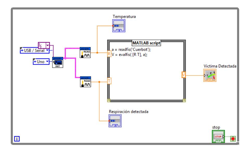
For control algorithm we use two programs: one based in fuzzy logic type II with two options to evaluate, both are developed in embedded card with MATLAB and LabView software, this program consider CO₂, body temperature (IR sensor), displacement and voice as inputs to evaluate, as output victim detection and, second Finite State Machine FSM algorithm is developed for single robot's displacement. It's very important take a consideration always manual control of robot movement is present and control algorithm helps to give a guide to operator to drive this robot.
For a communication we use two links to make contact with operator and robot, WiFi type N net is used for PC-PC communication, with regular configuration defined for parameters of TCP/IP protocol. In this case one computer (master) controls robot and another computer is a slave of the other, using software to remote control. The frequency managed is 2.4 GHz, and all characteristics enveloped in WiFi Consortium.
For video management we use one fix camera. Fix camera uses WiFi link this camera generate a high quality image to process with control algorithm, located on embedded platform system.
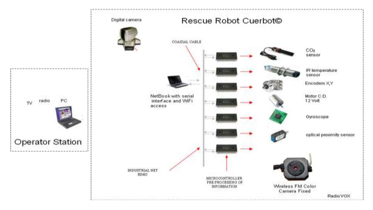
Additional hand radios are used to communicate with victim, one in vox mode located inside of robot and other in Operator Station as half duplex mode, this radios are using amateur frequency 146 MHz in FM mode. To give exact position of robot we consider two sensors to evaluate this date, gyroscope MEMS sensors that evaluate three axis position and acceleration and two encoders to make a measure of two axis positions, both variables are connected to microcontrollers commented lines up. Around robot structure we fit six proximity sensors to detect wall and free space, all processing is realized in control algorithm.
As mechanical references we use three mass elements to move this robot, one is main structure where caterpillar and mechanisms are linked to produce X, Y movement, another two structures are helping to climb and move down the main structure, every structure has a similar bonds with tracking system, maintaining or trying to, fit always our center of gravity.
For all this work we made some research over projects presented in lasted RoboCup competitions and as reference our participation local robotics contest; we try to evaluate our preliminary results and obviously our actual participation will be reflected in a potential product to introduce to national market free of providers of rescue robots.



1. Team Members and Their Contributions
Daniel Soto Electronic systems design
Zazil Nasta Electronic y Mechanics systems design
Carlos Mondragon Software system design
Adrian Canseco Telemetry design and data acquisition system
Armando Fuantos Mechanical design and actuator design
Alejandro Garrido Auxiliar Robot Implementation Gerardo M. Mendez Control design
Jose Valderrama Energy sustainable systems
Jesus Lopez-Villalobos Robot design and control software programing
2 Operator Station Set-up and Break-Down (10 minutes)
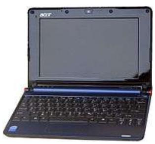
The operator system is packed in one middle Cuerbot suitcase, and the robot is also packed in one large size Cuerbot traveling box.. Suitcase weight will not exceed 10 kg. and our robot is previously fully ensembles, to large travel it can be dismounting an re ensemble again. Our Operator Station is formed either Computer (netbook) or smartphone, dedicated as interface of embedded card located in robot, all programs are located there; another accessory is one video and receiver of fix camera and the last element is a hand radio to receive environment sound from robot. All are fixed ergonomically with suit case. A regular power supply is added to manage 110 VCA, but it is prepared for emergency energy plant or 12Vcd batteries. The setup is quickly is just plug and play and for break down in similar way.
3 Communications
The method of communication between the user and the robot will be by means of one laptop that have control over other embedded computer managed remotely, communicated a network Wi-Fi type N. Internal communication will be handled directly with I²C network that will connect to microcontrollers with net bus [15], who will be in charge to receive and to carry out the orders that the mother-board requires Another links are used for FM video transmitter with 2.4 GHz frequency; for voice link uses a regular hand radios in the VHF amateur band (144-148 MHz).
Table 1. Frequencies table used for this robot.
| Rescue Robot League | |||
|---|---|---|---|
| Cuerbot (MEXICO) | |||
| MODIFY TABLE TO NOTE ALL FREQUENCIES THAT APPLY TO YOUR TEAM | |||
| Frequency | Channel/Band | Power (mW) | |
| 2.4 GHz - 802.11n | 3 | 500 | |
| 2.4 GHz - Other | FM | 500 | |
| 147 MHz | 147.5 MHz | 1000 |
4 Control Method and Human-Robot Interface
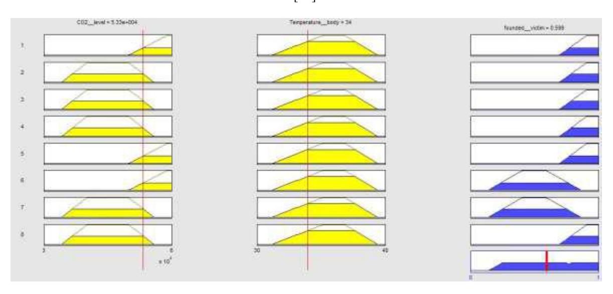
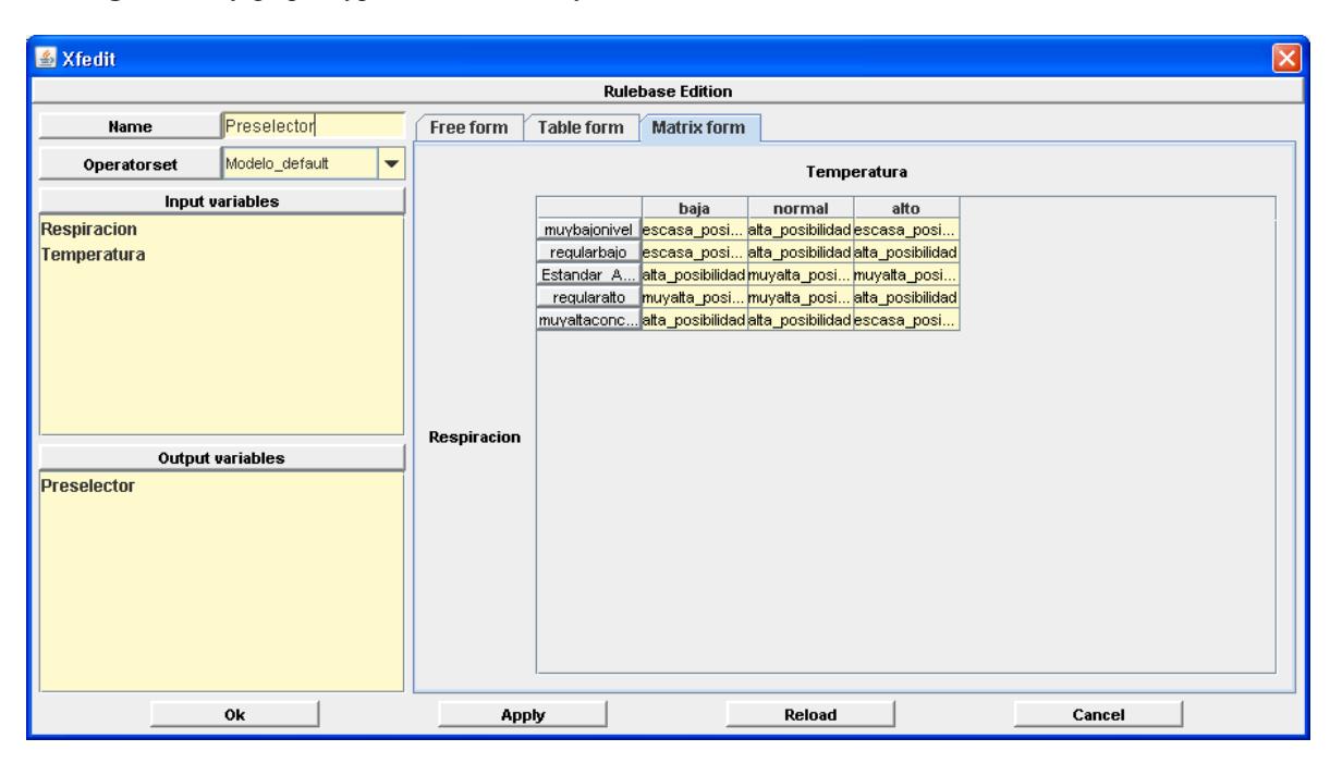
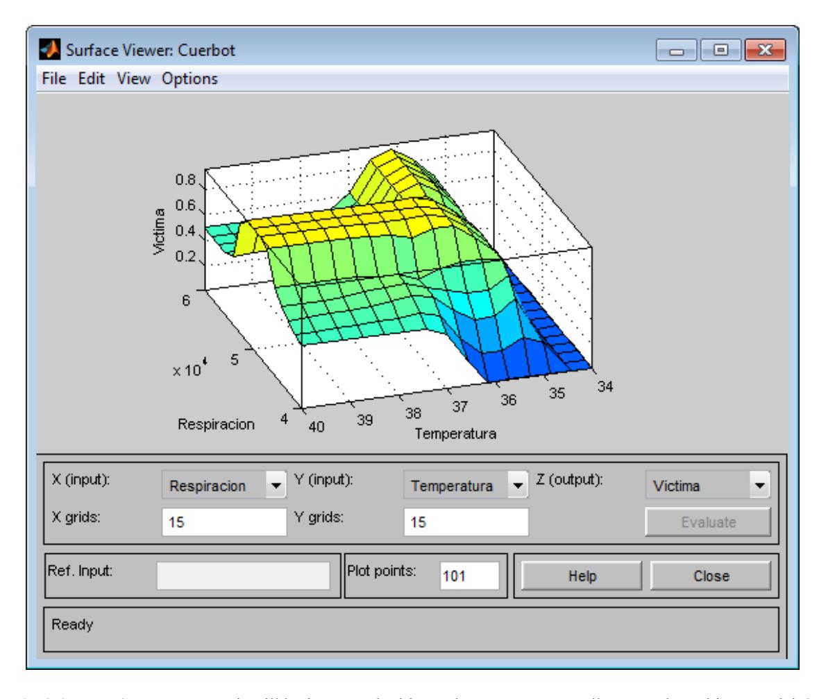
In the control method, already detected the variables of the victim by means of the sensors they are analyzed by means of fuzzy logic type I methodology. For the process of fuzzyfication the operators used are Min-Max method, this give us an implication of variables becomes taking minimum from the exit variables, they are added considering its maximum values of each one of the same exits of the activated rules, and the method of desfuzzification is the centroid in the diffuse algorithm obtained a total of 9 evaluated rules and at the moment it is continued valuing the exact specification of the model for the detection of victims; as reference, comparing with old model reduce 30 % of computational process. For future hardware mapping decision, consider two steps for fuzzy control, first victim's found subsystem and second voice analyze subsystem; for linguistic description variables Gaussian shapes are preferred, but in some cases trapezoidal graphs are used too. Some preliminary results, give us some differences about victim age; and it's expressed by different desfuzzification phase outputs with similar form but variable highly dependent of age. The last results give opportunity to use type-II fuzzy logic as methodology to found better refined desfuzzification victim variable [8]. All environments are developed in LabView 8 to take access to interfaces and be compatible with OS. This part is been currently developed, but this manages motion control and victim detection indication in robot teach box, we are trying to connect a mechanical displacement accessory (joystick), using info packet over TCP/IP. Some references were in [3,6].
Type-2 fuzzy logic systems
Interval type-2 (IT2) fuzzy logic systems (FLS) constitute an emerging technology. A type-2 fuzzy set [1], denoted by $\widetilde{A}$, is characterized by a type-2 membership function $\mu_{\widetilde{A}}(x,u)$, where $x\in X$ and $u\in J_x\subseteq [0,1]$: and all variables enveloped into human detection are evaluated under this consideration.
$$\widetilde{A} = {(x, u), \mu_{\widetilde{A}}(x, u)} | \forall x \in X, \forall u \in J_x \subseteq [0, 1]}$$
and $0 \le \mu_{\widetilde{A}}(x,u) \le 1$. This means that at specific value of x, say x', there is no longer a single value as for the type-1 membership function (u') [8]; instead, the type-2 membership function takes on a set of values named the primary membership of x', $u \in J_x \subseteq [0,1]$.
It is possible to assign an amplitude distribution to all of those points. This amplitude is named a secondary grade of general type-2 fuzzy set. When the values of secondary grade are the same and equal to 1, there is the case of an interval type-2 membership function. In human detection, the inputs of the IT2 FLS model are the victim's body temperature, CO2 composition, and the voice frequency.
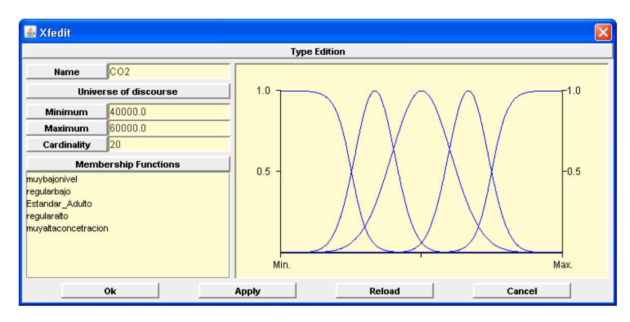
The architecture of the IT2 FLS is established in that way those parameters are continuously optimized. The number of rule-antecedents are fixed to three; one for the body temperature (divided into three IT2 fuzzy sets), one for the CO2 consumptions (divided into five IT2 fuzzy sets), and one for the voice frequency (divided into five IT2 fuzzy sets), resulting (3 * 5 * 5 = 75) twenty five rules. Gaussian primary membership functions of uncertain means are chosen for the antecedents and consequents.
The resulting interval type-2 TSK FLS uses type-1 singleton fuzzification, join under maximum t-conorm, meet under product t-norm and product implication.
The training mechanims used is the back-propagation (BP) method.
The IT2 CTC model has three four inputs $x_1 \in X_1$, $x_2 \in X_2$, and $x_3 \in X_3$ and one output $y \in Y$, and a rule base of size M = 75 of the form:
$$\widetilde{R}^I:\text{IF}$$ $x_1$ is $\widetilde{A}_1^I$ and $x_2$ is $\widetilde{A}_2^I,$ and $x_3$ is $\widetilde{A}_3^I,$ , THEN $y$ is $\widetilde{G}^I$
where l=1, 2, ... 75. These rules represent a fuzzy relations between the input space $X_1 \times X_2 \times X_3$ and the output space Y, and are complete, consistent and continuous.
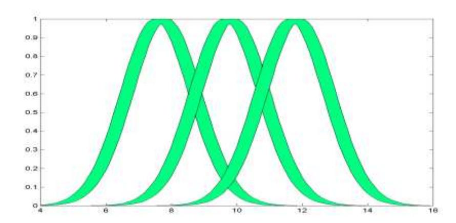
The primary membership function $\widetilde{A}_1^l$, $\widetilde{A}_2^l$ and $\widetilde{A}3^l$ of each consequent is a gaussian function with uncertain means, see Fig. 1. Since the center-of-sets type-reducer replaces each consequent set $C{\widetilde{G}_l}$ by its centroid then $v^l$ and $v^l$ are the consequent parameters
centroid, then $y_l^l$ and $y_r^l$ are the consequent parameters. Initially, only the input-output data training pairs $(x^{(l)}:y^{(l)})$, $(x^{(2)}:y^{(2)})$, ..., $(x^{(N)}:y^{(N)})$ are available and the initial values for the centroid parameters $y_l^l$ and $y_r^l$ may be determined according to the linguistic rules from human experts, as is the case of this application.
![Fig 4.2 Structure of I/O of fuzzy controller, for this case Pre-selector controller evaluate human variables available CO₂ and temperature; fitting controller evaluate audio voice, this step is changing with old age. This first evaluation steps was developed in fuzzy type I style, as reference as start point to variable evaluations [22].](/tdps/rescue_robot__2013__Cuerbot/_page_4_Picture_0.jpeg)
![Fig 4.8 FSM algorithm tested by SimForge tool for manual control of robot displacement, this figure depicts Petri Net equivalent for general structure [23,24].](/tdps/rescue_robot__2013__Cuerbot/_page_7_Picture_1.jpeg)
Additional notes on control algorithms
For basic movement of robot an Finite State Machine FSM algorithm is currently designed for manual control, the simple way to represent this control is following joystick over user indicated displacement, i.e., moving left indicates to motor their current flow and as speed regulation based into two PWM duty cycles previously fixed ( k= 0.45 and 0.8). As experience, an improved technique over speed motor control is developing to prevent recurrent damage over DC drivers.
Both control algorithms are initially implemented in embedded card that but some deficiencies are detected in past, to improve it, some powerful computer are better; for this reason an atom processor changes all software potential . In this version an netbook are used with graphic language with quick access to every sensor and actuator [12,13]. This computer is supported with auxiliary Arduino microcontrollers.
5 Map generation/ printing
For mapping generation we are designing a program to detect obstacles and give telemetry info about position of robot and victim detection. We are integrating in embedded card a control protocol program that obtains info of encoders, gyroscope and accelerometers, all of them are processed for this program. An develop XÝ map tool is currently developed to show and print robot position, in this moment only simple detection of trajectory is created, for victim detection fuzzy algorithm helps to main program to establish the possibility of victim presence. For measurement proposes, we are using metric units. This program is making developed in LabView.
6 Sensors for navigation and localization
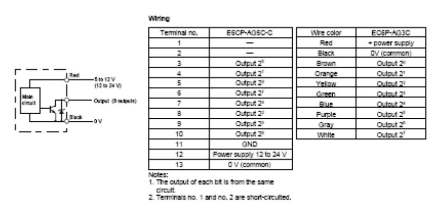
For this purpose we use old sensor scheme used in previous prototype, remembering it consider two element to make it, two absolute encoders located into robot structure an they give us 360° for X-Y Axis motion, their mechanical mounting will be specified in the next sections. In this case electrical parameters are compatible with TTL level managed by microcontrollers used in this robot, all information is driving with control PC program into embedded card. The resolution of this sensor is 4 revolutions by one track band revolution considering 0.000694 lineal meters reflected in X- Axis and for Y-Axis consider angular displacement 1440 pulses by revolution.
Another innovator element included is a gyroscope based in MEMS technology to give us either two parameters: level and acceleration measurement, digital output in serial format is used to communicate with your corresponding microcontroller. This smart sensor has a resolution of 0.004° by axis and considers 3D level detection and, in similar manner is treated acceleration measurement.
Both displacement sensors used are evaluated to prevent false measurement by wheels sliding and home fixing, additional algorithms are developed to translate acceleration and binary to ASCII conversion.
![fig 6.2: iSensor based in MEMS 3D level and acceleration [14].](/tdps/rescue_robot__2013__Cuerbot/_page_8_Figure_6.jpeg)
Additional sensor information
As proximity wall and space detection we use four optical sensors symmetrically hosted in robot structure to give to control program information about tracking and obstacles detected for these sensors, they are directly coupled to microcontroller because they have fixed distance detection and obviously uses discrete signals.
7 Sensors for Victim Identification
Essentially four victim detection is evaluated to use as references to detect initial human conditions, all of them are directly connect to embedded control system; mixed output signals are used to connect to embedded controller. Our sensors for human identification are:
The types of sensors to use are:
- CO2 sensorial gas: It contributes to the perception and identification of the gas emitted by man, is not necessary its calibration, can detect from 0 to 100,000 ppm; it is necessary to be located closer to robot without human physical contact, around 20 cms;
- Absolute encoders: Located one in each gear of the flank of the robot, it will show to the number of returns or revolutions to us that each gives to the band that crosses a certain position, their values will not lost your exact position. On the other hand, internal counter is implemented to register all complete rotations of every encoder.
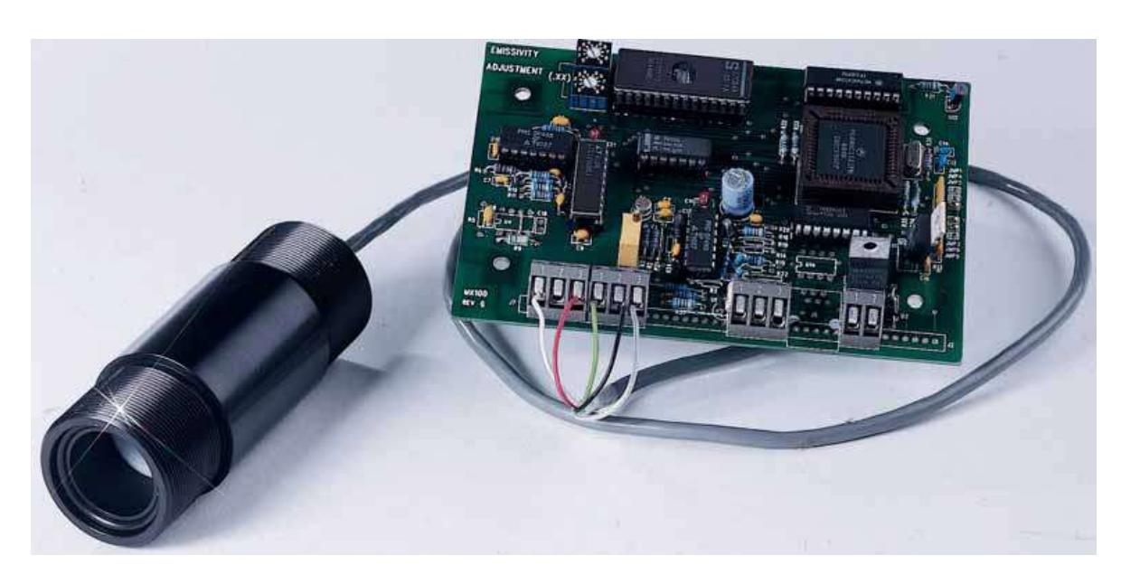
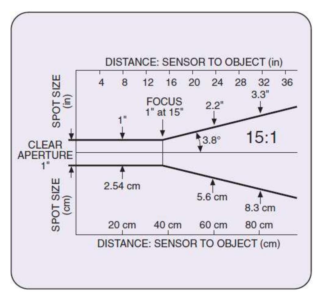
- IR thermal: This sensor is essential to make measurements of health conditions over body; our typical range over 34 to 40 degrees is covered over this sensor of 0 to 50 degrees centigrade, with acceptable resolution. Additional DAQ circuit was designed to connect with embedded system, as default voltage output is 0 to 5volts, easy to convert to digital form.
Table 3. CO₂ sensor characteristic table
| Characteristic | Range |
|---|---|
| Output signal range: | Standard level |
| Input potential: | 0-4 volts |
| Gas sampling mode: | 5 volts ( + 0.25 V) |
| Normal operating temperature range: | 25ºC (+ 5ºC) |
| Operating humidity range: | 5-95% (non-condensing) |
| Storage temperature range: | -40 to 65ºC |
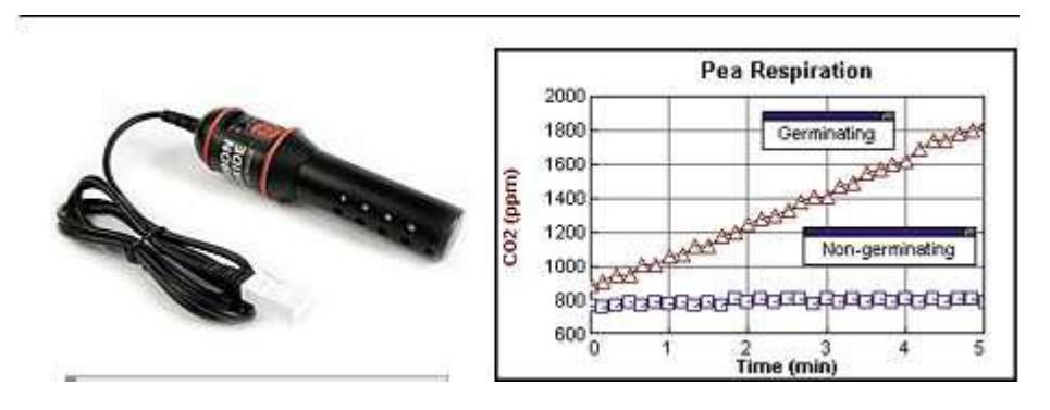
Table 4. IR temperature specifications
| Characteristic | Range | |
|---|---|---|
| Sensing range | 0300 | |
| Type | OD 100 GA 300 | |
| Voltage Supply | 18…32 DC | |
| Current consumption | <40 mA | |
| Current output | 4…20 mA | |
| Angle of vision | <10º | |
| Reproduction | +1 ºC | |
| Temperature coeficient | +0.1 of the measuring value | |
| Response time | <100 ms | |
| Measuring accuracy | +3 of the measuring value | |
| Ambient temperature | -10…+60 ºC | |
| Load resistente RL | <500 Ω | |
| EMV-class | A | |
| Protection [EN 60529] | IP 67 | |
| Material | AISI 316 Ti | |
| Connection | M12 connector |
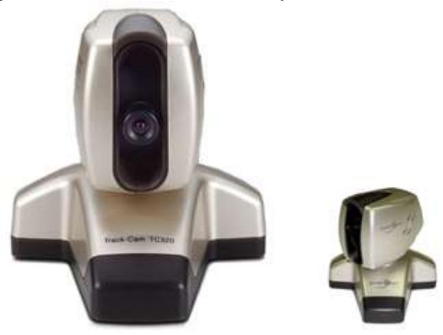
Pan and tilt camera
Pan and tilt Camera with a horizontal movement 180º and a heave 60º with the aid of software of obtains the image in the controller of the robot, [9]. Four megapixels is current resolution, this number cover our necessities for image caption; this camera is connected directly to embedded card using USB link.
Analog FM wireless camera
By the distortion of the noise of the digital camera was necessary to use an analogous wireless camera, some additional info may be founded in [8]. This camera uses FM to manage audio and video continuously from camera transmitter to receiver in the operator station.
8 Robot Locomotion
Our robot is composed by two rigid bodies and auxiliary bounds mechanism that support all mobile parts over displacement structure, this design is based into six wheels model depicted in [25], but some specific mechanics was adapted for our necessities. Obviously, electronically is quite different because our control programs and hardware is designed, to evaluate different strategies and necessities for rescue operations. In the Figure 8.1, show the body Robot, Total size of robot's world is 24x30 inches.
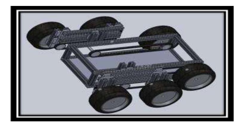
This robot has a structure body and tows mechanism with wheels, could be mobiles based into four links, see the Figure 8.2
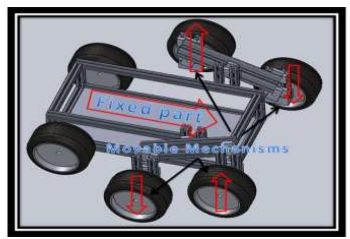
Transmission
Robot can move through a transmission whit 5 gear and tow Pulleys as show in the Figure 8.2, all of them have a relation of 1:1. Thus when the motor gives a turn, all the gears gives it.
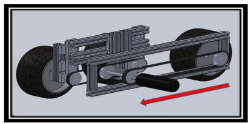
The mail idea was taken of the six wheels strategy, this model is ideal for hard ways, we only modify the internal structure of robot, with our sensors and actuators
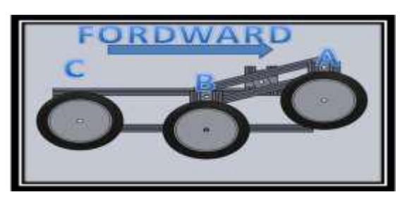
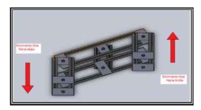
We can see the movement of the wheels, the wheel C is fixed while the wheel A and B can UP and Down respectively. Table show how is the movement about wheels A and B
Table 5. Symmetrical movement of 4 bounds mechanism.
| A | B |
|---|---|
| UP | Down |
| Down | UP |
The robot counts on 2 motors DC (12V) used to send traction in the bands of the Tires. When we want Turn Right, the motor A run Forward and the motor B run backward but if we want turn left the motor B run Backward and the motor. Forward movement motors will transmit his torque wings rims by means of a system of gears.
Structure profile
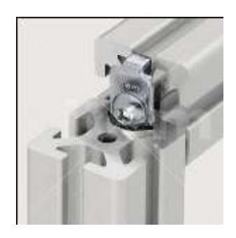
The five profiles are ideal for lightweight constructions of all kinds. The small exterior dimensions ensure particularly compact jigs, covers and handling equipment. The full functionality of the building kit is retained. For this reason we decided to use this material because it meets many of our needs for our project. The qualities and tolerances are described to assess the efficiency of this material. Automatic and manual fastener was applied to fit all structure to give structural enforcement and shape.
Pulleys and toothed Belts
The toothed pulleys are not dependent on friction to transmit power, allowing minimal stress on the bands. Moreover, by failing to slip between the pulley and the band, there is synchronization between the axles. Among the technological highlights the change in the profiles of the teeth of the pulleys and belts for transmissions offer increasingly silent and durable.
The pulleys can have straight teeth step in inches, MXL series (1 / 12 "), XL (1 / 5"), L (3 / 8 "), H (1 / 2"), XH (7 / 8 " ) and XXII (1-1/4 "), or series 3M, 5M, 8M, 14M and 20M, where the digits represent a move in millimeters.
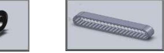
Main body of Robot
The material changes are too much benefit the project in its design and speed of assembly, Profile No 5 was the material used. The new material provides strength and stability to the robot land, now we will ensure that in the places where our robot ay natural disasters will remain stable and solid in any situation.
System Front
This system design was made an improvement, with which gives us more confidence in the stability and rigidity of our robot. Each crossing point is attached by bearings that allow you to have a free motion, another section was added which will allow you to drive mechanisms within the system. With the implementation of toothed belts and pulleys we have a very good response in the pull of the mechanisms in the figure shows the manufactured part in design software
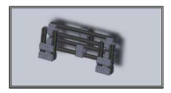
The creation of the second central axis was performed with the aim that the robot can carry out search work in places inaccessible to people specialized in finding people, now we have our security robot that no part will be exposed to suffer engine damage in any exhibition or test to perform because the majority of assemblies are inside the structure. Next figure shows how the incorporation of the second central axis is of great importance for the performance of the mechanism.
Rescue Robot Model and Views
Above figure shows the robot body, the total size of the robot in real mode is 24 x 30 inches.
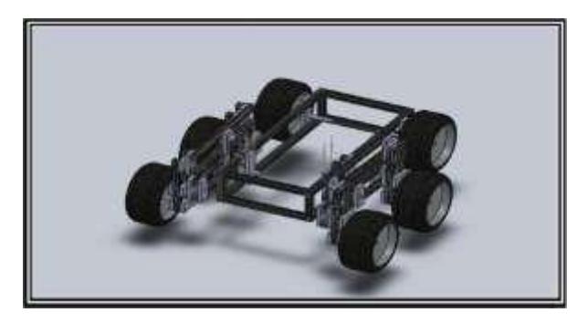
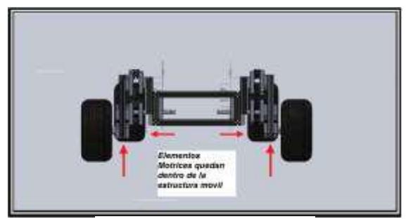
We will show a presentation of front and side views of the robot assembly, and to appreciate better the changes in design. The figure below shows on a hard hitting and will appreciate our Robot in the moving part of the tires are internal mechanisms, protecting them from blows or shocks in the field.
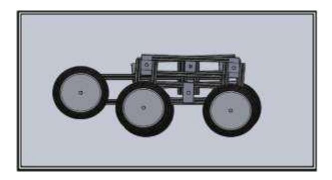
The figure below show a side view with which we appreciate that the design is constructed from the moving parts and a fixed rear axle. The height of the wheels on the ground is calculated to provide a better performance in field tests where you would cross paths highlight obstacles and deformed.
9 Other Mechanisms
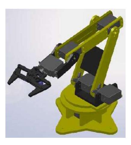
The robot counts with pan /tilt integrated camera, mounted over 6 DOF robot integrated into robot structure. This additional robot is take visual auxiliary support to find victims and take some light pieces to facilitate robot displacement and visual contact. This robot is previously designed by commercial manufacturer MECATRON-1, but is prepared to be mounted into CuerBot structure.
10 Team Training for Operation (Human Factors)
In order to operate the system of the Cuerbot in the movement aspect, it is necessary to know where one is its point of balance and its different movements, as well as its length, speed and the distance of turn in the direction. In addition to its different functions as they are, the form to elevate the dynamic camera, and as is its length of elevation; the form to interpret the values of the different sensors, like: infrared, sensorial sensor of CO2, sensor of temperature, in addition to the proximity sensors that are located in the flanks, to the front and in the back part of the Cuerbot. Essential robot drive teaching is be developed either State Rescue Team and our Team.
11 Possibility for practical application to Real Disaster Site
We are currently working with FONLIN program and supported by Red Temática Robótica y Mecatrónica CONACYT with special sponsoring of Robotics Mexican Federation FMR that consider new projects with new technology and developing, the main goal is to give us tools to put this robot into market, and another thing is that we are working together with Emergency State Services to share training and provides of one robot for community service. Remember our objective is to try to solve a local problem in disaster events.
12 System Cost
See table below for system cost breakdown.
System Cost Total
| System cost total | |
|---|---|
| Concept (model) | Cost per piece |
| Absolute Encoder | $180 usd |
| Microcontroller | $3 usd |
| Gyroscope | $600 usd |
| Pan and Tilt Camera | $150 usd |
| Wireless camera | $80 usd |
| Netbook | $350 usd |
| IR Temperature Sensor | $1250 usd |
| CO2 Sensor | $317 usd |
| CD Motors for desplacement | $25 USD C/U |
| Batteries | $54 USD C/U |
| Pulley's Band | $200 usd |
| Metal structure to form body | $154 usd |
| Industrial PVC for mechanical support | $95 USD |
| Gears | $150 usd |
| Bearings | $15 usd |
| Lamps | $15 usd |
| IC circuits (average) | $10 usd |
| VHF Hand Radios | $60 usd |
| Access point | $95 usd |
| Proximity Sensors | $60 usd |
| USB Memory 8Gb | $40 usd |
| Accessories | $1257 usd |
| Robot 6 DOF | $1,200 usd |
| TOTAL COST APROX | $6,357 usd |
13 Lessons Learned
This is a new experience over develop a small, light and transportable robot because for a real application needs a robot with these facilities. Another important thing is our artificial intelligence application improvement based into embedded technologies, all experiences are good goals for new knowledge for this research group and give us an opportunity to support our bachelor and master degrees related (human resources and specific project related with companies). On the other hand another experiences was received about our internal support and re-engineering was applied. The most important value is our graduate students, this project give them an opportunity to develop knowledge into specific areas of robotics; this project has been generator of 6 bachelor degrees and master degree. We will aggregate more info about our experiences when we will be participating in this RoboCup 2013.
References
- Adam Jacoff, Elena Messina, Brian A. Weiss, Satoshi Tadokoro, and Yuki Nakagawa, Test Arenas and Performance Metrics for Urban Search and Rescue Robots, Proceedings of the 2003 IEEE/RSJ InU. Conference on Intelligent Robots and Systems Las Vegas. Nevada. October 2003, 3396-3403.
- Hiroaki Kitano, Satoshi Tadokoro, Koichi Osuka4, RoboCup Rescue Project: Challenges and Benchmark, Proceedings of the 2000 IEEE/RSJ International Conference on Intelligent Robots and Systems, 1886-1993.
- Ashraf Aboshosha, Adaptation of Rescue Robot Behaviour in Unknown Terrains Based on Stochastic and Fuzzy Logic Approaches, Proceedings of the 2003 IEEERSJ Intl. Conference on Intelligent Robots and Systems Las Vegas. Nevada ' October 2003, 2859-2864.
- Bryan M. Hudock, On the Development of a Novel Urban Search and Rescue Robot, United States Naval Academy, 451-455.
- A. Carbone, A. Finzi, A. Orlandini, F.Pirri, G. Ugazio, Situation Aware Rescue Robots, Proceedings of the 2005 IEEE International Workshop on Safety, Security and Rescue Robotics Kobe, Japan, June 2005, 182-188.
- H. N. Pishkenari, S. H. Mahboobi, and A. Meghdari, On the Optimum Design of Fuzzy Logic Controller for Trajectory Tracking Using Evolutionary Algorithms, Proceedings of the 2004 IEEE Conference on Cybernetics and Intelligent Systems Singapore, 1-3 December, 2004, 660- 665.
- Fumitoshi MATSUNO, Satoshi TADOKORO, Rescue Robots and Systems in Japan, Proceedings of the 2004 IEEE International Conference on Robotics and Biomimetics August 22 - 26, 2004, Shenyang, China, 12-20.
- Karnik NILESH, Mendel JERRY, Introduction to Type-2 Fuzzy Logic Systems, IEEE Proceedings of Fuzzy Systems, 1998, USA, 915-920.
- Bin-Da Liu, Chun-Yueh Huang, Design and Implementation of the Tree-Based Fuzzy Logic Controller, IEEE TRANSACTIONS ON SYSTEMS, MAN, AND CYBERNETICS—PART B: CYBERNETICS, VOL. 27, NO. 3, JUNE 1997, USA, 475-487
- Chuen LEE, Fuzzy Logic in Control Systems: Fuzzy Logic Controller-Part I, IEEE Transactions on Systems, Man, and Cybernetics, Vol. 20, no. 2 March/April 1990, USA, 404-418
- Chuen LEE, Fuzzy Logic in Control Systems: Fuzzy Logic Controller-Part II, IEEE Transactions on Systems, Man, and Cybernetics, Vol. 20, no. 2 March/April 1990, USA, 419-435
- Brox M., Gersnoviez A., Sánchez-Solano S., Baturone I., Controlador difuso para problemas de navegación en presencia de obstáculos fijos Proc. XIII Congreso Español de Tecnologías y Lógica Fuzzy, pp. 29-34, Ciudad Real, Sep. 22-29, 2006.
- Cabrera A., Sánchez-Solano A., Barriga, Brox P., Moreno-Velo F.J., Baturone I. Plataforma para el Desarrollo de Controladores Difusos como Sistemas Empotrados Proc. XII Congreso Español de Tecnologías y Lógica Fuzzy, pp. 177-182, Jaén, Sep. 15-17, 2004.
- http://www.logitech.com/index.cfm/webcam_communications/webcams/devices/3480&cl=us,en, web site at March 2008.
- http://www.infokrause.com/camara_vivotek_FD7131_dual_codec_poe_ik.htm , web site at March 2008.
- http://www.pc-adictos.com.ar/hardware/de/tc-320.html, web site at March 2008.
- https://www.sealevel.com/uploads/manuals/3544.pdf, web site at March 2008.
- http://www.pc104.org/cgi-bin/detail_pc104.cgi, web site at March 2008.
- http://us.kontron.com/downloads/manual/BQBAM113.pdf, web site at March 2008.
- http://www.analog.com, web site at October 2008.
- http://www.maxim-ic.com, web site at October 2008.
- http://www.imse.cnm.es/Xfuzzy/, web site at November 2008.
- http://www.ohloh.net/p/SimForge, web site at January 2009.
- http://www.ida.liu.se/labs/pelab/modelica/OpenModelica.html, web site at January 2009.
- http://www.volksbot.de/robots.php, web site at January 2009.