RoboCupRescue 2013 - Robot League Team Kauil-TecMTY (Mexico)
Laura Galindez-Olascoaga, Rafael Balderas-Hill, Alejandro Aceves-López, Santiago Leon-Ortiz, Miguel Ángel Gálvez-Zúñiga
Tecnológico de Monterrey Campus Estado de México Carretera Lago de Guadalupe Km. 3.5, Atizapán de Zaragoza, Edo. de México. Gaithersburg, MD USA 20899
http://www.cem.itesm.mx/cms/kauil/ · http://www.itesm.mx
Abstract This Team Description Paper presents the current development of the Kauil-TecMTY Rescue robotics project. It presents the previous work done, the improvements performed on Kauil robot which participated in Robocup Rescue 2012 and the development of a new robot and its manipulator. All the control systems of the current version of Kauil-TecMTY Rescue robotics system are being developed and implemented in the Robot Operating System (ROS). The system is currently teleoperated and this year's main objective is to develop a multi robot framework in which one of the robots will be teleoperated and the second one will be autonomous.
Introduction
In 2007 the Mobile Robotics Laboratory at Tecnológico de Monterrey Campus Estado de México began its path towards the development of robotics systems for support in rescue activities on disaster scenarios. This application is of very high relevance in Mexico due to the region's high seismic activity. The main objective that is being pursued through this project is to create all-terrain intelligent agents capable of exploring disaster zones while displaying the status of the environment and locating victims in order to give the rescuers involved an insight on the strategies to undertake. The rescue system should be able to perform Simultaneous Localization and Mapping (SLAM), derive multi-robot navigation strategies, tag and classify victims, detect optimum trajectories to reach areas of interest and perform a general assessment of a disaster area.
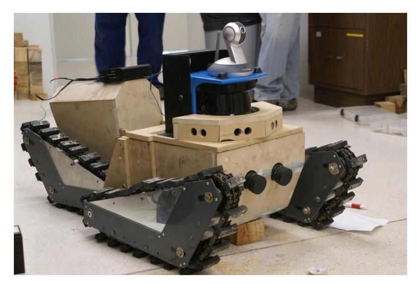
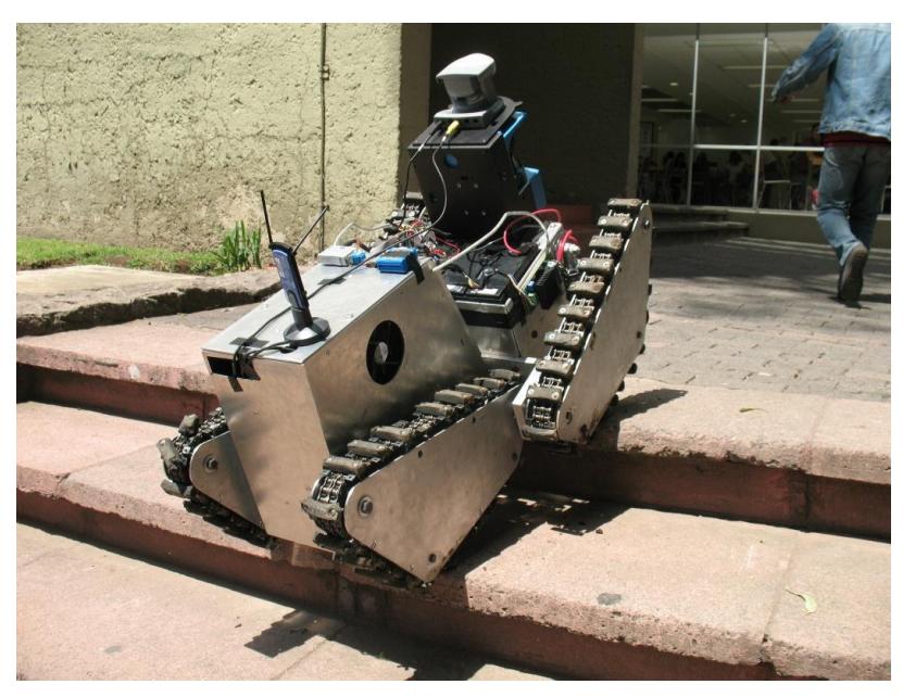
2007 was the year that witnessed the birth of the first rescue team's robot Nautilus which was presented in the Latin American Robotic Contest (LARC) 2007 in Monterrey, México. As depicted on Figure 1 Nautilus was a wooden prototype whose purpose was merely demonstrative. It was later redesigned to yield a more functional and robust system and whose given name is Kauil as depicted on Figure 2. This robot's structure is mainly made of aluminum, includes a more stable power train, and refined features to support a computer, sensors and interfaces. Kauil robot participated in Robocup Rescue China 2008 where the team focused on searching victims throughout the red zone arena, and managed to find one victim in the last run.
After evaluating the performance of the robot during the competition of 2008, several areas of improvement were identified, however the rescue robotics project at ITESM CEM was temporarily deactivated due to organizational issues inside the university. In 2011 the project was reactivated and some electronics and interfaces modifications were made to Kauil robot. In terms of software a significant reformulation of the control system was made and all the navigation algorithms and interfaces were programmed in the ROS.
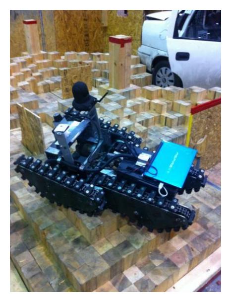
As depicted on Figure 3 the team participated in Robocup Rescue Mexico 2012 where Kauil robot navigated on the orange and red zones and was able to generate a map of them using a Rao-Blackwellized particle filter to solve the problem of SLAM. The main deficiencies of the system at this competition were the wireless communications technologies used as well as some limitations in terms of mechanical stability. For this reason the structure and function of Kauil's wireless communication systems are being reformulated and the central processor is being upgraded.
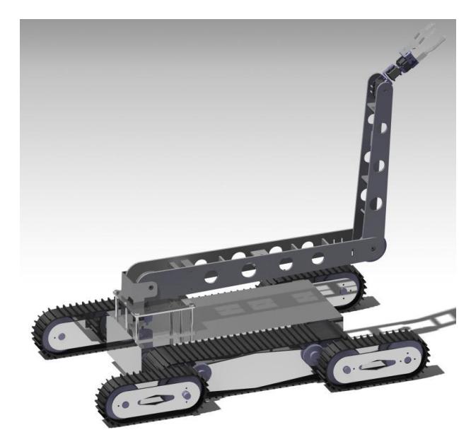
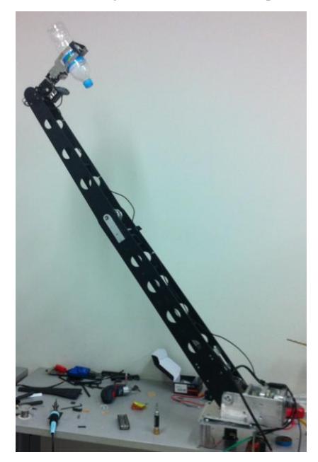
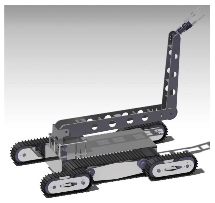
Moreover, a multi robot environment is starting to be implemented in order to assign tasks to each of the elements included according to its particular strengths. Complex mobility tasks are going to be undertaken by a new robotic platform which is currently under development and whose 3D render is shown on Figure 4 and whose given name is Xaac. New autonomous navigation algorithms are currently being developed and they will be implemented on Kauil robot. And finally, throughout 2012 a robotic arm was developed in order to participate in the manipulation challenges and aid in the victim identification and classification tasks as depicted on Figure 5.
The team's goal throughout 2013 is to complete all the projects that are currently under development in order to begin a more extensive research on navigation and control algorithms.
1. Team Members and Their Contributions
Kauil-TecMTY team is comprised by undergraduate students as well as some professors at Tecnológico de Monterrey Campus Estado de México.
Laura Isabel Galíndez Olascoaga Team leader/ SLAM, robot navigation. Rafael Balderas Hill Mechanical design, robot navigation.
Timothée Rene Givois Méndez Electronics design, wireless communications.
Caroline Siordia Campero Robotic arm assembly and operation. Miguel Ángel Gálvez Zúñiga Mechanical design and manufacturing. Juan Carlos Flores Mechanical design and manufacturing.
Santiago Leon Ortiz Electronics design, wireless communications.
Alejandro Aceves López Project director.
Cuauhtémoc Carbajal Fernández Electronics design advisor. Héctor Rafael Morano Okuno Manufacturing advisor.
Intel Mexico Sponsor.
We acknowledge the support and funding of ITESM-CEM as well as the unconditional support of Demetrio Galíndez Olascoaga, Carlos Nieto Granda and Diego Enrique Chavez Muñoz, former members of ITESM-CEM rescue robotics team, thanks to which the birth and development of this project has been possible until today.
2. Operator Station Set-up and Break-Down (10 minutes)
Our design intent is to have a backpack with a console game controller for remote operation, a laptop for monitoring of the mapping process and a second laptop for video streaming; the station will contain an omnidirectional antenna as well. A toolbox that will be used as an adjustable portable table is also going to be included.
3. Communications
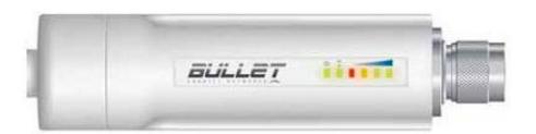
Communication with the robot will be made entirely through Wi-Fi. We plan to use 802.11a in the 5GHz band to avoid any interference from other devices that might be in operation during the competition. To accomplish this we will use an omnidirectional antenna equipped with Ubiquiti's Bullet M5 (Figure 6), configured in one of the lower band cannels for 802.11a (36 – 48). The robot's controller laptop will be also equipped with a NIC that supports the 5GHz band, like Netgear's HA501. Transmission of video from the IP cameras will be sent to the main PC through 2.4GHz Wi-Fi and then forwarded to the teleoperator's computer to give visual feedback and aid with the navigation of the arena, and using the more reliable 5Hz channel. Table 1 shows the features of our wireless communications system.
Wireless communications features
| Rescue Robot League | ||
|---|---|---|
| Kauil-TecMTY (MEXICO) | ||
| Frequency | Channel/Band | Power (mW) |
| 5.0 GHz - 802.11a | 36 - 48 | 200mW |
| 2.4 GHz - 802.11b/g | 11 | 100mW |
4. Control Method and Human-Robot Interface
A teleoperated control framework is currently being used for Kauil robot. For this year's competition a distributed architecture aided by the communication infrastructure provided by ROS is being proposed. The distributed architecture is composed mainly of four modules each of which has a central processor that was selected according to the specific task it has to perform.
4.1 System's Architecture
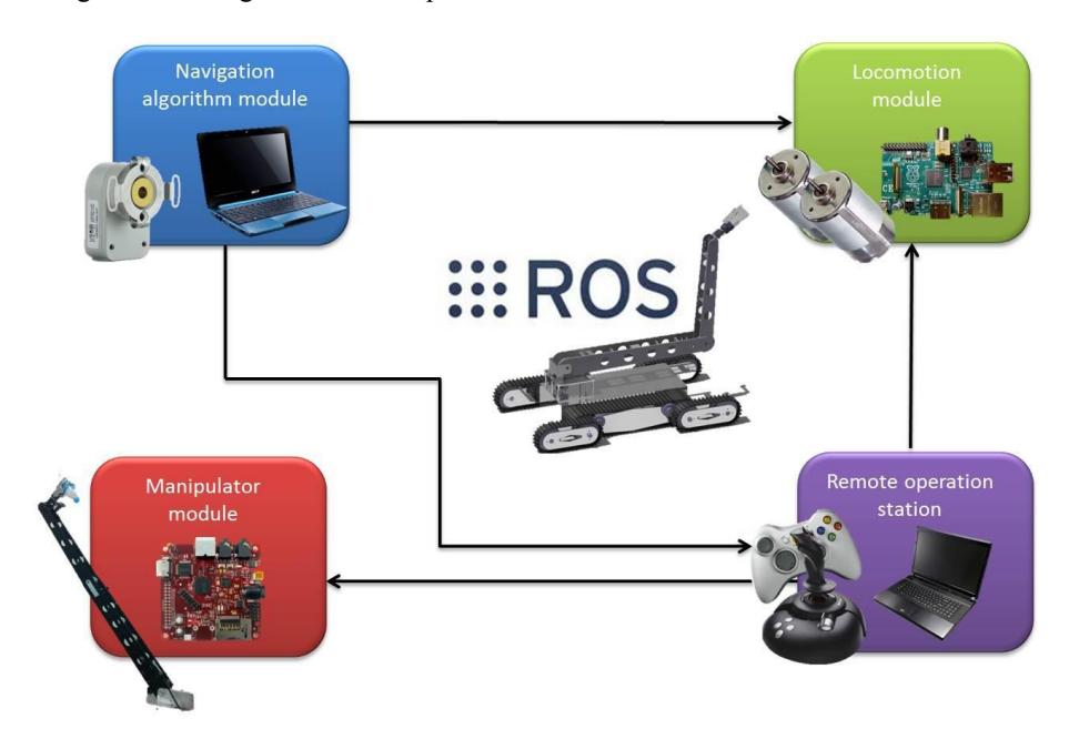
Figure 7 depicts the components of the system. The central processor of the locomotion model is a Raspberry Pi and its main role is to send the signals to the robot's DC motors in order for them to be activated whenever they receive a signal from the remote operation station. The remote operation station's central processor is a laptop whose task is acquiring signals from the remote control devices (a console game controller) and processing them in order to be then sent both to the locomotion module and the manipulator module. The manipulator module's central processor is a Beagleboard XM and its main role is controlling all the actuators and sensors involved in the manipulation, vision and sensing tasks that must be undertaken by the robotic arm. The last module in the system's architecture is the navigation algorithm one. Its central processor is an Acer Aspire One Netbook and it is in charge of acquiring the data of the robot's encoders and laser sensor in order for them to be processed by the navigation algorithms and generate the maps of the environment.
All the communications involved in the system are performed through a wireless peer-to-peer network of processes which is enabled by the ROS runtime "graph". The communication structure consists of a publisher and a subscriber which interchange messages contained inside topics.
The main reason why a distributed modular architecture was proposed is that our system is a low budget one and this distribution enables the usage of the available components without having to acquire a very high performance (and expensive) processor. Moreover, the fact that each one of the functions has a central processor assigned concentrates all the processor's resources in the specific task to perform.
We are proposing the same architecture for both Kauil and Xaac, the only substantial difference between these systems is that Xaac includes a robotic arm whereas Kauil does not.
4.1.1 Locomotion module: motor control
Motor control is achieved through the usage of two MD03 H-Bridge 24V 20 A motor drives. Data transmission from the central processor to the motor drives is achieved through serial communication using I$^2$C bus. A USB-ISS communications module is used to interface the central processor with the motor drives as depicted in Figure 8.
MD03 driver and USB-ISS interface possess a specific communication protocol that consists of hexadecimal byte chains. There are two main command chains included in the programmed driver. Table 2 shows the speed command data chain. This chain's sixth position is modified according to the data sent by remote operation station.. The speed range goes from 0x00 to 0xFF. Table 3 shows the direction command where the sixth position is as well modified by the data sent by the remote operation station. The driver's directions can be 0x00 for stop, 0x01 for forward and 0x02 for backwards.
A software driver was programmed in order to achieve the interface between the hardware components and ROS. The main task of this program is to receive data from the remote operation station and insert it in the command arrays that are then going to be sent to the MD03 driver via the USB-ISS interface.

Speed command hexadecimal chain
| 0x57 | 0x01 | 0x32 | 0xB0 | 0x02 | msg →speed | 0x03 |
|---|---|---|---|---|---|---|
| I2C direct mode | Start bit | Number of data bytes | Device's address | Speed register | (0x00 to 0xFF) Data | Stop bit |
Direction command hexadecimal chain
| 0x57 | 0x01 | 0x32 | 0xB0 | 0x00 | msg → direction (0x02 or 0x01) | 0x03 |
|---|---|---|---|---|---|---|
| I2C direct mode | Start bit | Number of data bytes | Device's address | Command register | Data | Stop bit |
4.1.2 Remote operation station
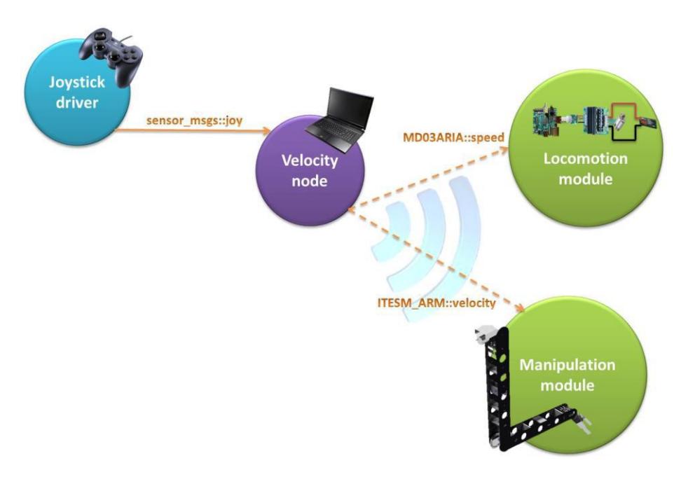
The remote operation station is comprised of a game console controller and a laptop as depicted on Figure 9. The game console controller sends messages to the laptop via USB. These messages are of type sensor_msgs::joy and include an array of float32 variables corresponding to the two joystick axes data and an array of int32 variables corresponding to the buttons data. The acquired data is processed inside the laptop which translates each of the joystick's data to two velocity commands, one for the robot's locomotion whose type is MD03ARIA::speed and one for the manipulator mode whose type is ITESM_ARM::velocity. Both commands are composed of a float32 variable for speed and an int32 variable for direction. It is important to mention that one of the controller's joysticks operates the manipulator and the other one operates the robot motion. In the case of Kauil robot the manipulator module is omitted.
4.1.3 Manipulator module
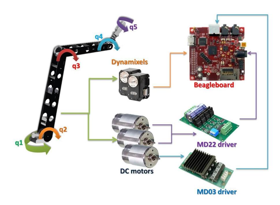
Figure 10 shows that the manipulator implemented has five degrees of freedom three of which are actuated by DC motors (q1, q2, q3). The other two degrees of freedom (q4, q5) are actuated by Dynamixel servomotors. The first and third degrees of freedom are controlled by a MD22 Dual 24Vo 5A H-bridge motor drive and the second one is controlled by a MD03 motor dive as depicted on Figure 10.
What should be achieved by the remote operation controller is a desired position of the final effector. The variable sent by the joystick is a position in (x,y,z) . The farther the joystick is pushed, the higher the speed at which the goal is going to be reached. Considering that the known information is the desired position in (x,y,z), the inverse Jacobian was used in order to calculate the derivatives of the desired angular positions for each degree of freedom as shown in Equations 1 to 5.
$$\begin{bmatrix} \dot{q}_1 \ \dot{q}_2 \ \dot{q}_3 \ \dot{q}_4 \ \dot{q}_5 \end{bmatrix} = J^{-1} \begin{bmatrix} \dot{x} \ \dot{y} \ \dot{z} \end{bmatrix}$$
Where
$$x = f_x(\dot{q}_1, \dot{q}_2, \dot{q}_3, \dot{q}_4, \dot{q}_5)$$
$$y = f_y(\dot{q}_1, \dot{q}_2, \dot{q}_3, \dot{q}_4, \dot{q}_5)$$
$$z = f_z(\dot{q}_1, \dot{q}_2, \dot{q}_3, \dot{q}_4, \dot{q}_5)$$
$$J = \begin{bmatrix} \frac{\partial f_X}{\partial q_1} & \frac{\partial f_X}{\partial q_2} & \frac{\partial f_X}{\partial q_3} & \frac{\partial f_X}{\partial q_4} & \frac{\partial f_X}{\partial q_5} \ \frac{\partial f_Y}{\partial q_1} & \frac{\partial f_Y}{\partial q_2} & \frac{\partial f_Y}{\partial q_3} & \frac{\partial f_Y}{\partial q_4} & \frac{\partial f_Y}{\partial q_5} \ \frac{\partial f_Z}{\partial q_1} & \frac{\partial f_Z}{\partial q_2} & \frac{\partial f_Z}{\partial q_3} & \frac{\partial f_Z}{\partial q_4} & \frac{\partial f_Z}{\partial q_5} \end{bmatrix}$$
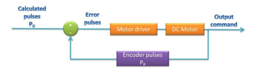
For each DC motor the closed loop framework depicted on Figure 11 is implemented.
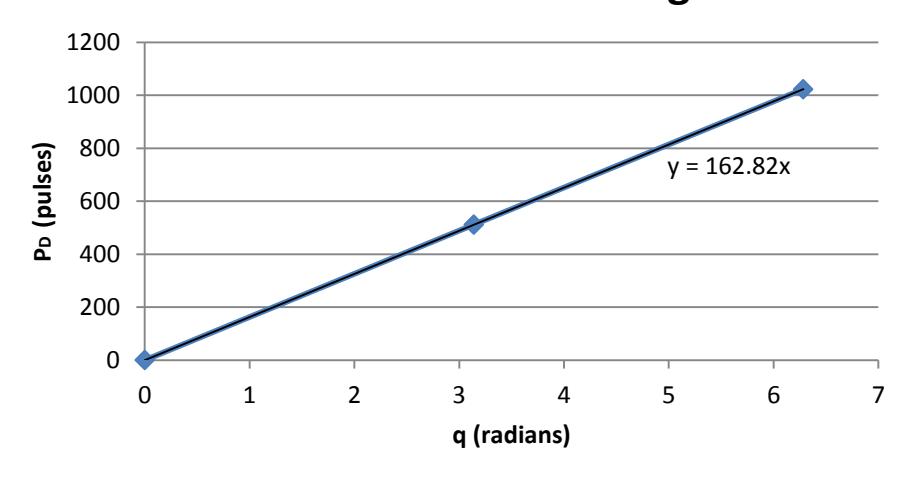
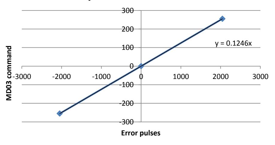
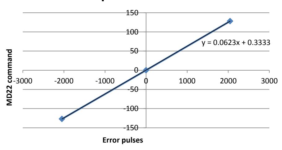
The calculated pulses are obtained from the linear regression shown in Figure 12 which takes into consideration the resolution of the encoders used (1023 pulses per turn).
4.1.4 Navigation algorithm module: ROS navigation stack
The Navigation Stack is provided by ROS and it is used to take information from odometry and sensor streams and it returns goal pose and velocity commands that are in accordance with these poses. The elements that enable the integration of this stack are the following [5]:
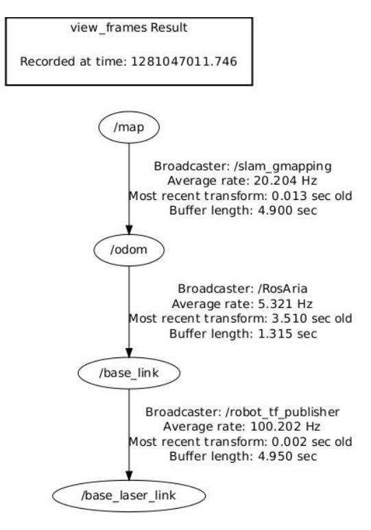
Transform configuration. There must be relationships between the different coordinate frames of the robot. Figure 15 shows an example in which odometry is provided by RosAria client and a map is generated using slam_gmapping package[8].
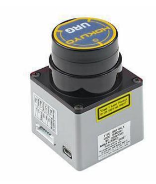
Sensor information. Our robots use a Hokuyo URG laser to get information that will later be used for obstacle avoidance. This sensor publishes a sensor_msgs/LaserScan topic and is configured in the base_laser_link frame as shown in Figure 15.
Odometry information. Odometry computation will be included in MD03ARIA package and is in accordance to the robot's kinematic model and characteristics.
Base controller. The navigation stack should be able to send velocity commands. This is achieved in our system by the usage of the MD03ARIA node.
Mapping (map_server). This node is provided by ROS and offers dynamically generated maps based on a series of data provided by odometry and sensor information.
AMCL package. This package includes the implementation of adaptive Monte Carlo localization[8] approach which uses a particle filter for pose tracking.
4.2 Human robot interaction
Human-robot interaction takes place mainly through the teleoperation process whose data is acquired through a game console controller as explained in the remote operation section.
The default graphical interface that ROS provides is named Rviz [8] and is used both for 2D and 3D visualization. At the current development stage, only 2D visualization has been achieved, however, the ultimate goal is to create 3D visualizations in order to model more reliably the transversability of the terrain and be more precise in the process of victim identification.
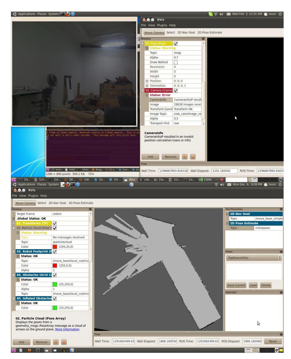
This visualization tool can be customized directly through the graphical interface or by writing configuration files. Rviz displays information according to the topics the user wishes to visualize. Figure 16 shows the visualization of usb_cam topic, laser topic, odom topic and map topic.
5. Map generation/printing
Our team's approach to the solution for Simultaneous Localization and Mapping (SLAM) [10] was to generate platform specific odometry calculations and integrate them with transformation of coordinate frames in order to implement a Modified RaoBlackwellized Particle Filter [12] for grid map generation. The Particle Filter's algorithm is provided by ROS, odometry calculations were performed with the use of a differential kinematic model [1] and the transformations between coordinate frames enable the laser's data to be analyzed with respect to the global reference frame (map)[1]. The tree of coordinate frames transformation is depicted on Figure 15.
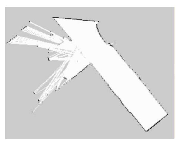
ROS's map_saver node enables us to print the resultant map in a .png image similar to the one depicted on Figure 17.
6. Sensors for Navigation and Localization
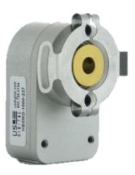
The input variable that is used in order to make all the Odometry´s calculations for the two robots is the pulse data provided by two quadrature encoders attached to the rotors as depicted on Figure 18. This data is then converted to linear displacements for each of the wheels.
A Hokuyo URG-04LX (Figure 19) is used for map generation along the mapping algorithm.
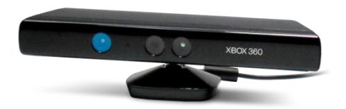
Microsoft's Kinect sensor (Figure 20) is used to implement a vision algorithm which is used for the odometry correction[14]. It is implemented through the selection of landmarks along the zone in order to have the most exact position of the robot. Then data from this odometry correction is sent to the algorithm of transformation between coordinate frames for map generation.
7. Sensors for Victim Identification
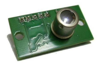
An infrared thermal Array Sensor (TPA81) is attached to the robotic arm in order to measure the heat temperature of the victim (Figure 21).
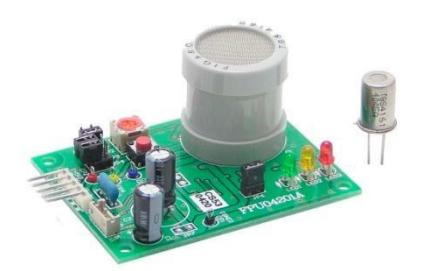
A CO2 (CDM4160) sensor (Figure 22) was implemented in the robotic arm in order to identify the CO$_2$ released by the human body of the victims.
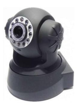
An IP based camera (FI8910W) is used to visualize the rear part of the robot depending on the scenario and the obstacles that the robot will face (Figure 23).
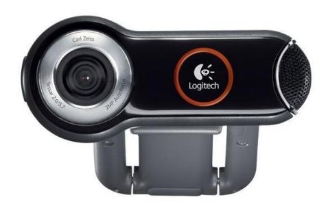
Logitech quickcam pro 9000 webcam (Figure 24) is attached yo the robotic arm, and it is used in the victim´s identification algorithm.
8. Robot Locomotion
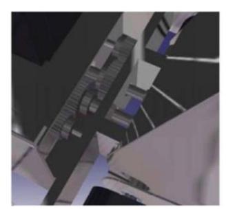
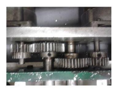
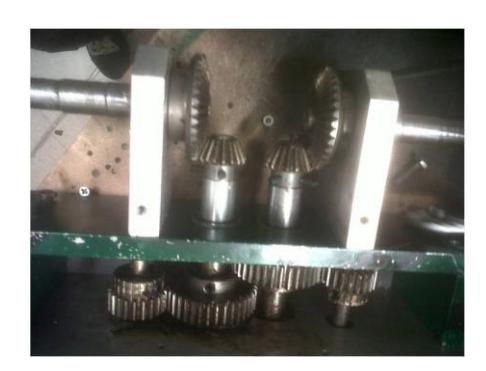
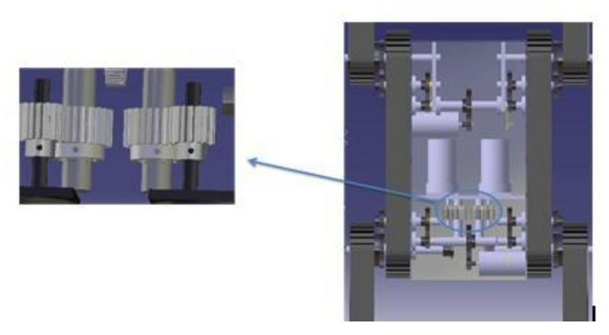
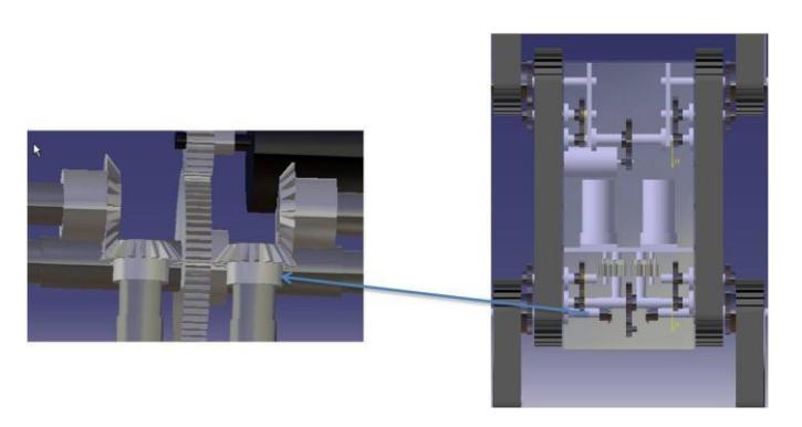
Kauil's locomotion consists of a gear train with two stages of reduction which satisfy the system's toque requirements. The first stage consists of a pair of spur gears and the second one consists of two bevel gears. Figure 25 and Figure 26 depict both stages, and Figure 27 shows the final configuration which designed according to the rough terrain's requirements and considering as well a 45° slope as the greatest obstacle to overcome. The specifications of the motors are shown in Table 4.
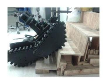
It is very important to mention that the second stage's objective is not only to transmit torque, but also to couple the transmission shaft to the sprockets of the track system which is depicted in Figure 27. The track system is composed of a double chain system with attached neoprene profiles intended to increase the frictional forces for better traction.
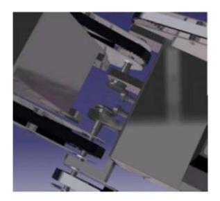
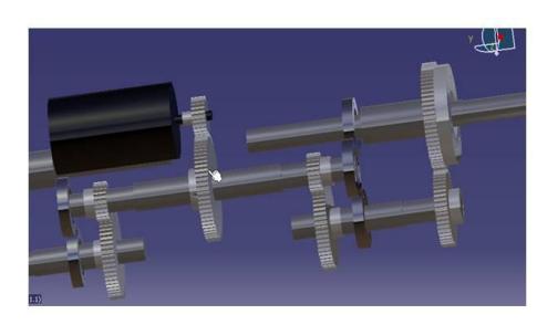
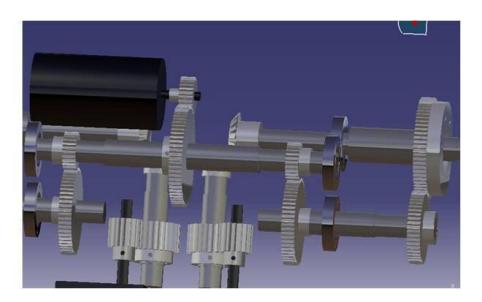
The main feature of the Xaac´s locomotion is the active flipper´s system it has, thank to which the robot maintains its stability which enables it to have an efficient mobility through rough terrains with uneven surfaces and to overcome obstacles with slope angles above 45°. The power system has a faster gear ratio that enables the robot to have advantages in speed. It is important to mention that there are two transmission systems. The first one for the locomotion of the robot with two stages of reduction and the second one for the flippers movement with three stages; the power system of Xaac is depicted in Figure 28 and Figure 29 while the transmission system of the flippers is depicted in Figure 30. Finally, the track system consists of a rubber track-pulley combination to have an efficient mobility when the robot is climbing with the robotic arm mounted (Figure 31).
DC motors' features
| Full Load Torque | Nominal Rotational Speed | Nominal Voltage | Nominal Current | |
|---|---|---|---|---|
| DC motors | 18.14Nm | 333rpm | 32.4 V | 3 A |
Torque in the first stage of reduction
| Number of teeth of pinion | Number of teeth of gear | Relation | Pinion Torque [Nm] | Gear Torque [Nm] |
|---|---|---|---|---|
| 22 | 38 | 1.727:1 | 18.14 | 31.33 |
Torque in the second stage of reduction
| Number of teeth of pinion | Number of teeth of gear | Relation | Pinion Torque [Nm] | Gear Torque [Nm] |
|---|---|---|---|---|
| 17 | 37 | 2.1764:1 | 31.33 | 68.2 |
Final torque to overcome the obstacles
| Ratio | Torque per transmission [Nm] | Final Torque [Nm] |
|---|---|---|
| 4:1 | 68.2 | 136.4 |
Torque in the first stage of the Xaac's locomotion
| Number of teeth of pinion | Number of teeth of gear | Relation | Pinion torque [Nm] | Gear torque [Nm] |
|---|---|---|---|---|
| 16 | 25 | 1.56:1 | 18.14 | 28.39 |
Torque in the second stage of Xaac's transmission
| Number of teeth of pinion | Number of teeth of gear | Relation | Pinion torque [Nm] | Gear torque [Nm] |
|---|---|---|---|---|
| 20 | 25 | 1.25:1 | 28.39 | 36 |
Final torque of transmission of flippers
| Torque required [Nm] | Motor's torque [Nm] | Relation | First stage | Second stage | Third stage |
|---|---|---|---|---|---|
| 24 | 2.47 | 10:1 | 2.8:1 | 2.4:1 | 1.4:1 |
9. Other Mechanisms
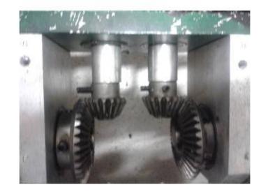
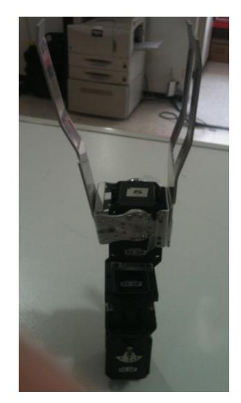
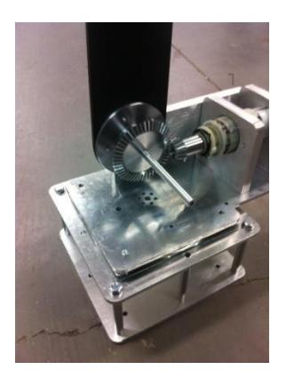
The locomotion of the robotic arm consists of two couple of bevel gears in order to have the required torque to pick up a water bottle to aid the victims. Figures 32 and 33 depict the locomotion system and gripper system.
10. Team Training for Operation (Human Factors)
The teleoperation program enables the user to send the desired command through the use of the operation station's joystick which works in ROS, so the team will be using the standard HMI of ROS and will perform the adequate modifications to make the system operable and adjustable to rescue related users. Therefore, basic knowledge of a Linux based operating system is required to successfully operate the robot.
11. Possibility for Practical Application to Real Disaster Site
Kauil can very efficiently navigate through uneven terrains which have a lot of obstacles with different geometries and shapes, so our mechanical system could be subjected to a practical application, however the neoprene profiles of our track system would wear down. That is the reason why we are implementing rubber tracks for Xaac. On the other hand we changed some iron materials of the robot structure to aluminum in order to increase the speed of the robot, and this to ensure a good speed across the disaster zone.
Xaac can be easily used in a real disaster zone for mobility and teleoperation tasks because it has an active suspension system that keeps its stability and it has a manipulator with a camera and temperature sensor to identify victims and to aid them.
Mexico suffers from several earthquakes every year. After the huge earthquake of 1985, a civil association called "the Topos of Tlatelolco" has been supporting Mexico and other countries in the event of a disaster. Our mid-term goal is to implement a multi robot working environment using Xaac and Kauil in order for this organization to evaluate the efficiency of our models and their possibility of practical application.
System's cost
| Quantity | Part number | Price (US dollars) | Total (US dollars) |
|---|---|---|---|
| 2 | USB-ISS interface | 39.92 | 73.85 |
| 2 | FOSCAM FI8910W | 93.99 | 187.98 |
| 4 | MD03 motor drive | 116.15 | 464.6 |
| 9 | LiPo rechargeable battery 12V 4Ah | 45 | 405 |
| 3 | Nylamid plate 1/2 inch | 92.31 | 276.93 |
| 4 | Encoder | 150 | 600 |
| 1 | Hokuyo URG | 2375 | 2375 |
| 2 | DC motor 32.4 V | 35.5 | 71 |
| 3 | Aluminum bar 1800mm long, 1 in dia. | 6.65 | 19.95 |
| 3 | Aluminum bar 300mm long, 1.5 in dia. | 6.65 | 19.95 |
| 6 | Ball bearings SKF 6002-2RSH | 5.04 | 30.24 |
| 4 | Bevel gears | 48.52 | 194.08 |
| 4 | Spur gears | 23.33 | 93.32 |
| 2 | Cylindrical Roll Bearings | 26 | 52 |
| 5 | Double chains conveyors | 124.47 | 622.35 |
| 12 | Sprocket P40-2 | 35.46 | 425.52 |
| Total | 5911.77 |
| | | | |
| Quantity | Part number | Price (US dollars) | Total (US dollars) |
|---|---|---|---|
| 2 | DC motor 32.4 V | 35.5 | 71 |
| 2 | DC motor 12 V | 25 | 50 |
| 4 | rubber tracks 757mm long | 72 | 288 |
| 2 | rubber tracks 1377mm long | 130 | 260 |
| 12 | aluminum pulleys | 75 | 900 |
| 1 | aluminum plate | 250 | 250 |
| 24 | spur gears | 50 | 1200 |
| 4 | bevel gears | 40 | 160 |
| 30 | Ball bearings | 5.04 | 151.2 |
| 2 | Aluminum bar 1000mm 3/8 in | 23 | 46 |
| 2 | Aluminum bar 1000mm 7/8 in | 15 | 30 |
| Total | 3406.2 |
| | | | |
| Quantity | Part number | Price (US dollars) | Total (US dollars) |
|---|---|---|---|
| 1 | DC motor 18 V | 290 | 290 |
| 2 | DC motor 12 V | 176 | 352 |
| Aluminum material | 72 | ||
| Ball bearings | 50 | ||
| Brackets Trossen Robotics | 190 | ||
| Electronic | 35 | ||
| Sintra material | 60 | ||
| 4 | Bevel gears | 49.25 | 197 |
| Total | 1246 |
12. System Cost
(System cost breakdown as shown in tables above)
References
- S. Delbouis-Fuentes, L. Galíndez-Olascoaga, R. Balderas-Hill, K. Herrera, C. Sánchez-Hernández, E. Flores-García, A. Aceves-López, C. Carbajal, Simplified Navigation Model for a Rescue Robot. In Proc. of the AMRob. Congreso Mexicano de Róbotica, 2008
- K. Ohno, S. Morimura, S. Tadokoro, E. Koyanagi, T. Yoshida, Semi-autonomous Control System of Rescue Crawler Robot Having Flippers for Getting Over Unknown-Steps, Proceedings of the 2007 IEEE/RSJ International Conference on Intelligent Robots and Systems San Diego, CA, USA, Oct 29 - Nov 2, 2007
- C. Nieto-Granda, D. Galíndez-Olascoága, D. Chávez-Muñoz, C. Camargo-Rosas, A. Arriaga-Orta , Design of An All Terrain Mobile Robot for Indoor and Outdoor Search and Rescue Tasks, In IEEE/RSJ International Conference on Intelligent Robots and Systems, 2008
- C. Nieto et al. Nautilus Robot Rescue League Team, Latin American Robotics Contest 2007, IEEE, ISBN: Pending
- L. Galindez-Olascoaga, A. Aceves-Lopez, C. Nieto-Granda, D. Chávez-Muñoz, D. Galíndez-Olascoaga, RoboCup Rescue 2012 . Robot League Team – Kauil-TecMTY. Team Description Paper for 2012 Robocup Rescue. Mexico City, Mexico.
- J. Shigley's, C. Mischke, R. Budynas, J. Nisbett, "Shigley´s Mechanical Engineering Design", McGraw-Hill, USA, 8th, 2008.
- R. Mott, "Diseño de Elementos de Máquinas", Pearson, México, 2006.
- K. Conley (2012). ROS Introduction. [Online]. Available: http://www.ros.org/wiki/ROS/Introduction
- H. Durrant-White, T. Bailey. Simultaneous Localization and Mapping: part I. IEEE Robotics & Automation Magazine. Pages 99-110. 2006.
- J.J. O'Reilly. SLAM I tutorial. Simulation Conference, 1990. Proceedings. Winter, 1990.
- S. Thrun, W. Burgard, D. Fox, "Probabilistic robotics", MIT Press, Boston, 2005
- G. Grisetti, C. Stachniss, W. Burgard. Improved Techniques for Grid Mapping with Rao-Blackwellized Particle Filters, IEEE Transactions on Robotics, 2006.
- G. Grisetti, C. Stachniss, W. Burgard. Improving Grid-based SLAM with Rao-Blackwellized Particle Filters by Adaptive Proposals and Selective Resampling. In Proc. of the IEEE International Conference on Robotics and Automation (ICRA), 2005.
- Moreira, M.A.G Mobile robot outdoor localization using planar beacons and visual improved odometry. IEEE/RSJ Intelligent Robots and Systems(IROS) , 2007.