RoboCupRescue 2013 – Robot League Team SocRob-RESCUE
Filipe Jesus, Jo˜ao Mendes, Henrique Silva, Rodrigo Ventura
Institute for Systems and Robotics Instituto Superior T´ecnico Av. Rovisco Pais, 1 1049–001 Lisboa; Portugal
Abstract This Team Description Paper presents the current status of the SocRob-RESCUE team. Two robots are used: RAPOSA-NG, a tracked wheel robot equipped with cameras and range sensors, and a Quadrotor, equipped with a camera and a range sensor. These robots are fully teleoperated, using a wireless link. The goal of the quadrotor is to build an elevation map to aid the guidance of the land vehicle. The main improvements being introduced are: (1) 2D map building using SLAM techniques, (2) elevation mapping from the air using bundle adjustment techniques, and (3) use of a zoom camera to capture detailed information from the victims.
Introduction
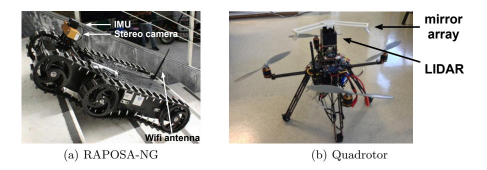
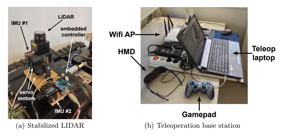
The SocRob-RESCUE team had its first participation in international competitions in RoboCup German Open 2012, where it achieved 5th place in 10 and was qualified for the best-in-class in mobility. We used a tracked wheel vehicle, RAPOSA-NG (see Figure 1a), fully teleoperated. In RoboCup 2013 we intend to participate with two robots: RAPOSA-NG, improved with a LIDAR sensor for map building and localization (shown in Figure 2a), and a Quadrotor (Figure 1b), for building an elevation map of the environment. The following sections describes our team in further detail.
1 Team Members and Their Contributions
The SocRob-RESCUE team comprises the following members:
Rodrigo Ventura — Team leader Filipe Jesus — Software development, operator (RAPOSA-NG) Jo˜ao Mendes — Hardware development (RAPOSA-NG) Henrique Silva — Quadrotor development and operator
This work was supported by FCT projects PEst-OE/EEI/LA0009/2011 and PTDC/EIA-CCO/113257/2009.
2 Operator Station Set-up and Break-Down (10 minutes)
The RAPOSA-NG robot can be transported by 2 persons. The operator station comprises the following components (shown in Figure 2b): (1) conventional laptop computer (Asus N53S Se-ries), (2) Head-Mounted Display with an integrated head tracker (Vuzix iWear VR920), (3) WiFi access point (Cisco AIR-AP1252AG-E-K9), (4) gamepad (Logitech Dual Action), (5) R/C remote control. Components (1-4) are physically bundled together to a wooden board, with a single power plug, so that they can be easily transported to the operator site (1 person is enough for its transport). Component (5) is hand-held by the quadrotor operator and is battery powered. The set-up procedure includes connecting a single power plug and power on the RAPOSA-NG robot. The whole procedure takes typically less than 3 minutes.
The communication with RAPOSA-NG relies on WiFi. We are capable of using either 802.11a (5GHz band) or 802.11b/g (2.4GHz band), using consumer market equipment. There is a WiFi access point to which RAPOSA-NG connects to, which provides wired connection to the operator laptop.
The quadrotor operates on the 2.4GHz band, both for the R/C and for datalink via ZigBee.
3 Control Method and Human-Robot Interface
Both robots are fully tele-operated. The RAPOSA-NG robot is operated using an HMD, receiving a stereo video stream from the robot, captured by a stereo camera pair mounted on a motorized pan&tilt mounting. The integrated IMU inside the HMD allows orienting the cameras according to the operator head orientation. Thus, the cameras orientation is directly adjusted by the operator head movement, while the operator hands are free to control robot motion from the gamepad (as well as any other operation on the remote laptop). This arrangement allows the decoupling between camera orientation control and robot motion control. The quadrotor is controlled by a conventional R/C handheld station.
4 Map generation/printing
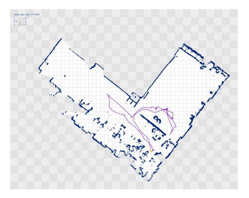
Mapping is based on the well-known Hector SLAM package for ROS (illustrative example shown in Figure 3). A LIDAR sensor on a tilt&roll mounting is used to obtain range data and a IMU is used to obtain inertial data. The LIDAR mounting is used to: (1) stabilize the LIDAR attitude so that the range data is obtained at an horizontal plane (an IMU is used to close the control loop), and (2) obtain 3D point clouds for 3D mapping by changing the LIDAR orientation in a continuous way.
The quadrotor is equipped with an onboard LIDAR and camera. The camera is used to obtain aerial images that are used to construct both the terrain elevation mapping and to reconstruct the vehicle trajectory, using an off-the-shelf bundle adjustment software package. The LIDAR is used to collect 3D pointclouds that are registered offline, using the vehicle position tracking obtained above.
5 Sensors for Navigation and Localization
Localization of RAPOSA-NG is obtained in real time from the Hector SLAM package. Currently, localization of the quadrotor is only available offline, after running the bundle adjustment package over the images collected airborne.
6 Sensors for Victim Identification
Victim identification is performed using the cameras onboard RAPOSA-NG: the stereo pair is wide-angle, thus allowing the identification of potential victims, while the zoom camera is used to gather detailed visual information from the detected victims. The captured images are also used for QR decoding.
7 Robot Locomotion
The RAPOSA-NG is a tracked wheel vehicle actuated by DC motors. It is comprised of a main body, with two tracks, mechanically coupled to an articulated frontal body. This frontal body also has two tracks. The robot is powered by two LiPo battery packs, decoupling the motors power source from the electronic.
8 Team Training for Operation (Human Factors)
The teleoperation of RAPOSA-NG is very intuitive. All motors/movements of the robot can be fully controlled using a 4 axis joypad and, as mentioned above, the decoupling between the robot and the camera control offers the user the possibility of controlling the camera with a single head movement.
On the other hand, the quadrotor requires extensive training and an experienced pilot.
9 Possibility for Practical Application to Real Disaster Site
Our experiences with RAPOSA-NG in prior tests and in German Open 2012 enable us to conclude that our solution is stable and usable in real world scenarios. Further improvements include the implementation of autonomy as the robot is, at the moment, fully tele-operated and relies on base-robot communication.
10 System Cost
The RAPOSA-NG is based on a commercial platform with the same name offered by IdMind (www.idmind.pt). The cost of the base platform is about 15kEUR. All onboard computation, sensors, etc. were integrated from consumer products. The most relevant components are the stereo camera (PointGrey BumbleBee2, about 2kEUR), the pan&tilt mounting (ServoCity SPT200, about 50EUR), and the LIDAR (Hokuyo URG-04LX-UG01, about 1kEUR). The tilt&roll mounting for the LIDAR was custom built using a 3D printer.
11 Lessons Learned
During German Open 2012, our team acquired new expertise and knowledge from the competition. Some measures were applied after the competition to prevent common problems, such as strengthening some electrical connections and incorporating new watchdogs (e.g. WiFi connection, Pan&Tilt microcontroller communications). Also, some tele-operation controls were improved for better mobility.
References
- Vieira, P., Ventura, R.: Interactive mapping using range sensor data under localization uncertainty. In: International Workshop on Perception for Mobile Robots Autonomy (PEMRA'12), Poznan, Poland (2012)
- Vieira, P., Ventura, R.: Interactive 3D scan-matching using RGB-D data. In: IEEE International Conference on Emerging Technologies and Factory Automation (ETFA'12), Krak´ow, Poland (2012)
- Jesus, F., Ventura, R.: Combining monocular and stereo vision in 6D-SLAM for the localization of a tracked wheel robot. In: IEEE International Symposium on Safety Security and Rescue Robotics (SSRR'12), College Station, TX (2012)
- Vieira, P., Ventura, R.: Interactive mapping in 3D using RGB-D data. In: IEEE International Symposium on Safety Security and Rescue Robotics (SSRR'12), College Station, TX (2012)
- Jesus, F., Ventura, R.: Simultaneous localization and mapping for tracked wheel robots combining monocular and stereo vision. In: International Workshop on Perception for Mobile Robots Autonomy (PEMRA'12), Poznan, Poland (2012)