RoboCup Rescue 2015 - Robot League Team BART LAB Rescue Robotics Team (Thailand)
Jackrit Suthakorn, Ph.D., Sakol Nakdhamabhorn, Chawaphol Direkwatana, Syed Saqib Hussain Shah, Choladawan Moonjaita, Peerapat Owatchaiyapong, Rachot Phuengsuk, Shen Treratanakulchai, Maria Chatrasingh, Preedipat Sattayasoonthorn, Nantida Nillahoot, Karat Thanaboonkong, Branesh Madhavan Pillai, Pittawat Thiuthipsakul, Korn Borvorntanajanya, Suwipat Chalongwongse
Center for Biomedical and Robotics Technology (BART LAB) Faculty of Engineering, Mahidol University; 25/25 Putthamonthon 4 Road, Salaya, Nakorn Pathom 73170 THAILAND
Abstract BART LAB Rescue Robotics Team, a RoboCup Rescue Robotics team from Thailand, has participated in regional robot competitions since 2006. Since 2006, the team has received various awards for its robots. The team has also received acclaim during its participation in various international events. The team consists of three robots; two tele-operative robots and one autonomous robot. Their highly mobile attribute is a result of the four independently controlled flippers of the robots. The tele-operative robots are controlled using a controller while the autonomous robot navigates itself through the arena using a laser-scanner. The robots have similar physical structures and systems. The system used for mapping is SLAM whereas the one used for locomotion is the fuzzy logic algorithm. On the other hand, the physical structures consist of a platform and manipulator, where the manipulator contains the sensors required for victim detection. The main goal of our research and development team is to produce reliable rescue robots to employ in a real disaster situation around the world.
Introduction
'BART LAB Rescue Robotics Team' is a one of rescue robotics team from Thailand and presently consists of sixteen members and two robots. The two robots are composed of one Tele-Operative robots (TeleOp V) and one autonomous robot (AutoBot III). We constantly researching and developing robots and has participated in regional robot competitions since 2006.
In 2008, Thailand Rescue Robot Championship (TRR 2008), we were one of the 8-finalist teams from 80 plus participating teams and received the Best-In-Class award for its autonomous robot. In early 2009, we attended the RoboCup Japan Open 2009 in the Rescue League with ten Japanese teams, where the team received second place. Additionally, we were awarded the 'SICE Award" for data collection and management of the autonomous robot.
At the 2009 Thailand Rescue Robot Championship (TRR 2009), we were the Winner and awarded Best-in-Class for its autonomous robot. TRR 2009 was one of the most competitive Rescue Robot League in the Work with more than 100 exceptional teams, consisting of six international teams from four countries (Australia, NuTech-R: Japan, NIIT-Blue: Japan, Jacobs University: Germany, Pasargard: Iran, and Resquake: Iran). In early 2010, the team attended RoboCup Japan Open 2010 was awarded 1 st Place Rescue Robot Award. After commendable performance at these two competitions, we participated at World RoboCup Rescue 2010, Singapore as the official representative team. There, the team was awarded the 1 st runner-up for its Rescue Robot.
In 2011 to 2015, the our team continued to receive awards, 1st Place Rescue Robot Award and 1st Runner-up Rescue Robot Award at RoboCup Japan Open 2011 and 2012, respectively. Furthermore, the team was awarded the Best Autonomy Award at Thailand Robot Championship 2012 in the Rescue Robot League, 3rd Place Rescue Robot Award at World RoboCup Rescue 2014, Brazil. In early 2015, the team attended RoboCup Iran Open 2015 was awarded 3rd Place Rescue Robot Award.
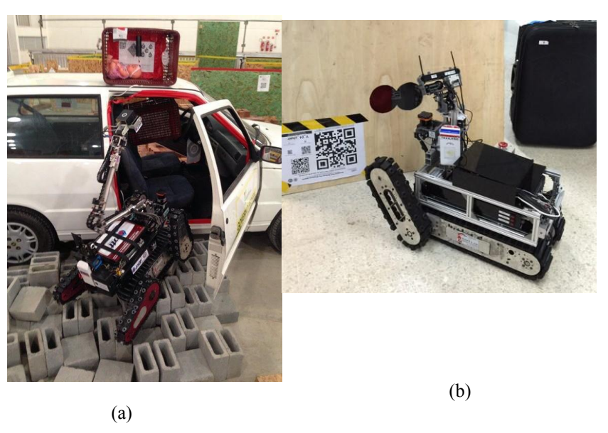
Tele-operative robot similar in their design yet have different performance, since TeleOp IV has better driving components. Tele-operative robots are highly mobile robots with tracking locomotion systems, making the robots more mobile in orange and red arenas. The robots consist of four flippers, which are controlled independently to improve their mobility in various terrains (two flippers at the front end and two more at the rear end). The robots also employ manipulators which are controlled using inverse-kinematics. The victim-sensing unit is attached to the endeffector of this manipulator, to improve the ability to sense victims and retrieve information. The victim-sensing unit contains various life-signal detecting sensors, for example, heat sensors, real-time motion image detector, carbon dioxide sensor, and a two-way voice communication system. The manipulator has multiple degrees of freedom with both rotational and prismatic joints, giving the robot a compact foldingsize with a highly efficient workspace. The autonomous robot of the team is designed for victim identification using image processing and heat imaging technology. AutoBot III, the autonomous robot, navigates by employing a laser-scanner system and an efficient algorithm which allows the robot to navigate in the yellow arena without hitting walls. The tele-operative and autonomous robots are equipped with SLAM system to generate 2-D maps to guide the responders after the rescue robots raid the disaster area.
In conclusion, we comprises of highly mobile rescue robots in relation to those built by Thai teams for previous World RoboCup Rescue Leagues. Over the years, we have improved its autonomous robot and the quality of real-time map generation. The ultimate aim of our research and development team is to produce reliable rescue robots to be employed in real disaster situations around the world.
Control Method and Human-Robot Interface
Our control method and human-robot interface can be split into two groups: 1) Control and interface on tele-operative robot and 2) Control and interface on autonomous robot. These two groups are discussed in further detail below.
4.1 Control Method and Human-Robot Interface of Tele-Operative Robot
The onboard controlling system communicates with the operator station via Wireless LAN 802.11A access points. The onboard access on the robot is connected to an onboard laptop. Various USB devices and sensors, for example, cameras, microphones, speakers, and hokuyo ranging laser-scanner, are connected to the laptop. The laptop communicates with the Robot-CPU using a USB port through a USB-toserial port. The Robot-CPU controls the platform, manipulator and other subsystems. Under the platform and manipulator subsystems are each of the joint and drive (motor) controller module which employees our speed/position PID control system. Feedback control theory is therefore used extensively in our robots. The robot also has an emergency resetting system which prepares and recovers the robot's control system when it is operating in a remote area, far from the operator station. TeleOp V have identical control systems therefore allowing more flexibility to add robots to the team in the future.
At the operator station, the station's access point is connected to a laptop which is connected to a robot's remote controller (joystick) and a display monitor with GUI for the human-robot interaction. Information displayed on the GUI includes 4 viewing areas from 4 onboard cameras, sensor data display (heat, CO2, etc.), robot heading, communication controller, configuration display of robot platform, pre-set robot configuration controller, and a controller for inverse-kinematic manipulator.
4.2 Control Method and Human-Robot-Interface of Autonomous Robot
The control scheme utilized for the autonomous robot is similar to that of the tele-operative robot. The difference in this control system is that the robot navigates itself autonomously and can also detect a victim automatically. Aspects of the autonomous robot's navigation, for example, map generation, navigation and robot localization, are discussed in further detail in Sections 5 and 6. Along with that the mechanism used to automatically identify victims is discussed in Section 7. At the starting point, the autonomous robot has to be launched manually after which it travels autonomously. This autonomous robot will continuously report to the laptop at the operator station which is dedicated to the autonomous robot.
2. Map generation/ printing
Our robot is mainly governed by ROS operation. The software package used to generate a map is G-Mapping package from the open SLAM community. Firstly, the map is defined by an occupancy grid, which has a high resolution, of about 0.05 meter per pixel. There are two inputs that create the map, which are: 1) the laser range finder which is used to measure the distance of objects or structures around the robot at 180 degrees and 2) the odometry of the robot which is used by the wheel encoder to calculate the distance the robot has traveled in the axial direction. The robot's orientation is measured using the inertia measurement unit (IMU).
Maps have a resolution of about 0.05 meters per pixel and the red mask shows the location of victims using heat detection whereas the blue mask shows the victim using QR code detection.
3. Fuzzy Logic Algorithm for Autonomous Running with Obstacle Avoidance
Our autonomous robot uses the fuzzy logic algorithm to run and avoid obstacles. The fuzzy logic algorithm uses input range information collected by a laser range finder. The laser range scanner provides data from ten directions following the pan scan direction. Ten directions are chosen with the aim to reduce the amount of data and computation period within the algorithm. A filter is applied to reduce the error before the data is turned into the membership function for Fuzzy sets. The membership function is a range from zero to one and is used as the fuzzy input in the algorithm. This function is defined by the range of the distance collected by the laser range finder device. For the fuzzy rule design, obstacle avoidance and distance decrease as the robot moves around the area, therefore the robot reduces its speed at each side of the driving system. The fuzzy set is divided into three categories: low, medium and far. These fuzzy categories correspond to obstacles and choose the minimum distance for obstacle avoidance. The fuzzy outputs using the If-Then Rule based on the orientation of the robot and the velocity of each driving motor. The output is computed in real-time based on the environment and sent to the driving unit of the robot, to respond with the environment immediately.
4. Sensors for Victim Identification
The robots are equipped with a victim sensing unit which contains various necessary sensors to detect victim life-signals. The sensors utilized in our system are listed below
The autonomous robot detecting system is divided into 2 types: 1) image detection from camera is used to monitor and analyze the data from victim such as motion detection, QR code detection, and reading the text in an image and 2) heat sensor detection to determine the heat of the victim inside the arena. Thermal sensors are mounted on a servo motor to allow for the sweep to search the heat of a victim. The image below shows the range of these two victim searching mechanisms, where the red zone represents the image detection area and the blue zone represents the heat detection area.
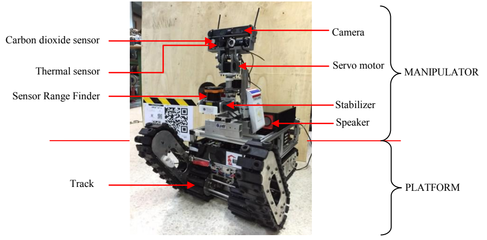
The autonomous robot is divided into two main physical structures, the platform and the manipulator. The platform of the robot has the driving system whereas the second part consists of the manipulator and sensors. The sensors that are attached to the manipulator include: camera, heat sensor, carbon dioxide sensor, and the laser range finder. Special properties of the manipulator are: rotation and extension. The manipulator works with the sensors shown in Figure 2
QR code detection is a task, achieved by the autonomous robot by moving during the mission, therefore the input data is video type and detection is achieved through image processing.
Image processing allows for the detection of QR code throughout the different zones of the arena and is divided into multiple steps. The first step is, to import the video and sampling data into the image processing program. Second, the image goes through pre-image processing such as noise reduction and exposure calibration. The third step is, searching for QR code, therefore the program searches for three main points in the QR code for the purpose of alignment. The final step, the QR code is interpreted into data information that matches the QR code.
5. Robot Locomotion
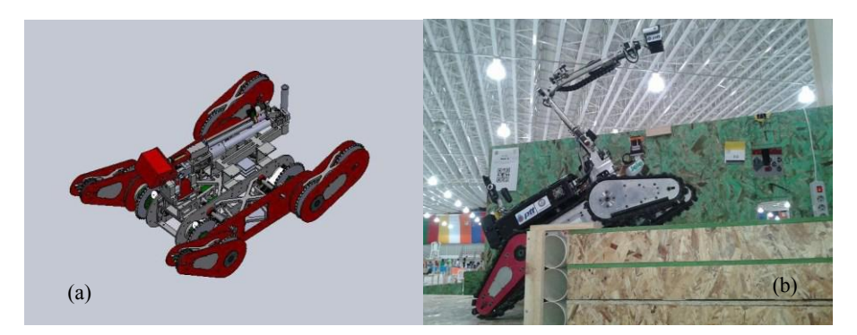
Our robots utilize tracked locomotion systems. Moreover, the tele-operative robots are equipped with four independently controlled flippers to enhance their mobility. The locomotion of these robots is similar to a tank-like system. When the left and right tracks are moving in the same direction, at the same speed, the robot moves either forward or backward. Once the left and right tracks start moving at different speeds the robot will make a turn with respect to the velocity of each track. The maximum speed of the tele-operative robot is almost 0.5 m/sec. On the other hand the robot has a maximum angular velocity of 1.8 rad/sec. To maintain stability during movement up/down a ramp or stairway, the robot has to move at an appropriate speed. Figures 3 (a) and 12 (b) compare the CAD and real image of the robot.
6. Other Mechanisms
In this section, we discuss the six degrees-of-freedom manipulator that can be found on the tele-operative robots. The manipulator is designed to perform in a high vibration environment with strong shock absorption during movement along a rough-terrain. The manipulator is relatively light-weight and strong based on its structure. The folding size of this robot is very compact while the workspace is optimized by using both rotation and prismatic joints. The victim sensing unit is attached to the end-effector of the manipulator, which improves the ability to search and identify the victim's conditions.
7. Possibility for Practical Application to Real Disaster Site
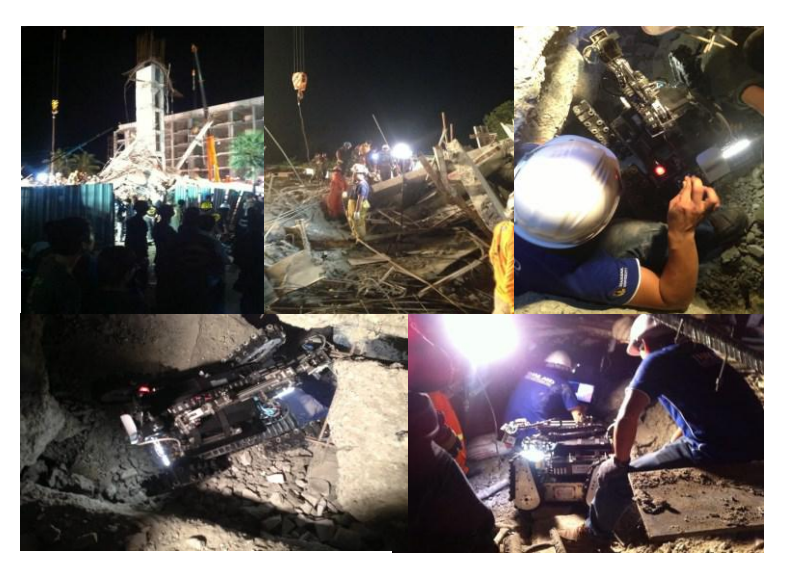
On August 11, 2014, U place condo tale, the six-storey building under construction, collapsed in Pathumthani, THAILAND. There were a number of injured people trapped in the collapsed building. BART LAB Rescue Robotics team was called by the rescue team to join the survey and rescue mission on site. At 01.00 am on August 12, BART LAB Rescue Robotics team arrived and collaborated with Director-General of Department of Disaster Prevention and Mitigation who was in charge of the rescue operation. The top floor of the building was under construction and collapsed into the sandwich structure. Some of the injured were trapped at different depths that were difficult to access from the outside. BART LAB Rescue Robot is designed to operate in rough and complex terrain. However, the height of the robot is 60 cm, which limits the regions the robot is able to gain access to. During the operation the rescue team made the hole to access 3 to 4 floors to locate survivors. The pre-observation was possible to indicate a survivor. BART LAB Rescue Robot was assigned to survey the scene and provide more information on the location of survivors and the structure of the collapse. The robot was remotely operated from the outside station and passed through the 6th floor to the 4th floor. The hole became narrower and lower, additional obstacles included the steel rods that reinforce the concrete structure. Due to these major obstacles, the movement of robot was limited.
However, this is the first mission that BART LAB Rescue Robotics team experienced as part of an on-site operation (Figure 4). The collaboration with the rescue team provided the team with valuable feedback for future improvement and development.
Our ultimate goal is to produce a reliable rescue robot, through research and development, for application in a real disaster site around the world. We strongly believe that our team robots are prepared to perform a rescue task in the real world.
References
- S. Schwertfeger, J. Poppinga, K. Pathak, H. Bülow, N. Vaskevicius, and A. Birk, "Jacobs University," RoboCup Rescue 2009, TDP, Graz, Austria, June 2009.
- T. Nakaya, "NuTech-R," RoboCup Rescue 2009, TDP, Graz, Austria, June 2009
- R. Sheh, A. Milstein, C. Sammut, B. Hengst, G. Dissanayake, and J.V. Miro, "Team Casualty," RoboCup Rescue 2009, TDP, Graz, Austria, June 2009.
- Copyright 2007-2010 (c) Jeff Brown All Rights Reserved
- https://www.hokuyo-aut.jp/02sensor/07scanner/utm_30lx.html
- http://www.optris.com/thermal-imager-pi160
- https://www.sparkfun.com/products/13233