RoboCupRescue 2015 - Robot League Team RRT-Team (Austria)
Raimund Edlinger, Armin Hopf, Walter Rokitansky, Michael Zauner, Roland Giuliano, Iris Grininger, Christoph Diendorfer, Sebastian Mandl, Josef Gürtl, Florian Karer, Michael Schnegg, Christian Krenslehner, Andreas Leitner, Bernd Fuchs, Johannes Hirsch, Kim Windisch, Reinhard Daum, Richard Högl, Thomas Mairhuber
FH OOE Upper Austria Research & Development, Stelzhamerstr. 23, 4600 Wels, Austria; FH OOE – Upper Austria University of Applied Sciences School of Engineering/Environmental/Sciences, Stelzhamerstr. 23, 4600 Wels, Austria
http://rrt.fh-wels.at · http://www-en.fh-ooe.at/research-cooperation/research/research-centers/rd-wels/main-areas-of-research/ · http://www.fh-ooe.at/campus-wels.html
Abstract This paper describes the work of the RRT-Team (RoboRescueTeam) developing and building mobile rescue robots and UAVs. The team consists of research associates and students at the University of Applied Sciences Upper Austria.
This paper includes the preliminary results which are achieved so far about map building, localization and autonomous victim identification. Furthermore the implementation of SLAM and victim detection and a novel mechanism with a dynamic drive system for locomotion is described. Additionally the construction of a modular robotic arm is introduced.
Introduction
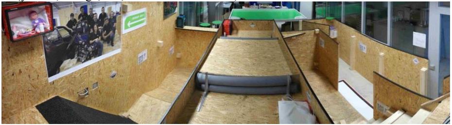
The RRT-Team [1] includes members which already have achieved experience by building autonomous robots for competitions and has been established in late 2007. These robots were able to win competitions such as the Robot-Challenge in Vienna (AUT) the Robot SM in Gothenburg (SWE) and the RoboGames in San Francisco (USA). The robots also started at the Eurobot in La Ferté Bernard (FRA), Rapperswill(CH) and Heidelberg (GER) and the team won the Eurobot 2011 in Astrakhan (Rus).
The RoboCup Rescue League is a competition where autonomous robots navigate through an arena with different level of difficulty such as uneven underground, obstacles and stairs. According to those requirements the development of the robots is very complex and combines multiple disciplines such as mechanical engineering, electrical engineering and programming.
The team participated for the first time in RoboCup Rescue 2009 improving every year. The team won the Best in Class Manipulation competition at the RoboCup German Open 2013 and 2014. At RoboCup 2013 in Eindhoven the 9th place of overall, 2nd place in Best in Class Manipulation and the qualification for the finals in Best in Class Mobility. The RoboCup Rescue League requires the highest demands on the motor and sensory abilities of the robots. The robot is developed specially for the use in the field of security and emergency application. The preliminary aim is to build autonomous and teleoperated robots which are able to drive through an unstructured environment and search for victims. This includes generating a map of the environment and characterizing and locating victims as well as recognizing dangerous situation caused by fire and gas. Building a robot which is supposed to attend the RoboCup Rescue League requires high degree of versatility and experience which makes it difficult to start in this competition from scratch.
The mechanical systems of the robot including the robotic arm are assembled so far. Also the single modules such as the controller board and the peripheral system such as cameras and sensors are tested successfully of our UGV robots, called MARK and RED SCORPION. The main focus concerns the exploration of all different arenas of the competition by generating a two-dimensional map and the detection of victims. The autonomous navigation on rough terrain is a challenging problem for mobile robots because it requires the ability to analyze the environment and make decision which parts can be traversed or need to be bypassed. Due to the developed design, the robots are very fast and agile so it is able to handle all of the arenas.
The major additions compared to the system in the year 2014 are:
- 2D map merging
- New remote control unit
- Electronic parts (IMU and STM32 control board)
- Development of rescue robot "Red Scorpion"
- 3D sensing and mapping
Team Members and Their Contributions
• Raimund Edlinger Team Leader I, Mechanical design, SLAM, Vision
• Michael Zauner Team Leader II, Electronic, Control, Path Planning
• Josef Gürtl Mechanic/Red Scorpion
• Armin Hopf ROS-Software integration, Network
• Christoph Diendorfer Victim Detection/CO2-Sensor, Hazmat Label Detection
• Iris Grininger Software/2D and 3D-Mapping and Path Planning
• Roland Giuliano Software/Robot model
• Sebastian Mandl Software/Victim Detection with RGB and Thermo cam
• Christian Krenslehner Electronic/CAN modul
• Richard Högl Software/Map merging
• Reinhard Daum Software/MoveIT integration
• Johannes Hirsch Mechanic/SLU
• Bernd Fuchs Remote control unit
• Kim Windisch Mechanic/new robot model
• Andreas Leitner Electronic/STM32 control board
• Thomas Mairhuber Electronic/IMU
• Florian Karer Mechanic/3D sensor modul
• Michael Schnegg Software/STM32 framework
• Walter Rokitansky Advisor
2. Communications
For the communication between robot and operator station a Bullet M5 is used which is operating on the 5 GHz band. The wireless communication is used for both, the autonomous modus as well as for the remote control modus.
Table 1: Wireless LAN Communication
| Rescue Robot League | |||
|---|---|---|---|
| RRT-Team FH Wels (AUSTRIA) | |||
| MODIFY TABLE TO NOTE ALL FREQENCIES THAT APPLY TO YOUR TEAM | |||
| Frequency | Channel/Band | Power | Bandwith |
| 5 GHz - 802.11a/n | channel 30-50 | 300mW | 54-300 Mbit/s |
3. Control Method and Human-Robot Interface
[No introductory text for this section]
3.1. Teleoperation
During the remote controlled modus the motion of the robot is controlled by a Microsoft Xbox 360 controller, which is connected to the operator station. Several cameras are mounted on the robot, one at the front and the other one at the rear side of the robot which gives images of the environment. Furthermore a thermo camera and standard cameras are mounted on the top of a robotic arm and provide live stream for the operator.
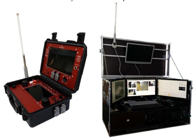
Figure 1 shows RCU 3000 includes four standard 19 inch LCD screens. These screens illustrate the map, the video signals and also the console of the Ubuntu system for teleoperated and autonomous robots. A UPS (Uninterruptible Power Supply) is also included to avoid casualties of the server. The communication takes place via wireless LAN or with a LAN wire.
A new remote control unit was developed (RCU 2000) which provides longer operation runtime and the unit is easy to handle and transport.
3.2. Graphical User Interface
The RRT-Team uses the release ROS Hydro. The tool rqt is a software framework that implements the various GUI tools in the form of plugins. One can run all the existing GUI tools as dockable windows within rqt. The tools can still run in a traditional standalone method, but rqt makes it easier to manage all the various windows on the screen at one moment. The graphical user interface (ROSGUI) is about to be developed which is supposed to display current information of the terrain and environment. This includes the pictures of the thermo camera and the RGB-cameras as well as the data of the CO2 sensor, laser range finder and several other sensors. Additionally the operator gets important information about the robot's battery status and warnings for the obstacle avoidance.
4. Map generation/printing
[No introductory text for this section]
4.1. 2D-Mapping
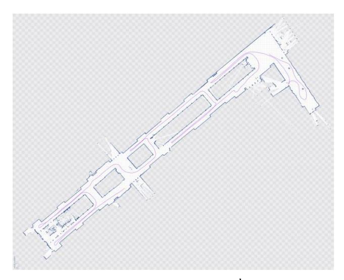
One of the most important tasks at the RoboCupRescue is to explore an unknown terrain and create a map of this terrain. This leads to the common known SLAM (Simultaneous Localization and Mapping) problem. As described in [2] the Robot has to build a map while it is localizing itself. To solve the SLAM problem hector_slam is used by the RRT-Team. Hector_slam consists of several ROS (Robot Operating System) packages. One node of these packages is the hector_mapping node.
Hector_mapping is a SLAM approach that can be used without odometry as well as on platforms that exhibit roll/pitch motion (of the sensor, the platform or both). It leverages the high update rate of modern LIDAR systems like the Hokuyo UTM-30LX and provides 2D pose estimates at scan rate of the sensors (40Hz for the UTM-30LX). While the system does not provide explicit loop closing ability, it is sufficiently accurate for many real world scenarios. The system has successfully been used on Unmanned Ground Robots, Unmanned Surface Vehicles, Handheld Mapping Devices and logged data from quadrotor UAVs [3].
It creates an occupancy grid map using a LIDAR (Light Detecting and Ranging) System. The grid consists of cells which store the information if they are free space, an obstacle or unknown terrain. If the Robot starts exploration the map consists of only unknown terrain cells. If after a few scans the robot detected obstacles it remarks the information in these cells.
4.2. 2D map merging
For the exploration of a large area more robots should be used and each of their maps should be fitted in a global map. Theoretically you can scan an unknown terrain faster and more accurate when you use multiple robots. This is called multivehicle SLAM (Simultaneous localization and mapping). If the grid maps of multiple agents are merged in real time it would be much easier for the path finding algorithm.
4.3. 3D-Mapping
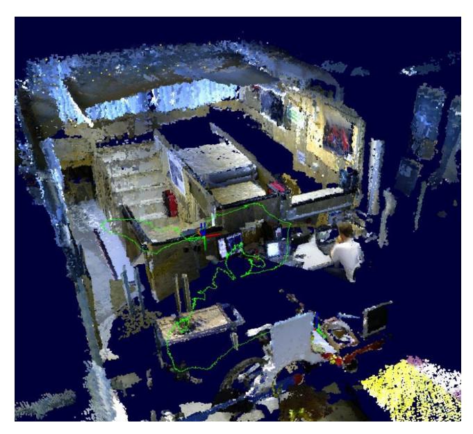
A popular approach to modeling environments in 3D is to use a grid of cubic volumes of equal size (voxels) to discretize the mapped area. During the ROS Summer School in Graz (2012) the researchers have developed 3D-Mapping software. The software stack is based on the OctoMap, which was developed as a probabilistic, flexible and compact 3D Map representation for robotic systems from the University of Freiburg, Department of Computer Science. [13]
5. Sensors for Victim Identification
[No introductory text for this section]
5.1. Vision System
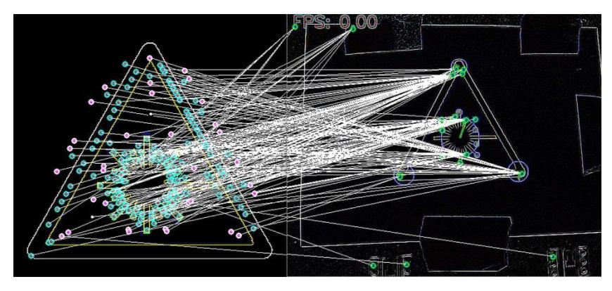
The main task in the Rescue League is to detect victim, draw a map of possible ways into and out of the building and send important information to search and rescue teams. The victims are simulated by dolls which show signs of life as moving, body heat, speaking or least breathing. Closed to the victims hazmat labels and eye charts are placed. So the robot should be able to detect them and send the information to the rescue team. For the detection of these hazmat labels and QR-Codes the robots are using simple USB cameras and a database with different hazmat labels was created. With the use of the OpenCV library and other open-source tools it is possible to try out many different algorithms for computer vision [19].
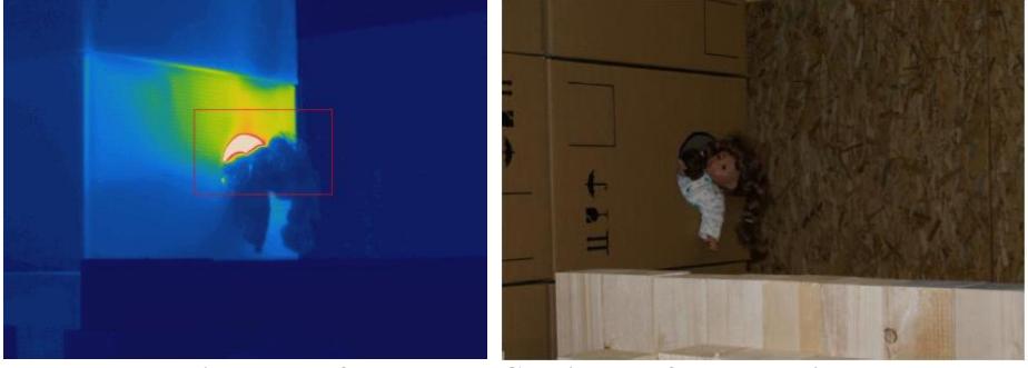
5.2. Thermo Vision System
The core of thermo vision system is the FLIR [8] infrared thermo camera A320 which works in a range of 7.5μm up to 13μm wavelength. The camera uses an uncooled micro bolometer to detect the infrared radiation which is emitted by the objects in the observed area. The A320 camera works at 30 fps which also allows detecting the movement of objects precisely. The data of the sampled information is sent via wireless LAN to the main computer where a program analyses the live stream.
It is planned to implement a smart algorithm which is supposed to detect interesting objects such as victims automatically. Therefore the picture is scanned for conspicuous areas. The objects in the picture should be found using the temperature information. On one hand victims can be classified by a certain body temperature on the other hand dangerous heat sources can be localized. The next step in the development process will be acquiring detailed information about the location of the object and to mark it as an interesting point in the created map. The distance between the robot and the detected object will be calculated using a "depth of focus" algorithm.
For the final solution algorithms are supposed to combine the pictures and their information of the different cameras.
5.3. Other Sensors for Victim Identification
[No introductory text for this section]
Acoustic
For the detection of acoustic signals the microphone 130D20 from PCB Piezotronics [9] is used. It is a pre-polarized condenser microphone with a built in pre amplifier. The range of measurable frequency is from 20 Hz up to 15 kHz which is basically the typical audible range of human. It is built into a very robust steel casing with a BNC connector on the rear side. The incoming signal is first filtered by a digital high pass filter to get rid of noise and then the signal is Fourier-transformed to get the frequency spectrum. The microphone is mounted on the top of the robotic arm close to the cameras.
Gas-Sensor
For detecting carbon dioxide the sensor the CDM4161A CO2 unit from Unitronic [10] is used. This unit uses the TGS 4161 sensor from Figaro. The CO2 sensitive element consists of a solid electrolyte formed between two electrodes, together with a printed heater substrate. By monitoring the change in EMF generated between the two electrodes, it is possible to measure CO2 gas concentration. This highly miniaturized pre-calibrated CO2 sensor unit has low power consumption and no maintenance is required. Furthermore its dependency of humidity is quiet low and its range goes from 350 ppm up to 10.000 ppm. The measuring board CDM4161A is just using a range of 400 ppm to 4000 ppm. As output the sensor unit provides an analog voltage level from 0.4 V to 4 V which is proportional to the carbon dioxide concentration in the air. Then this value is transformed into a ppm-value which denotes one part carbon dioxide per 10^6 parts of air. The sensor is also mounted on the top of the robotic arm.
6. Robot Locomotion
[No introductory text for this section]
6.1. Tracked Vehicle – MARK15
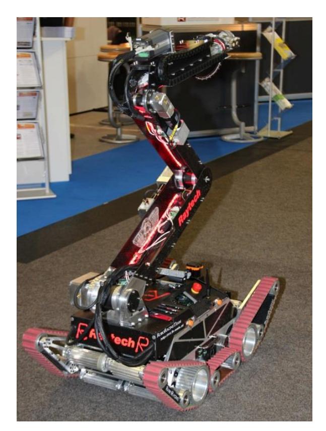
The locomotion of mobile robots in uneven terrain is one of the most difficult demands on the system. On one hand, as an outdoor robot it has to be fast and flexible on the other hand the vehicle has to deal with rough underground such as stones, gravel or stairs. Other important requirements are that the whole system is robust and consists of lightweight construction to reduce the energy consumption.
The MARK15 UGV has four active flippers, where every flipper is driven by two brushless motors, one motor drives the main pulley wheel, the second one is supporting the cantilever. The drive system basically consists of four pulley belts which are driven separately. Additionally the two belts (left and right side) and the middle belts can rotate individually. This is important for tasks like driving over uneven underground and climbing stairs. The body of the vehicle basically consists of an aluminum frame and the gaps, which are for reducing weight, are covered with carbon composite sheets.
6.2. The Scorpions
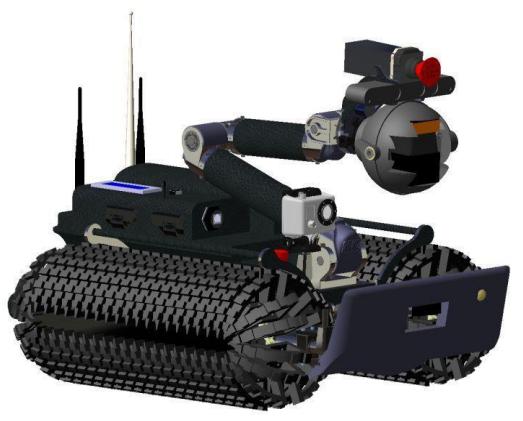
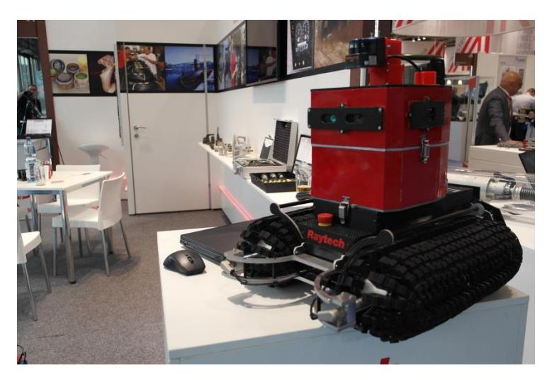
A novel tracked mechanism for sideways motion was developed at Osaka University in September 2011 [16, 17, 18]. The robot can 'turn on a dime', or more correctly, it doesn't need to turn at all. The unique Omni-Ball drive enables it to move in any direction in its plane of operation, and can make those moves almost instantaneously. The Omni-Crawler approach will definitely be a significant benefit in some applications that can be improved by its capabilities, and some applications that were previously impossible.
Both systems will be presented the first time at RoboCup German Open 2013 in Magdeburg (GER) and RoboCup World Championship 2013 in Eindhoven (NED).
7. Field tests
The navigation of the rescue robot in our real disaster environment requires full knowledge of the function of the robot. So the remote controlling system requires a special training and practice for the operator to navigate the robot through the arena. Furthermore a large amount of practicing is necessary to control the 4 chain disk drives. Also the manipulation of the robot arm has to be learned by the operator. The team members are responsible for their contributions and to guarantee an accurate function of the developed algorithms. In the last month competitions are planned between the team members to in order to train operators for the RoboCup Championship. In the next few weeks, the RRT-Team will get a new test arena, where all missions (yellow, orange, red, blue and black arena) can be tested.
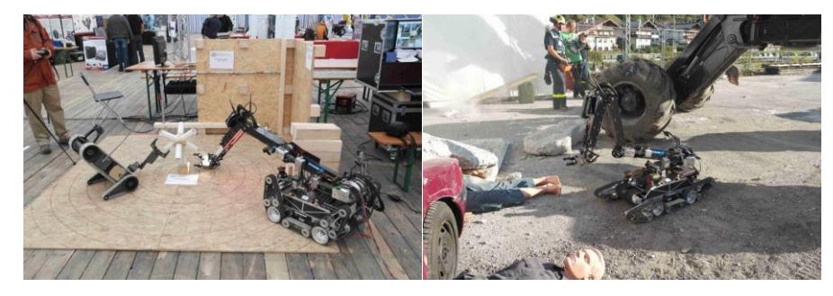
The robotic system is suited to support rescue team for allocating human victims, fire and gas in the case of a real disaster. It is supposed to replace humans in dangerous situations. The motion system, the robotic arm and the new rescue robots, which are mentioned above, allow exploring the operational area and detecting victims and dangerous situations. The team is in contact with fire fighting stations in the City Wels and with the company ROSENBAUER Group which is one of the world's largest manufacturers of fire fighting vehicles and after the competition we have to present the prototype of our rescue robot. With its wide range of municipal fire fighting vehicles we expect to force the development of our robot. The team got practical application at EURATHLON 2013, see following figures.
References
- RRT-Team: Homepage. http://rrt.fh-wels.at Online Resource (February 2013)
- S. Kohlbrecher, J. Meyer, O. von Stryk, and U. Klingauf. A flexible and scalable slam system with full 3d motion estimation. In Proc. IEEE International Symposium on Safety, Security and Rescue Robotics (SSRR), November 2011.
- J. M. Stefan Kohlbrecher, "hector_slam ROS Wiki," 14 December 2011: http://www.ros.org/wiki/hector_slam. Online Resource (Accessed January 2013).
- Stephan Wirth and Johannes Pellenz. Exploration transform: A stable exploring algorithm for robots in rescue environments. Proceedings of the IEEE International Workshop on Safety, Security and Rescue Robotics (SSRR), 2007.
- Hokuyo Automation CO. Ltd.: LRF UBG-04LX-F01 Specifications. http://www.hokuyoaut.jp/02sensor/index.html#scanner – Online Resource (February 2013)
- XSens Technologies B.V.: MTi Development: http://www.xsens.com/en/general/mti Online Resource (January 2013)
- D. Lowe. Distinctive image feature from scale-invariant features, International Journal of Computer Vision (2004)
- FLIR Systems, Inc.: Company http://www.flir.com/map.cfm Online Resource (January 2013)
- CAE Engineering Ltd.: Microphone http://www.produktentwicklung.de/ Online Resource (October 2012)
- Unitronic Ltd.: CO2-Sensor http://www.unitronic.de/ Online Resource (October 2008)
- S. Kohlbrecher, "hector_geotiff ROS Wiki," 03 June 2012. [Online]. Available: http://www.ros.org/wiki/hector_geotiff. [Status 27 January 2013].
- S. Kohlbrecher, K. Petersen, G. Steinbauer, J. Maurer, P. Lepej, S. Uran, R. Ventura, C. Dornhege, A. Hertle, R. Sheh, J. Pellenz, "Community-Driven Development of Standard Software Modules for Search and Rescue Robots", Proc. IEEE International Symposium on Safety, Security and Rescue Robotics (SSRR), November 2012.
- K. M. Wurm, A. Hornung, M. Bennewitz, C. Stachniss, and W. Burgard, "OctoMap: A Probabilistic, Flexible, and Compact 3D Map Representation for Robotic Systems" in Proc. of the ICRA 2010 Workshop on Best Practice in 3D Perception and Modeling for Mobile Manipulation, 2010
- Analog Devices Ltd: http://www.analog.com/en/mems-sensors/mems-inertial-sensors/adis16364/products/product.html Online Resource (Accessed January 2013).
- K. Tadakuma, R. Tadakuma, H. Kinoshita, K. Nagatani, K. Yoshida, M. Udengaard, and K. Iagnemma. Mechanical design of cylindrical track for sideways motion. In Mechatronics and Automation, 2008. ICMA 2008. IEEE International Conference on, pages 161-167. IEEE, 2008.
- K. Tadakuma, R. Tadakuma, K. Nagatani, K. Yoshida, S. Peters, M. Udengaard, and K. Iagnemma. Crawler vehicle with circular cross-section unit to realize sideways motion. In Intelligent Robots and Systems, 2008. IROS 2008. IEEE/RSJ International Conference on, pages 2422-2428. IEEE, 2008.
- K. Tadakuma, R. Tadakuma, K. Nagatani, K. Yoshida, S. Peters, M. Udengaard, and K. Iagnemma. Tracked vehicle with circular cross-section to realize sideways motion. In Robotics and Automation, 2009. ICRA'09. IEEE International Conference on, pages 1603-1604. IEEE, 2009.
- M. Quigley, K. Conley, B. P. Gerkey, J. Faust, T. Foote, J. Leibs, R. Wheeler, and A. Y. Ng. ROS: an open-source Robot Operating System. In ICRA Workshop on Open Source Software, 2009.
- Morel, J. M., & Yu, G. (2009). ASIFT: A new framework for fully affine invariant image comparison. SIAM Journal on Imaging Sciences, 2(2), 438-469.