RoboCup Rescue 2019 Team Description Paper AutonOHM
Philipp Koch, Johannes Vollet, Jasmin Ziegler, Lukas Pichl, Johannes Stark, Marc Hagius, Marco Steinbrink
TH Nuremberg Georg Simon Ohm
www.autonohm.de · [https://robocup-rescue.github.io/team description papers/](https://robocup-rescue.github.io/team description papers/)
Abstract Team AutonOHM has been participating in the RoboCup Rescue League since 2012. The team focuses on autonomous behavior and exploration for rescue robotics. Our strength lies within implementations like SLAM, navigation, or exploration strategies. Approaches for autonomous grasping and automated object detection are under development. Through close contact with the local fire brigade of Nuremberg, the team tries to create solutions that are applicable to disaster scenarios.
Keywords: RoboCup Rescue, Team Description Paper, Autonomous Explorations, SLAM, Manipulation System, RoboCup Sidney 2019
I. INTRODUCTION
AUTONOMHM participated in the RoboCup German Open [1] in 2012 and 2013 with their teleoperated robot Georg. They achieved the second place in 2013, and therefore qualified for the RoboCup World Championship in Eindhoven in 2013, ending up in the 12th spot. In 2014 the team was extended by a second robot named Simon. Deploying this second, more maneuverable robot for teleoperation and Georg for autonomous operation, resulted in an overall second place at the RoboCup German Open in 2014. Furthermore, a second place in the Best in Class Autonomy Challenge was achieved in this year.
In 2015, AutonOHM participated with the same robots. The major focus of the team laid on increasing the level of autonomy, the quality of robot localization and environment mapping as well as cooperative Simultaneous Localization and Mapping (SLAM). These efforts enabled AutonOHM to win the RoboCup German Open in 2015.
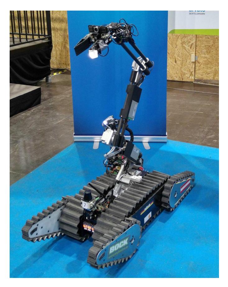
In 2016 the team joined the RoboCup World Championship in Leipzig with a new robot platform (see Fig. 1) capable of driving in rough terrain scenarios [2]. With its new 7-DOF manipulator with three links, the robot enabled AutonOHM to enter the finals. Further developments in the following year concentrated mainly on mechanical improvements of the new platform.
AutonOHM is with the Department of Electrical Engineering, Precision Engineering and Information Technology , Technische Hochschule Nuremberg Georg Simon Ohm, Nuremberg, Germany, e-mail: [email protected] .
At the German Open in Magdeburg in 2017, team AutonOHM achieved the highest score teleoperated in the challenge 'step field' and 'maneuvering center' autonomously and reached the finals. After numerous mechanical defects, an overall 4th place was reached. In the following Best in Class Autonomy challenge, a second place could be achieved.
In 2018, the mechanical design of the robot's drive chain was improved and a new inverse kinematic control for the robot arm was implemented. This improved the control of the robot manipulator drastically and enabled team AutonOHM to score best in most dexterity challenges at RoboCup German Open 2018. The improved drive train allowed the team also to win in hurdles and elevated ramps. With these results, team AutonOHM advanced to the finals and won the first place.
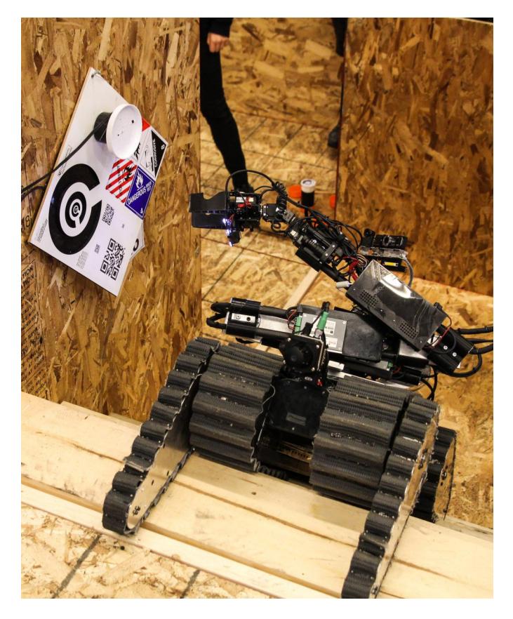
They also participated at the RoboCup World Championship Montreal 2018. In Canada, the inverse kinematic arm control enabled the team to score best in door opening and allowed good results in most dexterity challenges. Further improvements on the drive train (improved track guide) and the robust self developed SLAM approach enabled the team to score well in the mapping challenges. They reached the finals and scored an overall 5th place. Fig. 2 shows the robot on the stairs in the final.
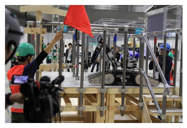
The team was also given the opportunity to compete in the World Robot Summit (WRS) challenge in Tokyo, Japan. This challenge is a preparatory challenge for the World Robot Summit in 2020, which is going to take place on the Fukushima test site. The team achieved good results in mostly all challenges. It was especially successful in autonomous object recognition and mapping and in mobility challenges. The inverse kinematics allowed valuable points in the difficult grasping challenges. AutonOHM reached the finals with these results and reached an overall 3rd place in the Standard Disaster Robotics League. Fig. 3 shows the robot scoring points in the finale challenge.
The challenges of 2018 revealed weaknesses of the robot. Especially the shoring challenges at the World Championship in Montreal, which the robot could not perform, and the grasping challenges at the WRS in Tokyo showed that the manipulator is not strong enough. Moreover, the main drive motors are not fast enough to be competitive. Therefore, a new drive train and a new manipulator will be designed. Another problem the challenges of 2018 revealed is the operator station. The operator had to carry all components during the setup phase which lead to errors. Valuable time was lost. Therefore, the team has decided to build a new operator station with integrated power supply. After improving the mechanical design of the robot, the team will again focus on autonomous software development such as autonomous grasping and exploration.
Since 2014 team AutonOHM uses a self-developed SLAM approach based on the Truncated Signed Distance Function (TSDF) [3], [4], [5]. Over the last years, the team gained expertise in different areas of robotics. This includes 2D and 3D mapping with LiDAR scanners, thermal imaging, sensor fusion, sensor development as well as robot arm manipulation.
A. Improvements over Previous Contributions
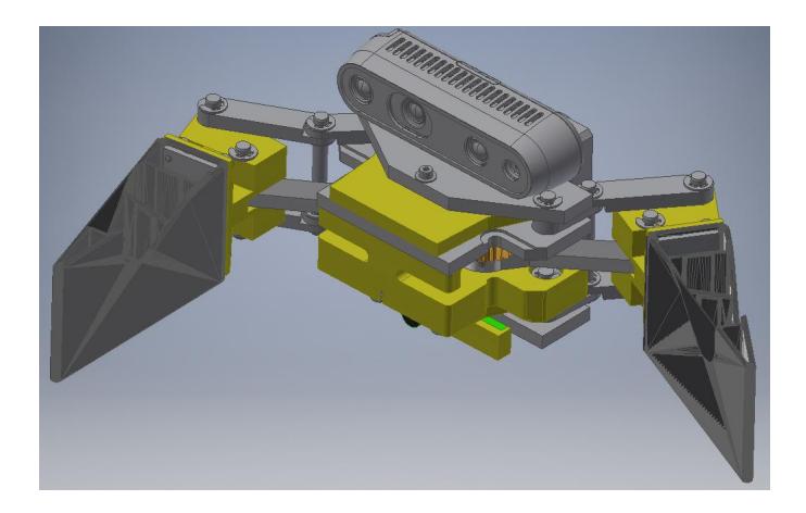
Since the RoboCup world championship in 2018, the following improvements and developments have taken place: a new gripper concept has been developed and implemented. The gripper kinematics is parallelogram shaped so the gripping surfaces stay parallel to each other at all times. This constructive design enables parallel gripping including the backward fold of the gripper jaw after reaching the maximum opening range with the power supply of one single motor.
When both gripper jaws are folded backward, an inspection position with optimal visual field for the gripper camera is achieved. The gripper camera can now be used for inspection purposes withouth view limiting factors. The design is depicted in fig. 4. This new gripper design will solve one of the major problems the robot faced during the challenges in 2018, the strength of the manipulator. With this new gripper design, Schroedi will be able to compete in the shoring tasks as well.
The manipulator now contains a SeekThermal infrared camera. The limited payload capacity made it impossible to carry an Optris infrared camera. The light and small SeekThermal cameras enable Schroedi to search for heat signatures in difficult to reach regions. The SeekThermal devices are designed to be used with smartphones and are therefore comparably small in design and weight.
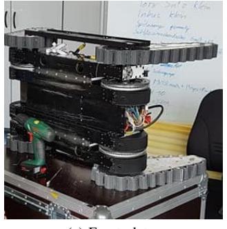
During the German Open 2018 in Magdeburg, the robot suffered a motor failure after it lost one of its tracks in the elvevated ramps challenge. Losing the tracks was a common error of the robot and was therefore subject of a mechanical redesign. A first prototype design was finished just before the World Championship in Canada and printed in a 3D printer. As the motor was damaged through over temperature, an active cooling system is included into the bottom plate. Fig. 5 shows how the guide works. The track can no longer wobble as the plastic guide plates keep it in place.
Another problem which occurred during the challenges of 2018 is Schroedi's speed. In order to prevent motor failure, the max RPM have been reduced. The friction loss of the track guide also added to the power and speed problems. In order to deal with this problem, new Maxon DC motors RE 40, each with a power of 150 W, will be build into newly designed gearboxes.
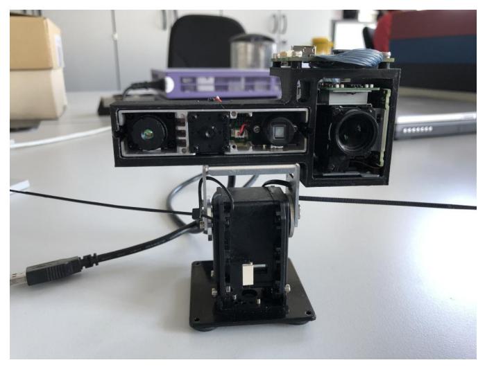
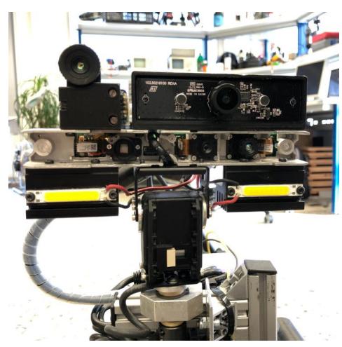
Inspired by the technology of a Telemax robot the team competed against at the WRS, Schroedi's sensor-head is being redesigned. A Tamron MP1110M-VC zoom camera is added to help the operator in inspection tasks. This camera is capable of 10x optical and 16x digital zoom. Additionally, an Orbbec Astra RGB-D camera replaces the Asus Xtion sensor which reduces the width of the sensor head drastically. This will ease challenges like the Jungle Gym where the sensor head used to collide with obstacles. The heavy Optris infrared camera is replaced with a SeekThermal device. Additionally, the webcam which was used for teleoperation is replaced by a Basler Dart daA1600-60uc industry camera. With its global shutter it is less affected by vibrations. A wide angle lens helps the operator to get a better overview. Fig 6 illustrates the current work. The image shows the Orbbec Astra RGB-D camera and the attached Tamron zoom camera. The thermal imager and Basler RGB camera will be added to the new design.
During the challenges in 2018, a new Graphical User Interface was developed to deal with the increased complexity of the the robot. A main problem was that the operator had only one comparably small screen of a laptop and in some challenges an additional screen. Multiple windows to display important information would have reduced the size of the main driving or manipulating feed.
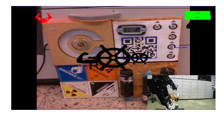
To deal with this problem, a custom Qt based Head Up Display (HUD) was developed. Relevant information like the battery capacity or the current angles of the flippers are displayed into the main camera feed in order to show the most amount of information on the one hand but display the driver camera feed as big as possible on the other one. The robot and its flippers are displayed as transparent grid model from a third person style view and during manipulation mode, the driver camera is displayed as smaller picture in picture to help the operator during difficult manipulation tasks.
An additional problem is the game pad. Team AutonOHM is using a Play Station (PS) 3 game pad. With its two analog sticks and two analog buttons, the robot controls (flippers, tracks, sensor head angle) or the manipulator control (tool center point control, end effector axis) require most of the buttons and axes. Therefore, the GUI defines operation modes which are set by a rolling menu displayed into the HUD. The operator can switch between forward and backward driving mode or manipulator mode or use shortcuts for predefined flipper positions. In backward driving mode all controls are switched and the head is turned automatically. This mode has been added in order to save time in RoboCup challenges. Instead of turning around, the operator can simply drive backwards.
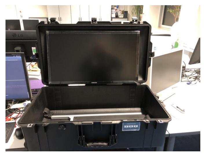
The RoboCup and WRS rules define a strict, restricted setup time. In 2018, the AutonOHM operator had to carry its operator station (laptop, WiFi router, additional display, Uninterrupted Power Supply (UPS)) to the start box which resulted in problems. For instance, in the final of the WRS, the router power cable was pulled out during setup which caused a delay of nearly 3 minutes as the network had to be restarted. In order to deal with this problem, a new operator station is being developed. It is based on a Peli Air case which can be checked in as luggage for air travel. The case will contain a 28inch display, the WiFi router with UPS and antennas and connectors for the operator laptop. Fig. 8 depicts the new operator station.
In order to reduce the amount of USB connections, a second computing unit Intel NUC7i7DNKE was added. This unit is mounted on the sensor head and is mainly used for the fusion of the gripper and sensor head sensor data.
II. SYSTEM DESCRIPTION
The software architecture of our robot is based on the Robot Operating System (ROS) [7]. The chassis of Schroedi has been developed in cooperation with the RoboCup Rescue Robot Team of the Carinthia University of Applied Sciences Villach [8]. With its chain wheel drive and four flippers, it is able to handle complex obstacles like stairs and step-fields. The robot arm is capable of inspection and manipulation tasks like opening doors. The system will be remote controlled and additionally in most of the maneuvering challenges autonomously as well.
A. Hardware
The robot's hardware is designed for robust long term missions in disaster areas and will be described in this section.
a) Leveling Platform
The leveling platform consists of two servo drives which are able to align the laser scanning plane horizontal with two degrees of freedom (Figure 9d). The orientation of the chassis is measured with an Inertial Measurement Unit (IMU), which is mounted on the chassis. An Arduino board receives the data from the IMU and calculates the required angles of the axes to keep the scanning plane aligned horizontally. Both servo drives are directly connected to the Arduino board. The leveling platform is an independent system on the robot.
b) Sensor Head
The sensor head is used to orientate different sensors with a single platform (Figure 9a). Two servo drives are used to pan and tilt the sensor head. It is equipped with an infrared camera, an RGB camera with auto focus and an RGB-D camera. All sensors are calibrated to each other by an extrinsic and intrinsic matrix. The sensor head is mainly used for visual inspection. Victims can be located quickly using different visual sensors. Figure 9a illustrates the sensor head with its sensors. During the challenges of 2018, the Optris infrared camera has already been exchanged with a SeekThermal device. The team also added LED lights below to illuminate dark areas.
c) Motor Controller
Team AutonOHM developed a custom motor controller: The robot is equipped with four Brush Less DC (BLDC) motors for the main drive and four BLDC motors for the flippers (see Figure 9b). The eight controllers, based on Maxon EC amplifier DEC modules 50/5, are integrated into a compact motor driver stack. The stack consists of four NXP KV31 based slave boards, each of which controls two motors. The Atmel Atmega328 based master board, which also includes the required power supplies and galvanic isolation, connects the stack via USB to the ROS-System.
d) Manipulator
Sometimes victims are not directly reachable for the mobile robot, e.g. a victim is located behind an obstacle. For such cases, the mobile platform needs an inspection arm to improve victim localization abilities. Schroedi is equipped with a 7-DOF robot arm. To achieve higher compactness of the manipulator without reducing the operation range, it has three links instead of two compared to most existing robot arm configurations. (see Figure 9c).
The Tool Center Point (TCP) holds an RGB-D camera, audio sensors, a CO2 sensor and a gripper (see Figure 9e). Due to its 7 degrees of freedom the robot arm is able to fulfill complex inspection and manipulation tasks. The maximum payload is limited to 0.5 kg when it is fully extended. The robot arm can reach objects within a distance of 1.5 m. The manipulator can be controlled teleoperated with a game pad controller or autonomously. In order to search for life signs, it is equipped with a microphone and a CO2 sensor.
During the challenges of 2018, the SeekThermal infrared cameras where added to the system. Their small design and low weight made it possible to use such a device on the gripper. A speaker enables the operator to talk to a potential victim. The current design is depicted in Fig. 9e. The new gripper design, which is currently under development, enables parallel gripping including a backward fold of both gripper jaws for an optimal visual field for the gripper camera.
e) Drive train
After a mechanical breakdown during the RoboCup German Open Finals in 2017, the mechanical parts of the drive train had to be improved. The shaft-hub connections were optimized from a form-fit connection with a feather key to a force-fit connection using a clamping set. The advantage of the new concept (see Figure 9f) is higher stability even if alternating and bunting loads occur. The drive train is designed to overcome slopes of $45^{\circ}$ as well as $15^{\circ}$ slopes with an additional load of $50,\mathrm{kg}$.
B. Software
The following section demonstrates the algorithms and software of AutonOHM for the RoboCup Rescue League.
a) Low Level Control: The low-level control of Schroedi is responsible for the basic control of actors and the access to the sensor signals. The commonly known robot middle-ware Robot Operating System (ROS) is responsible for the communication [7]. The software is structured in nodes, each containing a single executable. The exchange of information between these ROS nodes is realized by ROS data types, e.g., messages, services or actions, via TCP/IP. On the startup of the robot, different checks are applied to the sensors and actors. If tests fail e.g., a sensor cannot provide data in sufficient cycle time, or an actor does not provide feedback, the startup aborts and the operator of the robot is informed.
b) Localization and Mapping: A self developed Simultaneous Localization and Mapping (SLAM) approach ohm_tsd_slam is used to generate a map of unknown environment with a 2D laser scanner. Information like the location of victims or points of interest is stored according to this map. A major feature of ohm_tsd_slam is that multiple robots can create a map together. Additionally, robust localization is guaranteed by the use of a Random Sample and Consensus (RANSAC) approach [9].
c) Victim Detection: Vital signs are detected with the help of different sensors. A sensor head is used to orientate the sensors without moving the whole robot. The sensor head uses video-, thermal- and RGB-D cameras for virtual perception. A CO2 sensor is mounted on the manipultor to detect breathing. An approach for the automatic detection of heated objects was developed to allow a faster sensor check as well as to improve the object detection during exploration missions [10]. Parts of the developed software are free to use and open access via [11].
d) Navigation: For autonomous navigation, the ROS package RONA (Source: https://github.com/schmiddey/rona) is used. It contains path planning based on the A* algorithm and is suitable for single and multi-robot path planning [12]. Additionally, the package contains basic implementations for path control. Also, it includes an implementation for frontier-based exploration. In contrast to the common ROS navigation stack, RONA is lightweight and needs less parametrization.
e) Point of Interest Search: For a real disaster scenario, the generated map is searched for wall segments. At first, points which change their state from free cells to occupied cells are extracted. In this set of points the wall finder searches for straight lines using RANSAC [9] algorithm. The Occupancy Grid Map is a 2D map, so straight lines are interpreted as walls. The wall finder locates both sides of a wall. Based on the extracted walls, target poses (points of interest) are computed and inspected by the robot. This improves the robustness of finding potential victims.
f) Exploration: Schroedi can explore unknown environments based on laser scan sensor data. The sensor data is processed by the Frontier Exploration approach, presented by Yamauchi [13]. This algorithm uses the occupancy grid map to find regions which the autonomous robot has not seen before. The frontier algorithm searches for frontiers between free cells and unknown cells. These frontiers must fulfill some conditions, e.g., the frontier must be as wide as the robot. Additionally, the frontiers are sorted and prioritized based on their size and the navigation distance to the robot. Although the exploration does not rely on user interaction, a user can define areas in the map, which are prioritized higher, to enhance the performance in exploration.
g) Arm control: The complexity to solve the inverse kinematic problem rises with the number of joints, and with their configuration. The manipulator of Schroedi shown in Figure 9c has seven joints. Joints 2-4 are parallel which results in redundancy and joints 5-7 build a spherical wrist. To solve the inverse kinematics problem there is a combined analytical and iterative solution implemented. The orientation problem of the end-effector is solved analytically due to the spherical wrist. The positioning problem of joints 1-4 is solved with an optimization algorithm based on [14]. The solution is stable near singularities and considers joint limits. The end-effector is controlled manually with a gamepad controller. To solve tasks autonomously the arm uses the input data of two 3D-cameras (see Figure 11a and 11b).
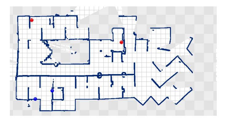
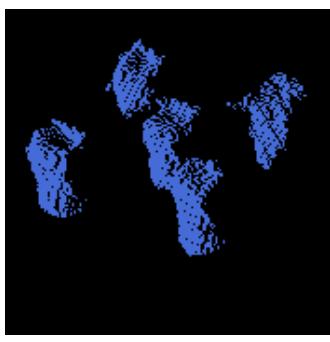
TABLE I. NETWORK COMMUNICATION FOR ROBOTS AND OPERATORS.
| Frequency | Band | Power(mW) |
|---|---|---|
| 5.0 GHz - 802.11a | 157 | < 125 |
C. Communication
For network communication, the frequency of 5 GHz in channel 157 has been chosen. Table I shows all used frequencies and their transmission power.
D. Human-Robot Interface
For mobility and maneuvering challenges the robot is controlled by a gamepad. The controlling is similar to computer games and allows easy adaptation. Important information is displayed in the main driving or manipulation camera feed. The operator can choose between forward and backward driving mode or manipulation mode. The game pad commands are mapped according to the chosen mode and the main camera feed is set to either driver camera or manipulator camera. The manipulator camera is mounted on the gripper. In manipulation mode, a small camera image displays the driver camera to help the operator in difficult manipulation challenges.
To set up the robot for a mission, several measures have to be accomplished, for instance, powering up the drives and enable panning of the laser scanner. A checklist and basic training for team members and contributors minimize errors during the start-up phase.
III. APPLICATION
(none)
A. Set-up and Break-Down
Due to pressure of time in competition, setup and handling of the robots and the operator station needs to be efficient. The network is powered by an uninterruptible power supply and can operate for several hours without external powering. Router, antenna and power supply are mounted to one unit for easy carrying. The operator uses a laptop computer to communicate over the network with the robot. The robot is ready to run within a few minutes. Because of the robot's weight of more than 70 kilograms and the uninterruptible power supply, the set-up needs to be done by at least two persons.
B. Mission Strategy
In the classic rescue competition, Team AutonOHM focused on multi-robot systems: One robot is not enough to fulfill the various tasks in RoboCup Rescue as well as in a real disaster scenario. Therefore several robots should help task forces to search for victims. For RoboCup Rescue one robot was controled teleoperated while a second robot performed autonomous exploration and victim detection. With this mission strategy, the amount of possible points per mission was doubled.
Since the competition changed in 2016, the team focuses on the evolution of one robot, capable of coping with any terrain or challenge in RoboCup, WRS or at a real rescue scenario. In the setup phase, the team tries to score as many multipliers as possible. using the carried sensors and its manipulator. The robot's software enables it to perform in some challenges autonomously, for instance MAN1, MAN2, MAN4 or the exploration and mapping challenges.
C. Experiments
Team AutonOHM tested different sensors for different scenarios: Optical sensors could fail in an environment containing smoke or dust. Besides optical sensors, ultra sonic range finders and RADAR sensors are tested to guarantee perception in such an environment. This is why the fusion of different sensors is necessary to provide enough robustness [6]. During a research project with the Deutsche Bahn (German Railway), where a shunting locomotive was automated, experiences were made [10]. Since 2014 team AutonOHM collaborates with the local fire brigade of Nuremberg, testing sensors suitable for zero sight areas due to smoke.
D. Application in the Field
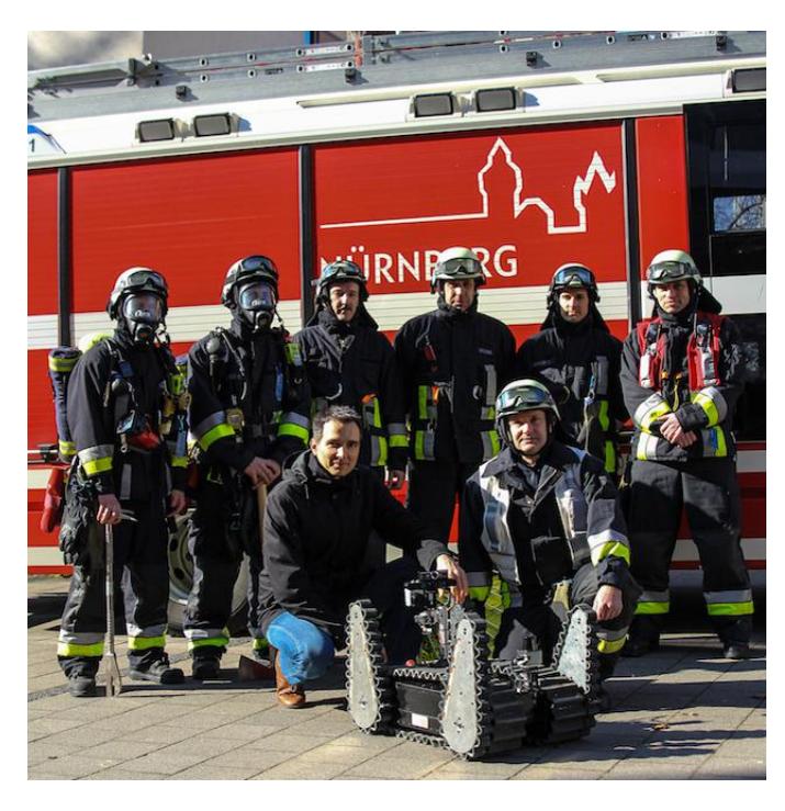
Since 2013 team AutonOHM has been cooperating with the fire brigade of Dettelbach, Germany as well as in Nuremberg, Germany in order to discover the requirements for humanrobot collaboration. (see Figure 12) The acceptability of the fire-fighter depends on their age and their experience with computer technology. The robot should increase its durability and battery life more to perform well in a real disaster scenario. Also, signal shielding from a concrete dam or steel-girder constructions can cause errors and should be concerned. In August 2016 a workshop took place in cooperation with the fire brigade No. 3 in Nuremberg. Different techniques using different cameras and laser scan mapping were demonstrated. The laser scan maps allow the incident commander to direct his men for finding victims in time. This will save lives in the future [17].
IV. CONCLUSION
The mobile robot Schroedi is starting in his fourth competition year. The drive train was optimized heavily after the breakdowns of the first two years. After the German Open 2018 in Magdeburg, the robot suffered a motor failure caused by overheating as it lost one of the tracks in the elevated ramps challenge. In order to deal with the heat problem of the motor and the track loss, a new track guide system was designed which prevented the loss of the tracks successfully wherefore the robot could cope with any mobility challenge at the RoboCup World Championship or at WRS.
With the drive train finally stable, only the speed issue remains which will be fixed with the new motors, wherefore the focus of the team in 2019 will be autonomous behaviour in mobility and dexterity challenges. An autonomous grasping approach is currently being developed and will be tested during the challenges of 2019. Autonomous traversability mapping, exploration and 3D path planning are being developed in the team as well.
APPENDIX A TEAM MEMBERS AND THEIR CONTRIBUTIONS
Team AutonOHM consists of several students and research assistants of the TH Nuremberg Georg Simon Ohm. The following list is in alphabetic order:
TABLE II. SCHROEDI
| Attribute | Value |
|---|---|
| Name | Schroedi |
| Locomotion | tracked |
| System Weight | 70kg |
| Weight including transportation case | 85kg |
| Transportation size | 0.8 x 0.5 x 0.5 m |
| Typical operation size | 1.2 x 0.5 x 0.5 m |
| Unpack and assembly time | 15 min |
| Startup time (off to full operation) | 10 min |
| Power consumption (idle/ typical/ max) | 60 / 200 / 800 W |
| Battery endurance (idle/ normal/ heavy load) | 240 / 120 / 60 min |
| Maximum speed (flat/ outdoor/ rubble pile) | 1 / 1 / - m/s |
| Payload (typical, maximum) | 3/ 10 kg |
| Arm: maximum operation height | 155 cm |
| Arm: payload at full extend | 0.5kg |
| Support: set of bat. chargers total weight | 2.5kg |
| Support: set of bat. chargers power | 1,200W (100-240V AC) |
| Support: Charge time batteries (80%/ 100%) | 90 / 120 min |
| Support: Additional set of batteries weight | 2kg |
| Cost | EUR 26,000 |
TABLE III. OPERATOR STATION
| Attribute | Value |
|---|---|
| Name | Operator Station |
| System Weight | 3.2kg |
| Weight including transportation case | 4.5kg |
| Transportation size | 0.4 x 0.4 x 0.2 m |
| Typical operation size | 0.4 x 0.4 x 0.4 m |
| Unpack and assembly time | 1 min |
| Startup time (off to full operation) | 1 min |
| Power consumption (idle/ typical/ max) | 60 / 80 / 90 W |
| Battery endurance (idle/ normal/ heavy load) | 5 / 3 / 2 h |
| Cost | EUR 2,800 |
TABLE IV. HARDWARE COMPONENTS LIST
| Part | Brand & Model | Unit Price | Num. |
|---|---|---|---|
| Drive Motors | Maxon EC-4pole 30 200 W | EUR 645 | 4 |
| Robotis Dynamixel MX 28T | EUR 175 | 4 | |
| Motor Encoder | Maxon MR 500 Ticks | EUR 92 | 4 |
| Motor Gear | Maxon GP 42 C | EUR 234 | 4 |
| Motor Controller | Internal Development | EUR 200 | 1 |
| Flipper Motors | Maxon EC max 40 70 W | EUR 490 | 4 |
| Flipper Motor Encoder | Maxon MR 512 Ticks | EUR 92 | 4 |
| Flipper Motor Gear | Maxon GP 42 C | EUR 248 | 4 |
| Motor Drivers | Maxon DEC 50/5 | EUR 57 | 8 |
| USB2Dynamixel | EUR 45 | 1 | |
| Power Supply | Internal Development | EUR 35 | 2 |
| M3-ATX-HV 6-34V DC/DC (95 W) | EUR 57 | 2 | |
| Internal Development DCDC-NUC | EUR 50 | 1 | |
| EUR 59 | 1 | ||
| Batteries | mylipo HV-Lipo 4100mAh 22,2V 6S 35C/70C | EUR 73 | 8 |
| Servo Motors Chassis | Robotis Dynamixel MX28-T | EUR 175 | 4 |
| Servo Motor Controller | USB2AX | EUR 34 | 1 |
| Additional Computing Unit Intel NUC7i7DNKE | EUR 600 | 1 | |
| Micro Controller | Arduino Micro | EUR 18 | 1 |
| WiFi Router | D Link AC3150 MU MIMO | EUR 176 | 1 |
| WiFi Bridge | Netgear N900 | EUR 60 | 1 |
| IMU | XSense Mti-10 | EUR 1,100 | 1 |
| Bosch BNO055 | EUR 30 | 1 | |
| Cameras | Orbbec Astra Mini | EUR 180 | 1 |
| Basler Dart daA1600-60uc | EUR 324 | 1 | |
| Intel Realsense d435 | EUR 180 | 1 | |
| Shenzhen Arashi Vision Company Limited Insta360 Air | EUR 75 | 1 | |
| Tamron MP1110M-VC | EUR 600 | 1 | |
| Infrared Camera | Seek Thermal CompactPro FF | EUR 500 | 1 |
| Seek Thermal Compact | EUR 250 | 1 | |
| LRF | SICK TIM-571 | EUR 2500 | 1 |
| Microphone | Rode VMMICRO VideoMicro | EUR 40 | 1 |
| CO2 Sensor | DFRobot SEN0220 | EUR 70 | 1 |
| 7-axis Robot Arm | Harmonic Drive(HD) CHA17A-100-E | EUR 2,400 | 1 |
| HD FHA-14C-100E | EUR 1,600 | 2 | |
| HD FHA-11C-100E | EUR 1,500 | 1 | |
| Robotis Dynamixel XH430-V350-R | EUR 230 | 4 | |
| Motor Drivers | Elmo MC Gold DC Whistle | EUR 600 | 4 |
| Servo Motor Drivers | USB2AX | EUR 34 | 1 |
| Power Station | OpenUPS, Multistar High Capacity 4S 10000mAh | EUR 115 | 1 |
| Battery Charger | Voltcraft V-Charge 200 Duo | EUR 80 | 1 |
| Rugged Operator Laptop | Lenovo Thinkpad P52 | EUR 3,500 | 1 |
TABLE V. SOFTWARE LIST
| Name | Version | License | Usage |
|---|---|---|---|
| Ubuntu | 16.04 | open | Operation System |
| ROS [7] | kinetic | BSD | Middle Ware |
| PCL [15] | 1.7 | BSD | ICP |
| OpenCV [18], [19] | 2.4.8 | BSD | Haar: Victim detection |
| OpenCV [16] | 2.4.8 | BSD | LBP: Hazmat detection |
| Qt4 | 4.8 | GPL | GUI |
| ohm tsd slam | kinetic | Multi-Robot SLAM | |
| optris drivers | kinetic | BSD | Thermal Imager |
| MoveIt! | kinetic | BSD | Robot arm control |
| TRAC-IK | v1.4.0 | BSD | Inverse kinematic |
APPENDIX B LISTS
(none)
References
[1] A. Jacoff, R. Sheh, A.-M. Virts, T. Kimura, J. Pellenz, S. Schwertfeger, and J. Suthakorn, "Using competitions to advance the development of standard test methods for response robots," in Proceedings of the Workshop on Performance Metrics for Intelligent Systems. ACM, 2012, pp. 182–189.
[2] C. Pfitzner, M. Fees, M. Kuhn, M. Schmidpeter, P. Koch, and S. May, "Robocup rescue 2016 team description paper autonohm," 2016.
[3] S. May, P. Koch, R. Koch, C. Merkl, C. Pfitzner, and A. Nuchter, "A generalized 2D and 3D multi-sensor data integration approach based on signed distance functions for multi-modal robotic mapping," in 19th International Workshop on Vision, Modeling and Visualization, VMV 2014, 2014.
[4] C. Pfitzner, W. Antal, P. Hess, S. May, C. Merkl, P. Koch, R. Koch, and M. Wagner, "3d multi-sensor data fusion for object localization in industrial applications," in ISR/Robotik 2014; 41st International Symposium on Robotics; Proceedings of. VDE, 2014, pp. 1–6.
[5] P. Koch, S. May, M. Schmidpeter, M. Kuhn, C. Pfitzner, C. Merkl, R. Koch, M. Fees, J. Martin, and A. Nuchter, "Multi-robot localization and mapping based on signed distance functions," in Proceedings - 2015 IEEE International Conference on Autonomous Robot Systems and Competitions, ICARSC 2015, 2015.
[6] J. Gleichauf, C. Pfitzner, and S. May, "Sensor fusion of a 2D laser scanner and a thermal camera," in ICINCO 2017 - Proceedings of the 14th International Conference on Informatics in Control, Automation and Robotics, vol. 1, 2017.
[7] M. Quigley, K. Conley, B. P. Gerkey, J. Faust, T. Foote, J. Leibs, R. Wheeler, and A. Y. Ng, "ROS: an open-source Robot Operating System," in ICRA Workshop on Open Source Software, 2009.
[8] P. Hofer, M. Sereinig, S. Quendler, and W. Werth, "Robocup rescue 2016 team description paper cuas rrr," 2016.
[9] M. A. Fischler and R. C. Bolles, "Random sample consensus: A paradigm for model fitting with applications to image analysis and automated cartography," Commun. ACM, vol. 24, no. 6, pp. 381–395, June 1981. [Online]. Available: http://doi.acm.org/10.1145/358669.358692
[10] J. Gleichauf and S. May, "Obstacle avoidance system for an autonomous shunting locomotive," Applied Research Conference, 2017.
[11] GitHub, "ohm rrl perception," https://github.com/autonohm/ohm_rrl_perception, 2016.
[12] P. E. Hart, N. J. Nilsson, and B. Raphael, "A formal basis for the heuristic determination of minimum cost paths," IEEE Transactions on Systems Science and Cybernetics, vol. SSC-4(2), pp. 100–107, 1968.
[13] B. Yamauchi, "A frontier-based approach for autonomous exploration," in Computational Intelligence in Robotics and Automation, 1997. CIRA'97., Proceedings., 1997 IEEE International Symposium on, Jul 1997, pp. 146–151.
[14] L. C. T. Wang and C. C. Chen, "A combined optimization method for solving the inverse kinematics problems of mechanical manipulators," IEEE Transactions on Robotics and Automation, vol. 7, no. 4, pp. 489–499, aug 1991. [Online]. Available: http://dx.doi.org/10.1109/70.86079
[15] R. B. Rusu and S. Cousins, "3D is here: Point Cloud Library (PCL)," in IEEE International Conference on Robotics and Automation (ICRA), Shanghai, China, May 9-13 2011.
[16] A. Bradski, Learning OpenCV, 1st ed. O'Reilly Media, 2008.
[17] T. Tjiang, "Roboter Schroedi soll Leben retten," https://www.mittelbayerische.de/region/nuernberg-nachrichten/roboter-schroedi-soll-leben-retten-21503-art1422050.html, accessed: 2018-03-08.
[18] P. Viola and M. Jones, "Rapid object detection using a boosted cascade of simple features," in Computer Vision and Pattern Recognition, 2001. CVPR 2001. Proceedings of the 2001 IEEE Computer Society Conference on, vol. 1, 2001, pp. I–511–I–518 vol.1.
[19] R. Lienhart and J. Maydt, "An extended set of haar-like features for rapid object detection," in Image Processing. 2002. Proceedings. 2002 International Conference on, vol. 1, 2002, pp. I–900–I–903 vol.1.