RoboCup Rescue 2019 Team Description Paper Club Capra
Alexandre Francoeur, Ludovic Vanasse, Marc-Olivier Belisle
École de technologie supérieure
https://clubcapra.com · https://robocup-rescue.github.io/team_description_papers/
Abstract RoboCup Rescue is a division of RoboCup competition which focus on the use of robot in search and rescue applications. This robot was the first prototype of our club built for RoboCup Rescue, although we still tried to innovate in some way. One of the main features in our design is the suspension system of our tracks. We also tried to innovate on the software side of the robot with Landolt C detection and CANBus control for the motors.
Index Terms
RoboCup Rescue, Team Description Paper, Search and Rescue Robots, Robotics in Hazardous Fields.
I. Introduction
RoboCup competition which focus on the use of robot in search and rescue applications. This robot was the first prototype our student club built for RoboCup Rescue. The design of the robot was a two part focus, we wanted to build something that the next generation of student in our club could build upon and also innovate to standout from the more conventional design from the previous years. One of the main features in our design is the suspension system of our tracks. The suspension system helps the robot navigate on rough terrains. The suspension add clearance underneath the robot, which enable it to navigate more freely in cluttered environment. Apart from the track system, we decided to power our robot with power tool batteries, this decision has a lot of advantages. First, the batteries are made for heavy duties applications, so they are able to deliver all the current we need for the drive train and control electronics housed inside the robot. There's also the fact that they are easily exchangeable, have high fidelity and great autonomy. The robot is driven by 4 motors which are all controlled through a CAN Bus network. With this design we can control all the drive through one pair of twisted cables connected to our computer inside the robot. CAN Bus allows us to communicate to the drives controlling the motors and to configure different behavior, this gives us more flexibility and control on how the motors operate. One last feature about the robot, is the Landolt C software for the thermal image resolution. We were able to code a detection algorithm for the concentric Landolt C. Finally, there's many more features that we implemented in our prototype and we are excited about testing them to their limits.
II. System Description
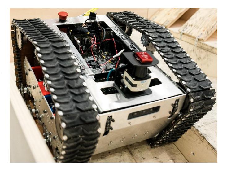
The software architecture of our robot is based on the Robot Operating System (ROS). We created a node for each physical and logical component and ROS helped us connect everything together. Also the robot has a simple user interface for easy operation. Our electrical design is running on a nominal 20V direct current based on power tool batteries. This design can handle complex and long operation period easily. The mounted arm enable manipulation task and its reach ease the access of high precision target position. The suspension system stabilize the trajectory of the robot, allows greater speed over rough terrains and reduce frame contact on the ground.
A. Hardware
The robots hardware is designed for long and complex tasks and will be described in this section
Locomotive: The robot has of 4 motors, 2 in the front and 2 in the back. Each side has 2 chains drive by 4 gearing. The motors drives are connected to the on-board computer by the CAN Bus network and powered through our power distribution system to protect the hardware from a power surge. Power is provided by 6 power tool batteries.
Basket: The Jetson TX2, the on-board computer, is inside a metal basket and can be easily removed for test and repair. Along with the on-board computer, there are two PCB's, one regulating the power for the on-board computer and the other interfacing our computer to the CAN Bus network. For communication purpose a router is situated on top of the on-board computer and fixed in the basket.
Manipulation: The robotic arm is mounted above the basket and supported with 4 bolts. It has 6 degrees of freedom and have a hand that can pinch, lift, poke and move objects. On its wrist, multiple sensors like a thermal camera, a RBG camera and microphone are used to detect victim in hard to reach locations.
Vision: The main vision of the robot is the front camera. This camera is RGB and can record the depth field of the environment. There is another camera in the rear which help navigate backward and see potential obstacle. To further the robot vision, there is a LiDAR on top of the frame to help localize and mapping the surroundings.
Sensors: The robot has an IMU which help the robot by measuring the gravitational force and the acceleration for multiple applications like localization and mapping. A speaker is installed to communicate instructions or speak with a found victim. There is also a CO2 sensor that can detect human presence in the surroundings.
Station: The operator station consists of a computer which run a web based interface in a browser. The station is connected to the robot using a 5Ghz wireless connection from the on-board router. An Xbox One controller is connected to the computer using USB to control the robot, arm and motors.
B. Software
The software architecture is based on ROS from the Web UI to the motor control. We implemented many node into the system to help distribute the information across the architecture. We used a lot of the provided API and SDK of the manufacturers to interact with the different sensor and components.
Low Level Control: Low level controls are mainly used on sensors. Some low level aspect of the software would be the control of the motors through CAN Bus. We use the CTRE Phoenix API to communicate to the drive which then feed the motors using Pulse Width Modulation (PWM).
Communication protocol: We are using I2C with the CO2 sensor and UART/SPI for the thermal camera. The arm is controlled with a RS-485 communication through each actuator. The motors are controlled over CAN Bus. We communicate with the on-board computer through Ethernet from a router also on-board the chassis of the robot. The operator station then connects to the router through WiFi. The end effector sensors also communicate over WiFi since we wanted to limit the amount of wiring in the robotic arm.
Victim Detection: The system is able to detect motion, Landolt C's and QR Codes using mostly OpenCV and the 3D camera.
Navigation: For the navigation, our robot will mostly use teleoperation. ROS control concept are used to navigate the robot. We created a hardware interface representing the motor so that the hardware control will be standardize. Inside the interface we are using the CTRE Phoenix API which enable us to control all the motors through CAN Bus. The CAN Bus sends commands to the drives which then actuate the motors. We use a Xbox One controller to send the command velocity to the hardware interface which converts the vector into motion commands for the two tracks.
Web UI: We decided to use a web user interface to control our Robot. Web technology have a lot of tools and libraries to help create great user interface. Also using a web page would make our interface more portable and extendable for future application. We used RobotWebTools which allow Javascript to communicate with ROS node on the robot. It allow also to visualize map and a visualize robot for spacial awareness.
Arm Control: Our robotic arm is composed of actuators from a manufacturer in Quebec named Kinova, who provides an SDK already compliant with ROS nodes and ROS concepts. Most of the control will be received from the Xbox One controller that we use to operate the robot.
End effector: On the end effector there's a multitude of electronic components. The gripper will help manipulate objects of the dexterity tasks. The sensors will allow detection of thermal activity, higher than ambient CO2 levels along with vision. We installed a single board computer behind the gripper to control the different sensors.
Mapping: Currently the mapping relies on the navigation stack from ROS. We use Octo Map for the map generation.
C. Communication
The robot will be emitting a wireless connection to connect to it. Inside the robot we added a strip down wireless router which connect some components that need a Ethernet connection. The operator station is only support to be a single computer with an wireless antenna which will connect to the WiFi network of the router inside the robot. The wireless antenna will be mounted outside the robot to mitigate the WiFi wave bouncing back from the metal frame. The model of your wireless router is D-Link and the model is DIR615. The router will use conventional 802.11ac WiFi and we estimated that the range of the router would be around 30 meters before the connection start to deteriorate. The wireless network is set to only use 5GHz band like the rule book specify and the SSID of our network will be RRL Capra. We plan of also using a wireless antenna for the operator station, but we haven't decided yet on which one we'll use.
D. Human-Robot Interface
When we first approached the Human-Robot interface (HRI) of our project we set our self's three goals.
The HRI should to be as user friendly as possible, in order to be able to measure our achievement, we settled that after a period of 30 minutes, any adult should be able to operate approximately 80% of the robot features with ease.
The HRI should be OS agnostic. As computers can run multiple operating systems and run different hardware, we aimed at a minimal requirement consisting of a modern web browser and a USB port.
It should be possible to view the live data stream generated by the robot on multiple computers at the same time. This feature was beneficial on our testing sessions, as it allowed multiple members of our team to monitor different parts of the system simultaneously.
III. Application
[Section begins with subsections below]
A. Set-up and Break-Down
Robot deployment is as easy as dropping it on the ground, checking battery charge levels booting the computer, releasing the E-Stop and launching ROS.
B. Mission Strategy
Since this is year will be our first participation at RoboCup Rescue. We'd like to perform on the following aspects of the competition. First, as a by product of our intuitive user interface, we're aiming for short deployment time. Secondly, the competition will be used as an opportunity to test the reliability of our robot on the mechanical and software fronts. Finally, we'd like to collect all the points related to the victim board and dexterity, on most of our runs. Obviously, as this is a completely new design it has short comings. Therefore, we won't attempt the step fields nor the stairs.
C. Experiments
In order to test the robot, a small scale test method was built. We quickly learned that it's impossible for this robot to climb stairs, because of its high center of mass and short ground contact length. On one occasion, during a test session, we flipped the robot. As unfortunate as this event was, it made us realise that we needed to implement a tilt control feature.
D. Application in the Field
This year system, couldn't make it to a crisis situation. Our robot setup is yet to be proven worthy of such an endeavour. Our strength lies in our team members that are eager to learn, design, develop and test new concepts and ideas. One other strong point of our solution is the modularity of our software solution, this is mostly because we chose a solution based on ROS. We're particularly proud of our electrical system as we based it on electrical tool batteries, this concept allows us to render charging time a thing of the pass and reduces lithiumion fire risk to a minimum because of their UL listing.
The downside of our solution, is composed of an inadequate mechanical solution, caused by two principal aspects a high center of mass and a short wheelbase.
IV. Conclusion
All around we're pretty happy with our first prototype. A lot of effort from all the team members were put into making this project a reality. The robot uses a software architecture based on the ROS middleware with multiple sensors communicating through it. The mechanical and electrical design were though for a rough environment and a ease of use. We hope to perform well in the competition but especially learn a lot.
APPENDIX A Team Members and Their Contributions
Our team is made only of undergraduate student in multiple field of engineering.
Team members and contributions
| Team Member | Role |
|---|---|
| Alexandre Francoeur | Mechanical Design |
| Marc-Olivier Belisle | Object detection |
| Ludovic Vanasse | Software System |
| Alexandre Blais | Electrical Design |
| Simon Pepin | Administration |
| Florence Girard | Administration |
| Francis Lemaire | Software System |
| Alexandre Mongrain | Mechanical Design |
| Edouard Belval | ML Trainer |
| Freddy Hidalgo-Monchez | Software System |
| Mathieu Labelle | Electrical Design |
| Judith Lambert | Mechanical Design |
| James Mackay | Mechanical Design |
| Samuel Proulx | Software System |
| Sebastien Bourdages | Administration |
| Charles Giguere | User Interface System |
| Jeremy Mnard | Electrical Design |
| Marc-Antoine Dumont | SLAM |
| Maxime Vigneault | Electrical Design |
APPENDIX B Sponsors
Gold
- École de technologie supérieure
- Fond de développement ETS
- Kinova Robotics
Silver
- Sick Sensor Intelligence
- Cadence Automation
Bronze
- A.B. Mekatek inc.
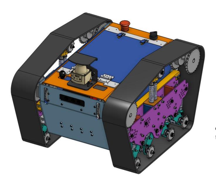
APPENDIX C CAD Drawings
[CAD drawings section]
APPENDIX D Lists
[Lists section]
Hardware Components List
| Part | Brand & Model | Unit Price | Num. |
|---|---|---|---|
| Motors | BAG Motor | 38.99$ | 4 |
| Drives | Talon SRX | 90$ | 4 |
| Gearbox | VersaPlanetary Gearbox | 170$ | 4 |
| Batteries | Milwaukee M18 Battery | 300$ | 12 |
| Nvidia Jetson TX2 | TX2 | 300$ | 1 |
| RapsberryPi | 3B+ | 35$ | 1 |
| IMU | Vector VN-300 | 300$ | 1 |
| Front 3D Camera | Astra Mini | 230$ | 1 |
| Rearview Camera | Pointgrey Blackfly | 300$ | 1 |
| Infrared Camera | Flir Lepton 3.5 | 300$ | 1 |
| LiDAR | SICK TiM5xx | 5000$ | 1 |
| CO2 Sensor | Telaire T6713 | 170$ | 1 |
| 6-axis Robot Arm actuators | Kinova Actuator | 12000$ | 6 |
Software List
| Name | Version | License | Usage |
|---|---|---|---|
| Ubuntu | 16.04 | Various (mostly GPL) | Nvidia Jetson |
| ROS | kinetic | BSD | Robotic framework |
| OpenCV | 3.4.0 | BSD | QR code |
| OpenCV | 3.4.0 | BSD | Landolt C |
| OpenCV | 3.4.0 | BSD | Motion detection |
| Octomap | 1.7.1 | BSD | 2D SLAM |
| VectorNav | - | MIT | IMU |
| CTRE Phoenix API | 5.6 | Closed source | Motors control |
| Sick Tim | 0.0.14 | BSD | LiDAR |
| Pointgrey | 0.13.4 | BSD | Rearview Camera |
| Lepton SDK | - | Closed source | Infrared camera |
| YOLO/Darknet | 1.1.3 | BSD | Hazmat Detection |
| ZBar | 0.1.0 | GNU | QR code |
| VueJS | 2.6.6 | MIT | Web UI |
| RobotWebTools | 3.4.0 | Proprietary | Web UI |
Acknowledgment
The authors would like to thank all team members for their efforts toward this project. A special thanks goes to École de technologie supérieure student club support staff.