RoboCup Rescue 2019 Team Description Paper MRL
Farshid Najafi, Hamed Bagheri, Navid Bonakdar Hashemi, Aliasghar Pouryayvali, Mohammadreza Ahadi, Sayed Mohammad moshgforoush, Mohsen Mojahedpour, Mohammadreza Soltani, Amir Sharifi
Qazvin Islamic Azad University; Mechatronic Research Laboratory (MRL), R&D center
http://www.mrl.ir/mobilerobot · http://moveit.ros.org/
Abstract Rescue robots in urban search and rescue(USAR) have to fulfill several tasks at the same time: localization,mapping, exploration, object recognition, etc. This paper describes the approach used by Team MRL for participation in the 2019 RoboCup Rescue Robot League competition and describes the improvements on robot and introduces a new package of robotic systems for rescue operations. Particularly,a tele-operative light weight robotic system with dexterous manipulator for different rescue missions have been designed and implemented. This robot will operate as a practical system to assist rescue personnel in real disaster situations such as earthquakes and explosions. The main capabilities of the system software are simultaneous localization and mapping, navigation, collision avoidance, sensor fusions, victim detection and exploration. Moreover, the robotic systems are developed on a set of sophisticated mechanical platforms which enhance the mobility ability of tele-operative robots. Also, The new light weight 6-DOF manipulator makes robot capable to accomplish inspection and manipulation tasks decently.
I. INTRODUCTION
R ESCUE Robots are designed to rescue people and/or provide environmental data to the rescue team in order to facilitate a rescue mission. The robots are mainly employed in extreme situations such as natural disasters, chemical/structural accidents, explosive detection, etc. Rescue robot is a type of robot which can instead of rescue personnel enter the disaster scene and carry out rescue work [1] earthquakes take place every year around the world. One of the most important factor in rescue operations is to find and save victims in time.
In this paper, the MRL Advanced Mobile Robotics Lab and its robot is explained. The MRL team is planning not only to take part in Robocup competitions, but also to design and present practical robotic solutions for real life disasters such as earthquakes which are very common in our home country, Iran.
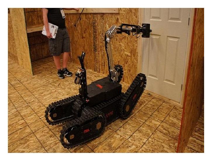
Naji I and Naji IV are two types of rescue robots which were designed with a high power and flexible mechanism, in order to overcome obstacles, are also capable of supporting a powerful manipulator for carrying objects.
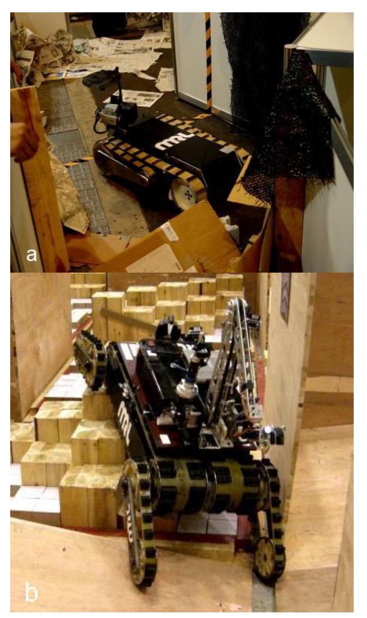
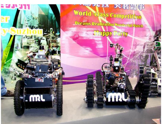
Naji III is a modified version of Naji I which is more powerful and flexible while it is lighter and smaller. In 2008, a new Autonomous robot Naji V was designed for the competitions. There are so many rough and hard terrains in a disaster situation, therefore, the rescue robot should be fast enough and low weigh to pass and explore environment quickly while remain stable. Thus a new mechanical design with 4 arms named Naji VI was developed in 2008 which is equipped to roller cylinders in its bottom. Naji VI with the new stylish is now more stable and efficient than previous ones, plus, using a new mechanical design in NAJI-VI makes this robot more effective in step-fields. In other word, Naji VI is a combination of Naji I and Naji III. By this new design, the capability of Naji I in climbing and the excellences of Naji III in stepfield passing were combined.
For Robocup 2010 competitions, two new robots were designed; Naji VII a tele-operative robot and Viana an autonomous robot. Viana, facilitated by most required sensors, is an autonomous mobile robot to carry out different research programs and is also suitable for the radio off zone arena. Due to improvements in autonomous field the mechanical platform of autonomous robot is improved as well. Therefore, Viana uses a four wheeled differential moving system so that it can cross easily the sloped floor arenas.
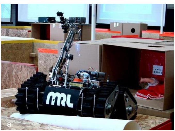
Scorpion, the next generation of tele-operative robot, consists of 4 flippers attached to the main body. Each of these flippers has two links as shown in figure 5. Second part of each flipper has a self-relative rotation to the first part of the flipper with a series of gears. This causes the robot to have a capability of driving both parts of the flipper with one motor and gearbox. This property helps robot to have more flexibility in rough terrain. Another marked property of this robot is using light-weighted materials. For example, fiber carbon, titanium and aluminum are used for the main body and the other parts. Power train system contains two Maxon DC motors coupled with worm gearboxes which speed up the robot up to 0.5m/s. Team MRL achieved 1st place in Mexico 2012 Robocup competition.
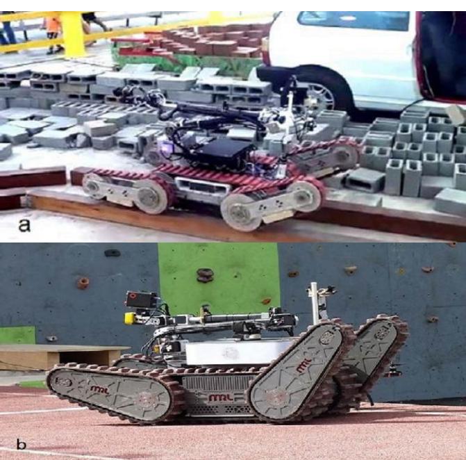
Ario is an unmanned ground vehicle (UGV) designed for a wide range of rescue missions. It easily climbs stairs, rolls over rubble and navigates narrow passages. Its timing pulleys equipped with an integrated suspension system isolates vehicle from road noises and vibrations. Power train system consists of two bevel gearboxes that are directly coupled to driver shafts. Ario moves by tract belt system designed and fabricated specially to deliver a high driving force to the UGV.
A new version of tele-operative robot, Karo, was designed and fabricated in 2015. The main purpose of this improved design, was to achieve reliable mechanical platform, efficient power transmission and sophisticated control system.
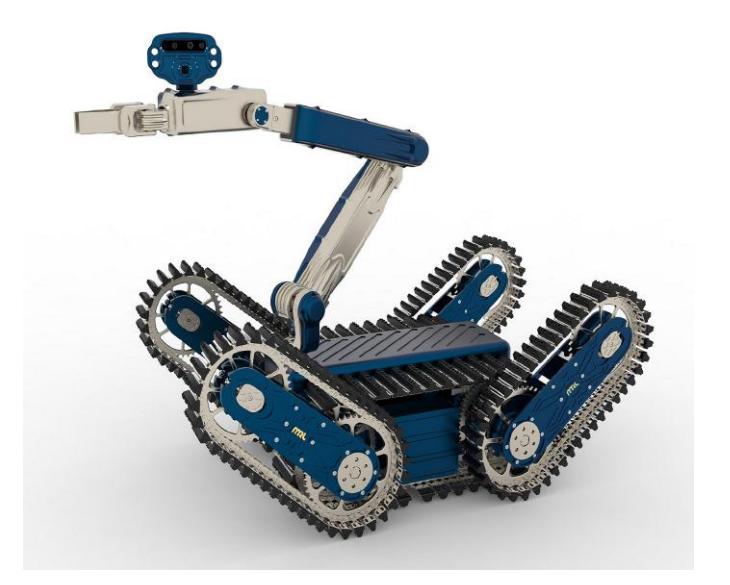
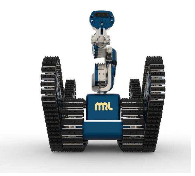
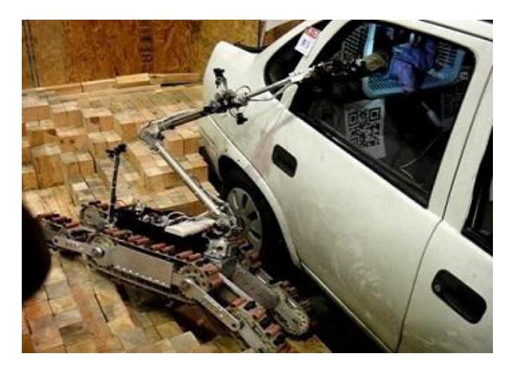
Most of the rescue robots are required to perform tasks in real disaster sites, which demand accurate, lightweight and soft-controlled manipulators. Manipulating objects and finding the victim's location are the most critical tasks in rescue missions. Besides, the manipulator should enjoy a lightweight and rigid structure with sufficient degrees of freedom (DOF).For Robocup 2017 competitions, a new version of the tele-operative robot, Karo plus, was designed and implemented. Karo plus was facilitated by most required sensors and equipped with a hazardous 6 DOFs manipulator. The manipulator had 6 DOFs which is capable of reaching 140 cm. In this manipulator, three out of the six motors are placed before the first link. Power transmissions utilize timing belts, ball screws and sophisticated ball bearing arrangements. These power trains provide an accurate and precise motion for the manipulator end-effector. To increase the reachable workspace of the manipulator, the wrist is mounted on a prismatic joint with 24 cm of stroke.
II. SYSTEM DESCRIPTION
Since most of the idea generation processes and development procedures have been progressed in the laboratory, brief descriptions of hardware, software, communication and human-robot interface are provided in this section.
A. Hardware
The robots hardware is designed for robust longterm missions in disaster areas and will be described in this section:
1) Electronics
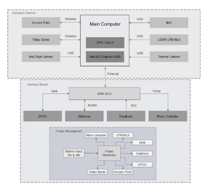
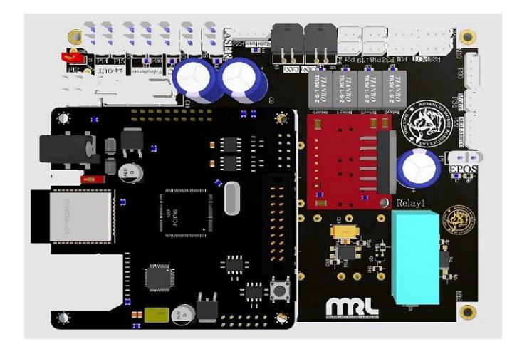
The overall hardware structure is shown in Figure 8. Robot process is performed by two separate units, including an Intel Mini computer and an ARM Cortex M3 board, As shown in the figure 9. The Mainboard consists of two parts, Robots motors control part and power distributor part. Robot control system includes a main unit, which is designed based on ARM-cortex m3 microcontroller, LPC1768. The robots control part uses different connection and protocol such as Ethernet, USB, CAN and RS485 to communicate with the computer, Sensors, motor controllers to receive commands and send feedbacks. This robot is equipped with EPOS motor controllers that connected with the CANopen network to MCU for easy cable management and high-efficiency communication. Servos on the robot are connected into an RS485 chain and connected to the main MCU. Since the voltage requirement of onboard devices is different, four rechargeable LiPo batteries, Two 6-cells, and Two 3-cells are used. Besides, the mainboard is equipped with a unique power management system that used a particular DC-DC converter to supply robots devices. Robots map quality is enhanced by using a stabilizer and an IMU. Also, an analog CO2 sensor is used to get the gas information of the surrounding.
2) Manipulation
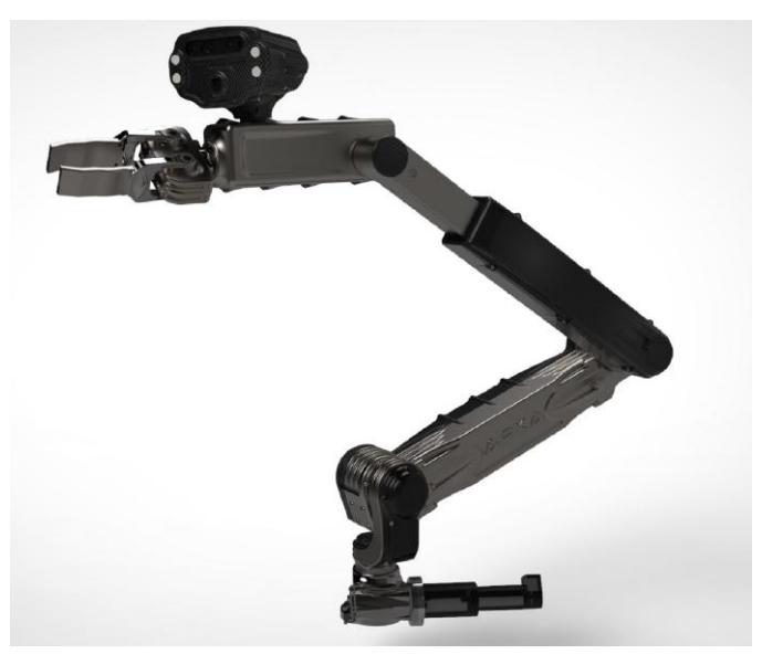
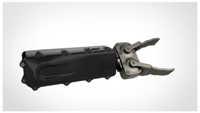
A compact 6 degree of freedom manipulator has been developed. The maximum radius of the manipulator workspace is 135 cm. The manipulator consists of six joint as shown figure10. The first four joints consists of three revolute joints, plus a prismatic one to position the end effector of the manipulator in 3D space. The prismatic actuator has stroke equals to 15 cm which enhances the positioning capability of the arm in 3D space. Manipulation tasks in rescue robot competition require that the deployed manipulator should have high payloads. In the present design, worm gears along with high-quality motors(200w) have been used to provide required torque at the specific joint. In the present design, cables routing are implemented inside the manipulator to increase the safety of the cables in search and rescue operations. A two degree of freedom wrist mechanism has been developed which use worm and spur gearboxes as shown figure11.
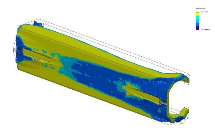
The last joint has been driven by the wrist mechanism is able to rotate 360 degrees. Arm weigh optimization achieved using topology analysis toolbox in SolidWorks figure12.
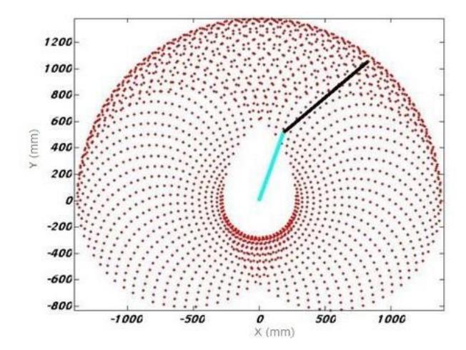
The manipulator has 6 DOFs which is capable of reaching 135 cm as shown in figure13. In this manipulator, three out of the six motors are placed before the first link. Power transmissions utilize timing belts, ball screws and sophisticated ball bearing arrangements. These power trains provide an accurate and precise motion for the manipulator end-effecter. Main links rotate with 15 rpm without considering destructions. End effecter of this serial manipulator is attached to a 3-DOF wrist which provides the manipulator with dexterity to search in tight places. To increase the reachable workspace of the manipulator, the wrist is mounted on a prismatic joint with 24 cm of stroke.
3) Sensors
Shaft Encoder: The robot's base platform is equipped with two Incremental Optical Rotary Shaft Encoders, which makes wheels odometry calculation, possible. According to slope gradient and mostly hash terrains, localization according to odometry measurement could not be a satisfying solution and using additional sensors analysis is unavoidable.
RGB-D Camera: Autonomous Robot is equipped with an Asus Xtion Pro Live RGB-D Camera, mounted on a Pan Tilt unit, which provides depth images in addition of RGB images. One of the primary usages of this sensor is to detect and avoid difficult terrains and obstacles, by using Point Clouds acquired from the camera.
Laser Scanner: 2D map of the environment will be generated using a Hokuyo UTM30-LX LIDAR mounted on a stabilizer. Accordingly, on an inclined surface, it always will stay parallel concerning the ground.
Inertial Measurement Unit: The changes in the attitude of the base platform, will be measured using a 6-DOF inertial sensor, Xsens MTI-100.
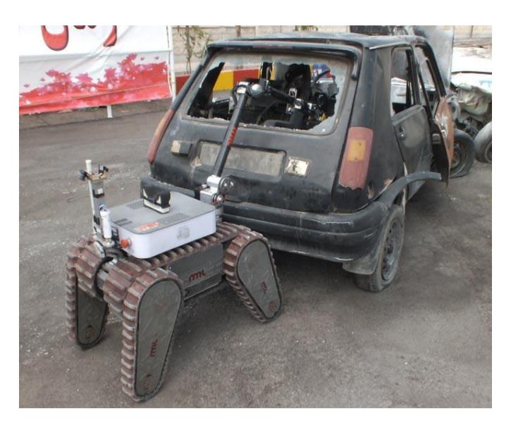
Thermal camera: One of the most important vital signs, for analyzing whether the victim is still alive or not, is temperature of the victim's body. Accordinglya a Thermal camera has mounted on the end effector of manipulator of the tele-operative robot (ARKA).
CO2 sensor: In order to find out, whether the victim is breathing or not, "MQ-9" sensor is being used on ARKA
Thermal Camera: Detection and position estimation of victims are being accomplished by equipping autonomous robot with a Thermal Image Optris PI230, which is capable of synchronous capturing of visual and thermal images.
Analog Cameras: Four analog cameras which are mounted on the manipulator and body of the tele-operative robot, assists operator to drive the robot and detect victims.
4) Tele-Operative Robot (ARKA) Locomotion
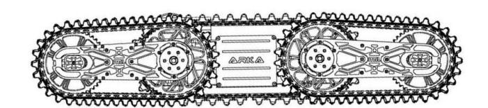
There are three major categories of locomotion systems in the field of rescue, reconnaissance or Surveillance robots; wheeled, tracked, or legged systems. Tracked systems are mostly used because of their ability to move on uneven terrains and overcome to obstacles. Tracked locomotion system is chosen for ARKA robot to obtain these abilities. The two tracked layout is augmented by flipper tracks on both the front and back, independently tilted, but those tracks are driven by the main track motors.
5) Static Analysis of Tele-Operative Robot (ARKA)
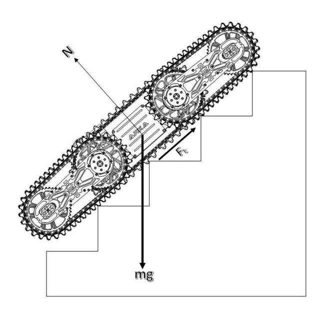
Using the kinetic and potential energy expressions, and applying Lagrange's equations for a constrained or unconstrained mobile robotic system, the static model can be obtained. With considering a simplified model as shown in Figure 16, The required torque to rotate the robot about this vertical axis is given by:
$$T = I\alpha \tag{1}$$
Moving up a 45 degrees inclined plans is one of the most challenging situations that may encounter. The tangential force (traction force) need to push the robot up the inclined plane in static quasi-static equilibrium is given by the following equation:
$$F_t = mgsin\theta \tag{2}$$
Therefore output torque of the power train can be calculated on:
$$T = F_t R \tag{3}$$
Where R is the radius of the sprocket.
6) Power Transmission of Tele-Operative Robot (ARKA)
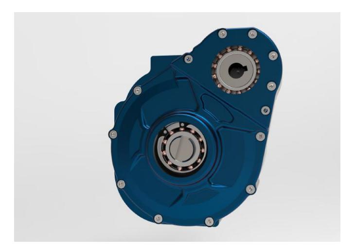
In the present design movement of the robot on the ground is achieved using tracked locomotion system. This system consists of the main traction mechanism and flipper arms. The power train for the locomotion system consists of Maxon motor (200 watts), Spur and planetary gearbox. Chain drives and track mechanism. A combination of an in-house built planetary gearbox is used in the robot To reduce the overall size of the robot in order to achieve higher mobility in narrow spaces as shown in figure17.
The robot is able to move on rough trains. Including stairs, elevated Ramps, Step filled and sand and gravels. The second advantage of using compact planetary gearboxes is to concentrate the main mass to the power train in the middle of the robot. The second advantages reduce the main movement of inertia of the robot and to achieve higher angular acceleration about the vertical axis of the robot where:
$$I = \int r^2 dm \tag{4}$$
and alfa are the main movements of inertia and angular acceleration of the robot respectively.
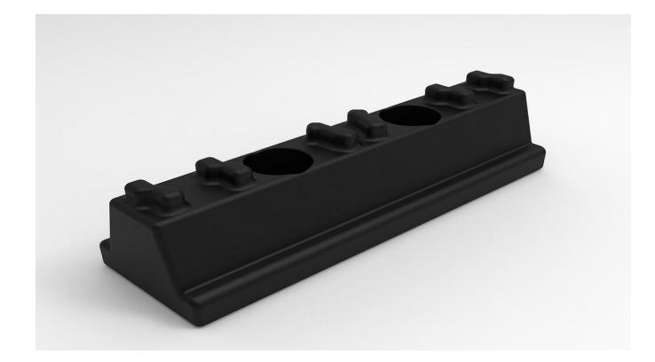
To achieve the highest traction for the robot, special plastic partsmade of robber have been developed as shown in figure18.
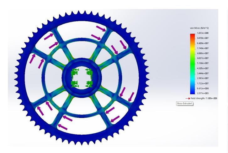
These parts are installed on the chain drive mechanism and have a special shape to provide more contact and engagement between the tracked mechanism and the ground. In addition, the rubber can significantly damp the shock loads applied from the ground to the robot. In order to make sure that chain sprocket is able to tolerate the applied loads at extreme conditions, finite element analysis is done using SolidWorks simulation toolbox.The results are shown in figure19.
B. Software
Brief descriptions of software components and their functions are provided here.
1) Simultaneous Localization and Mapping
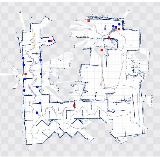
In the past years the use of Occupancy Grid Maps due to the need for key functions required for mobile robots such as localization, path planning, collision avoidance, have been increased [2]. The SLAM itself has been an active topic in the past decade. Since the USAR environments are unstructured and non-planarity, normal planar indoor solutions [3] are not applicable. Another downside is that they rely heavily upon accurate odometry which is noisy and uncertain or even unavailable. These facts trigger the need for a flexible SLAM system with full motion estimation. Recent research in this field [4] have resulted in developing a robust SLAM system with 6 DOF motion estimation. Improving the accuracy of the map, a modern LIDAR system with high update rate have been mounted on the robot too. In order to give an overall consideration of the disaster site to the firefighters instead of giving them piece by piece information, a map merging framework has been developed which finds transformation between two maps and merges them accordingly. In addition to 2D mapping, in order to generate a 3D model of environment, an open-source framework which is based on octrees and uses probabilistic occupancy estimation has been used [5]. The generated 3D model is used for detection of impassable trains in the environment.
2) Autonomy, Path Planning and Navigation
Navigating through the unknown USAR environment is the main task of the robots in the Robocup Rescue. Moreover they must collect information regarding the environment consisting victims positions, QR codes, objects and other points of interest. In order to achieve these goals, a highly modular system has been developed. It consists of several layers such as behavior control, global path planner and trajectory generation. The high level behavior of the robot chooses between moving towards a potential victim and exploring the environment. The global planner task is to find the goal points with the aim of maximum coverage and minimum distance travelled. It tries to find the shortest tour which covers the whole environment. Due to the fact that the environment is unknown and the map is unavailable its extremely challenging to find the best tour, but as the map becomes larger, the output result becomes more reasonable. Another challenge of the global planner is that the task of finding the shortest tour is computationally expensive, accordingly the techniques for finding the shortest tour in the dynamic environments have been used and the results were promising. In contrast to other path planning methods, like wall following [6] or frontier exploration [7], the presented method significantly increases the performance of the robot. After finding the goal point and a path towards it, trajectory planner starts its job by generating trajectories that fit into the current state of the robot and the goal that it tries to reach. Since Adrina has a lot of motion constraints, the available trajectory generation methods [8] [9] don't provide a satisfying result; hence there was a need for developing a customized trajectory generator which fully accommodates with Adrina. Recovery behaviors [10] also have been developed so that when the robot is having a collision, they take over and handle the situation. Future works in this fields are multi robot support in global path planner, better detection of the topology of the environment, improving motion planning, failure recovery behaviors, etc.
3) Arm Planning
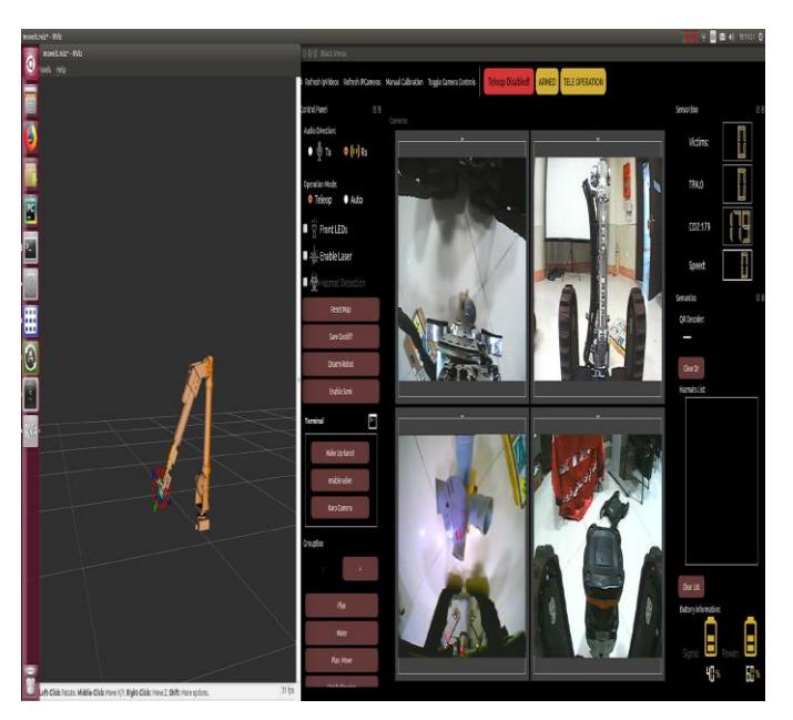
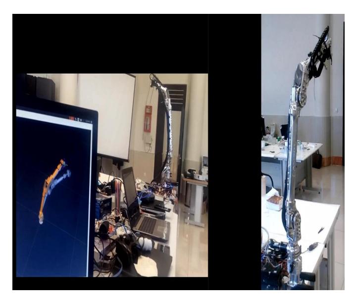
In order to develop a manipulator application, at least two packages are required. In our work, we employ the state of art software tool- MoveIt [http://moveit.ros.org/] to realize an easy-to-use procedure for developing advanced robotics applications as shown in figure21.
System Modeling and Description: The robotic system can be modeled in tree structures. In ROS, a Unified Robot Description Format (URDF) is designed to describe the system model configuration. URDF file is an XML specification recorded the whole physical information of link, joints, properties, actuators, and sensors[11]. We used a community toolkit SW URDF exporter, which is a SolidWorks add-in, to conveniently export of CAD models into URDF file. Thus we can realize a complete file configuration describing a mobile manipulation platform. Moreover, the models can be shown in Rviz as given in figure22.
Planning and State of Art Algorithms Integration: Moveit has three different planners on it :
- OMPL planner
- CHOMP planner[12].
- STOMP planner [Authors: Mrinal Kalakrishnan, Sachin Chitta, Evangelos Theodorou, Peter Pastor, and Stefan Schaal, STOMP: Stochastic Trajectory Optimization for Motion Planning]
The OMPL package, which provides a variety of motion planning algorithms to control the different robots. MoveIt! Allows users to interact with motion planners simply. We selected the OPML among the planner mentioned above.
C. Communication
The robots have been equipped with MikroTIK Networks 802.11a/b/g NetMetal5 Access Point/Bridge. Choosing IEEE 802.11a 5 GHz standard has allowed achieving the maximum efficiency without having the difficulties of 802.11b and 802.11g. 1300MW power ensures robust signal to overcome long distances. Controlling tele-operated Robot, video and sound streaming, system diagnostics, sensors feedback, visualizing procedures and localization and mapping in a remote station are the most common usages of this type of communication.
D. Human-Robot Interface
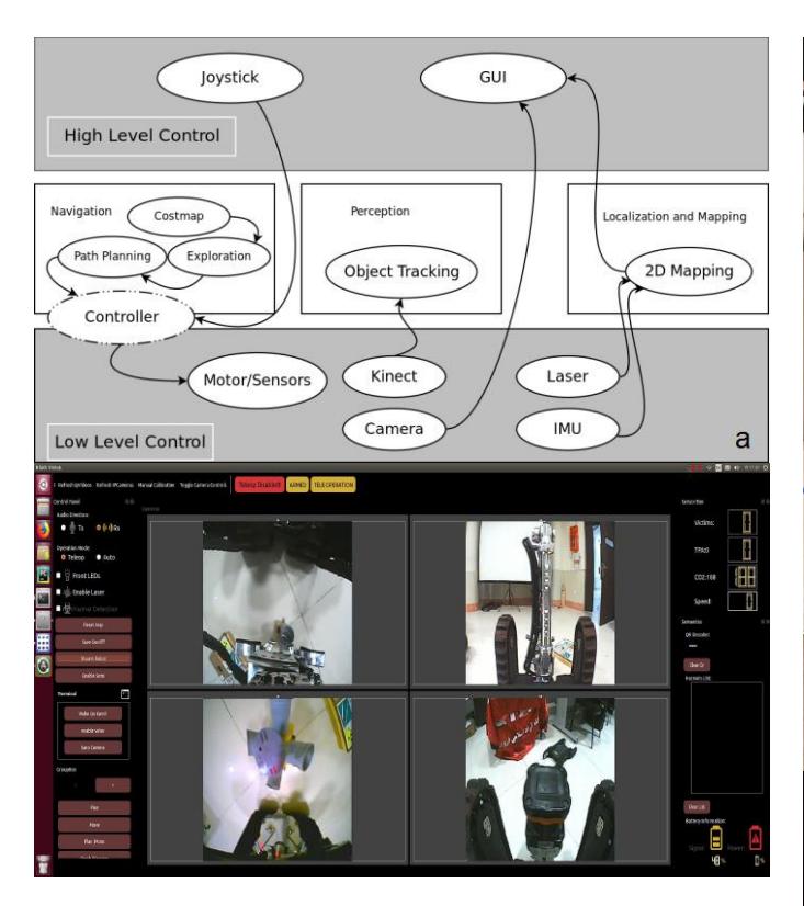
Human supervision and control of the robots are accomplished using two independent but closely packed software. Since they are integrated with ROS [10] as the middleware, and their cores are different (ROS does not have a built-in system to allow a single node to connect to multiple ROS cores), the task to create a integrated GUI is extremely difficult. They have to be designed in such a way that they seem like a single software. The colors for user interface are chosen based on their meaning, the controls are minimal and only provide a high level control over robots. They are also highly dynamic, thanks to rqt gui plug-in, their features can be adopted and customized as needed. The autonomous robot can be started in fully autonomous mode and the controls provided by the interface is just used for further diagnostics and confirmation of the victims. The tele-operative robot GUI is mainly used for visualization purposes such as video streaming and sensory data but it also controls the mapping and armed or unarmed state of the robot. The commands from station only sent to the robot if the state is armed, this feature ensures that no unintentional commands is sent to the robot, just like armed mode in UAV robots. In addition to joysticks, the tele-operative robot also can be controlled using keyboard or other types of controllers, using an abstract ROS node, which can be easily modified according to the type of joystick.
III. APPLICATION
Description of the team's approach to the competition and field applications.
A. Set-up and Break-Down
In the rescue operation, it is desirable to set-up and break down the robot operation system in less than 10 minutes. So the robot should be designed modular to set-up and break down in minimum time. An Operator Control Unit (OCU) including a small form factor PC, joystick, access point, antenna, monitor and waterproof case so that the operator can set up and drive in a user-friendly environment.
B. Mission Strategy
As mentioned above, this year we have designed the new rescue robot with more capability and some new specification. So, we would like to participate in all of the challenges especially Mobility and Dexterity test methods to measure the robot's capability. In addition, As a focus of our research is reducing workload for operators and we try to participate in EXP Tasks to improve our robot ability for moving autonomously in the fields and also ameliorate robot's map quality.
C. Experiments
A simple test arena is provided in the laboratory to put the robots into the test. This test arena includes, stairs, inclined planes, step-fields, continuous and crossing ramps, pipe-steps, pipe-stars and victims.
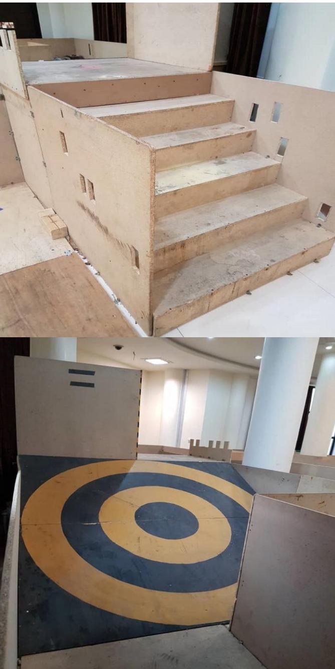
D. Application in the Field
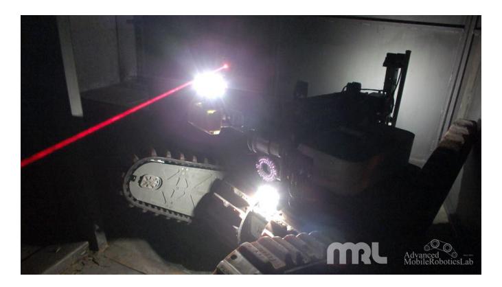
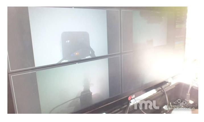
Karo accomplished a mission in a fire station's test bench. This mission evaluated the robot's performance as a surrogate. this cooperation was arranged to put the technical features of the rescue robots in some prespective.
IV. CONCLUSION
We have developed our past generation rescue robot with high mobility performance and arm performance. We will evaluate these performances with RRL and use it as a reference for future development. Besides, Several remarkable lessons, about robots' functionality, are learned from taking part in RoboCup Rescue competitions and accomplishing several practicing missions; the most notable one is that developing different aspects of technology on rescue robots make them capable of executing their duties more decent, from a fundamental task to more complicated ones. However, durability, stability, and robustness are some game-changer factors which prevent the performance of systems from decreasing during the time, regardless of condition's changes.
APPENDIX A TEAM MEMBERS AND THEIR CONTRIBUTIONS
• Farshid Najafi Supervisor • Hamed Bagheri Team leader,Electrical design • Navid Bonakdar Hashemi Mechanical design
• AliAsghar Pouryayvali Mechanical design
• Alireza H.M.Hosseini Mechanical component fabrication • Mohammadreza Soltani Mechanical design • Mohammadreza Ahadi Embedded system programming • Mohsen Mojahedpour Embedded system programming • Sayed Mohammad Moshgfroush image processing, Software Design • Amir Sharifi path planning, Software Design • Ahmadreza Zibaie image processing, Software Design • Qazvin Islamic Azad University Sponsor
APPENDIX B CAD DRAWINGS
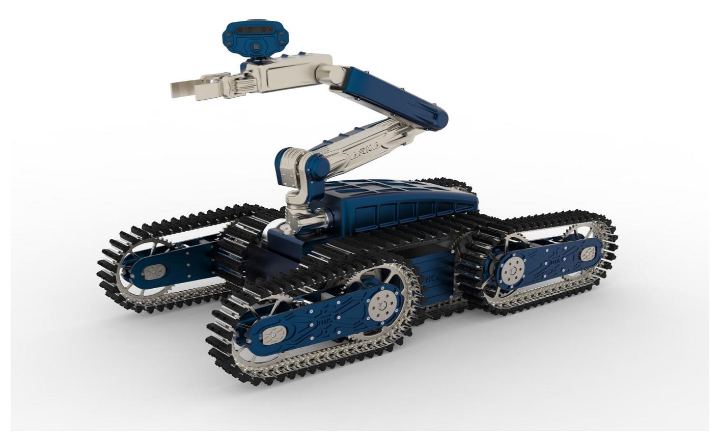
Figure 27 illustrates the CAD drwings of ARKA, teleoperative rescue robot.
APPENDIX C LISTS
Several system and component specifications are provided in this appendix.
A. Systems List
Several features of tele-operative rescue robot with manipulation system and operator station information are provided below.
MANIPULATION SYSTEM
| Attribute | Value |
|---|---|
| Name | ARKA |
| Locomotion | tracked |
| System Weight | 95kg |
| Weight including transportation case | 100kg |
| Transportation size | 0.9 x 0.8 x 0.7 m |
| Typical operation size | 0.8 x 0.6 x 0.6 m |
| Unpack and assembly time | 210 min |
| Startup time (off to full operation) | 8 min |
| Power consumption (idle/ typical/ max) | 60 / 560 / 1000 W |
| Battery endurance (idle/ normal/ heavy load) | 90 / 40 / 20 min |
| Maximum speed (flat/ outdoor/ rubble pile) | 0.85 / 0.65 / 0.35 m/s |
| Payload (typical, maximum) | 50 kg |
| Arm: maximum operation height | 135 cm |
| Arm: payload at full extend | 5kg |
| Support: set of bat. chargers total weight | 5kg |
| Support: set of bat. chargers power | 300W (11-25V DC) |
| Support: Charge time batteries (80%/ 100%) | 45 / 60 min |
| Cost | 35000 USD |
OPERATOR STATION
| Attribute | Value |
|---|---|
| Name | Operator Control Unit (OCU) |
| System Weight | 5kg |
| Weight including transportation case | 5kg |
| Transportation size | 0.7 x 0.4 x 0.3 m |
| Typical operation size | 0.7 x 0.4 x 0.3 m |
| Unpack and assembly time | 1 min |
| Startup time (off to full operation) | 5 min |
| Power consumption (idle/ typical/ max) | 60 / 80 / 110 W |
| Battery endurance (idle/ normal/ heavy load) | 2 / 2 / 2 h |
| Cost | 3500 USD |
B. Hardware Components List
List of notable components of ARKA and the Operator station is provided in table below.
HARDWARE COMPONENTS LIST
| Part | Brand & Model | Unit Price | Num. |
|---|---|---|---|
| Drive motors | Maxon 200 W | USD 588.50 | 2 |
| Drive gears | Planetary Gearhead | USD 322.25 | 2 |
| Drive encoder | Encoder HEDS 5540 | USD 99.88 | 2 |
| Motor drivers | custom designed | - | 2 |
| DC/DC | MKW50 | USD 50 | 5 |
| Batteries | Genstattu Lipo | USD 230 | 3 |
| Micro controller | LPC1768 | USD 8 | 6 |
| Computing Unit | Intel Mini PC | USD 500 | 1 |
| WiFi Adapter | UBNT Bullet M5 | USD 90 | 1 |
| IMU | Xsens | 1200 | 1 |
| Cameras | Hi-vision cctv | USD 25 | 4 |
| Infrared Camera | Optris thermal camera | USD 6000 | 1 |
| 6-axis Robot Arm | custom designed | - | |
| Aerial Vehicle | Phantom-3 | USD 1100 | 1 |
| Rugged Operator Laptop | Intel Mini PC | USD 500 | 1 |
C. Software List
List of all relevant software packages which is used in the robots software system.
SOFTWARE LIST
| Name | Version | License | Usage |
|---|---|---|---|
| Ubuntu | 16.04 | open | |
| ROS | Kinetic | BSD | |
| PCL [13] | 1.7 | BSD | |
| OpenCV [14], [15] | 4.0.0 | BSD | |
| Hector SLAM [4] | 0.3.4 | BSD | 2D SLAM |
| Octomap | 1.6.9 | BCD | |
| Moveit Version | 0.10.0 | BCD |
References
[1] J. Casper and R. Murphy, "Human-robot interaction during the robot assisted urban search and rescue effort at the world trade center," in IEEE Transactions on Systems. IEEE, 2003, p. 367385. [2] S. Thrun, "Learning occupancy grids with forward models," in Autonomous Robots. Springer, 2003. [3] G. Grisetti, C. Stachniss, and W. Burgard, "Improved techniques for grid mapping with rao-blackwellized particle filters," in IEEE Transactions on Robotics. IEEE, 2007. [4] S. Kohlbrecher, J. Meyer, O. von Stryk, and U. Klingauf, "A flexible and scalable slam system with full 3d motion estimation," in International Symposium on safety, Security, and Rescue Robotics. IEEE, 2011. [5] A. Hornung, K. M. Wurm, M. Bennewitz, C. Stachniss, and W. Burgard, "An efficient probabilistic 3d mapping framework based on octrees armin hornung," in Autonomous Robots Journal. Springer, 2013. [6] P. van Turennout, G. Honderd, and L. J. van Schelven, "Wall-following control of a mobile robot," in Robotics and Automation. IEEE, 1992. [7] S. Kohlbrecher, J. Meyer, T. Graber, K. Petersen, U. Klingauf, and O. von Stryk, "Hector open source modules for autonomous mapping and navigation with rescue robots." RoboCup Symposium 2013, 2013. [8] D. Fox, W. Burgard, and S. Thrun, "The dynamic window approach to collision avoidance," in IEEE Robotics and Automation Magazine, vol. 4. IEEE, 1997, pp. 23–33. [9] B. Gerkey and K. Konolige, "Planning and control in unstructured terrain," in International Conference on Robotics and Automation. IEEE, 2008. [10] M. Quigley, K. Conley, B. Gerkey, J. Faust, T. B. Foote, J. Leibs, R. Wheeler, and A. Y. Ng, "Ros: An open-source robot operating system," in International Conference on Robotics and Automation. Open-Source Software workshop,, 2009. [11] J. X. Hao Deng and Z. Xia, "Mobile manipulation task simulation using ros with moveit," in IEEE International Conference on Real-time Computing and Robotics (RCAR). IEEE, 2017. [12] M. Z. Nathan Ratliff, "Covariant hamiltonian optimization for motion planning," in IEEE International Conference on Robotics and Automation. IEEE, 2009, pp. 1164–1193. [13] R. B. Rusu and S. Cousins, "3D is here: Point Cloud Library (PCL)," in IEEE International Conference on Robotics and Automation (ICRA), Shanghai, China, May 9-13 2011. [14] P. Viola and M. Jones, "Rapid object detection using a boosted cascade of simple features," in Computer Vision and Pattern Recognition, 2001. CVPR 2001. Proceedings of the 2001 IEEE Computer Society Conference on, vol. 1, 2001, pp. I–511–I–518 vol.1. [15] R. Lienhart and J. Maydt, "An extended set of haar-like features for rapid object detection," in Image Processing. 2002. Proceedings. 2002 International Conference on, vol. 1, 2002, pp. I–900–I–903 vol.1.