RoboCup Rescue 2019 Team Description Paper Mars-Rescue
Qingwen Xu, Zeyong Shan, Ruijian Li, Xiaoling Long, Soren Schwertfeger
ShanghaiTech University
https://robotics.shanghaitech.edu.cn · https://robocup-rescue.github.io/team_description_papers/
Abstract MARS-Rescue is a new team for the RoboCup Rescue Competition. We are using a very small (23cm wide) and lightweight (4.2kg) robot without a manipulator. Our tracked robot has four individually actuated flippers and two drive motors. Our main sensor is a Intel Realsense D435i RGBD camera, that we use for visual SLAM. Our team is concentrating on autonomous functions and we plan to execute most tests autonomously.
I. INTRODUCTION
Rescue robotics, especially at RoboCup Rescue has often concentrated on fairly big robot with manipulators [1], [2], [3], [4]. In contrast, it is our team's goal to build very small and cheap, but capable rescue robot for searching in small, inaccessible areas, such as collapsed buildings. Since our robot should be small we don't mount a manipulator. When entering a rubble pile it is quite likely that radio communication will be lost. We thus aim for full autonomy [5] in most test elements of RoboCup Rescue. For that mapping [6] is essential. Since we want a small and cheap robot that is operating in a very 3D environment we are not using a laser scanner, but a RGB-D camera that also works outdoors: an Intel Realsense D435i. For our robot we use lots of open source software and the ROS middleware. In the spirit of [7] we plan to share all of our software as open source after the 2019 competition.
Our team is supported by ShanghaiTech University, the School of Information Science and Technology (SIST) and the ShanghaiTech Automation and Robotics Center (STAR Center). The MARS Rescue team is consisting of PhD, graduate and undergraduate students from the Mobile Autonomous Robotic Systems Lab (MARS Lab) under the supervision of Prof. Soren Schwertfeger.
All authors are with ShanghaiTech University.
Next to participating in the RoboCup Worldcup 2019 in Sydney, Australia, we will also participate in the RoboCup German Open 2019 in Magdeburg, Germany.
A. Improvements over Previous Contributions
This is the first year of our participation.
II. SYSTEM DESCRIPTION
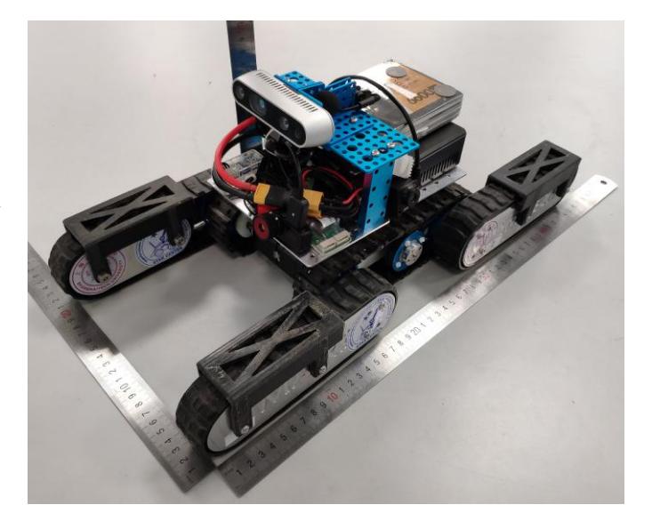
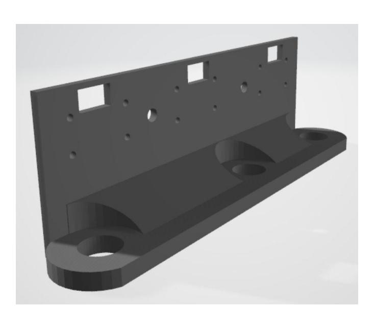
Our small rescue robot is build with commercially available electronics and custom mounting structures. Those are aluminum plates (e.g. on the Flippers, as shown in Figure 1) and a main mounting structure consisting of two parts (one is the mirror of the other). In the beginning we were 3D printing the part - see Figure 6. The new version of our robot has this part made of aluminum by our school's 5-axis CNC machine.
A. Hardware
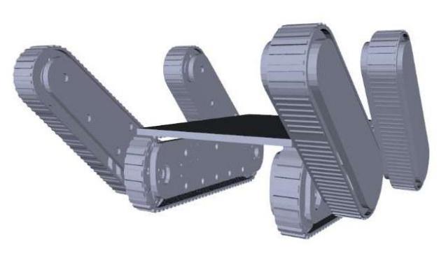
The robot is 4.2kg weigh, 48 cm long, 23 cm wide, 22cm high which include the Intel Realsense D435i camera. Our robot has four flippers so that it can go through the small obstacles. It is equipped with 4 cameras, the D435i at the front is for visual odometry and mapping, one infrared camera for victim identification, two Ueye cameras on left and right for QR code and victims. It has one CO₂ sensor. It is also equipped with microphone and speaker for audio communication.
1) Locomotion
Our small rescue robot uses tracks to move around. We use a total of six Dynamixel motors, the middle two are used to drive the robot, and the other four control the corresponding flipper. In order to ensure the maximum torque of the motor, we use a five-axis machined titanium part at the junction of the motor and the axle. We also added extra baffles to the flipper to reduce the chance of the track falling off.
2) Power
In order to support our core mini PC and all motors, we chose a 6600mAh battery. In our experiments, it can support all components for about one hour of normal operation, which is enough for RoboCup mission. A larger battery will cause the center of gravity to shift and the flipper load to increase, so we have not used it.
3) Electronics
We used a USB to TTL module to establish communication between the motor and the mini PC. By modifying the Dynamixel code, the robot can now achieve a control frequency of 100 Hz.
4) Computation
The mini PC is equipped with an i7 lowvoltage processor, which provides enough computing power to support the operation of the code, while ensuring low power consumption and extended battery life. We also provides optimized algorithm such as the 3D grid mapping algorithm to ensure that the system can run and update in real time. More details are described in the software section.
B. Software
All the software of MARS-Rescue (listed in Table IV in the Appendix) are developed based on Robot Operating System (ROS). Each module is introduced in the following sections.
1) Low level control
We are using a simple PID based control to set the speeds of the Dynamixel motors.
2) Communication protocol
When transporting images from the robot to operator station, the speed and bandwidth are the top requirements. Thus we use RTP protocol of GStreamer to transport packets.
3) Localization and mapping
In order to achieve autonomy, it first needs to know the pose of robots, and 3D pose particularly in this dissertation. For 2D SLAM, which is mostly in LIDAR approach, is pretty mature such as Gmapping [8], Cartographer [9] and Hector-SLAM [10]. Regarding RGBD to 2D LIDAR, there is also an existing ROS package and the result is not so good during the simple test. Regarding 3D approaches, as known in SLAM territory, ORB-SLAM [11] and ORB-SLAM v2 which extended to stereo and RGBD, is a complete and relative robust system. During the handheld experiments, it works mostly in featurerich scenes but does not fit the rescue scenario where strong motion and featureless are very common. After this result, it is convinced the approach should combine to IMU sensor.
Similar to mono-SLAM, IMU combined SLAM, (since most work on front-end, also just call VIO) also can be divided into filter-based and optimization-based. However, maximum a posteriori estimation in Bayes and optimizing a least square are equal and also existing filter approach SR-ISWF(Square Root Inverse Sliding Window Filter) use inverse filter for iterative relinearization, achieve the same essence to optimization-based approaches. Two different algorithms ROVIO [12] and VINS-mono[13] have been tested. ROVIO is filter-based and is just a visual-inertia odometry. It is then included in Maplab, which consists of ROVIO-Li (ROVIO with relocalization) online front-end and other rich offline map-process algorithm. Thus it is more suitable for trajectory and map evaluation. Moreover, ROVIO is monocular and sparse, add depth information for tracking is feasible, however, when combining depth information to build semi-dense maps for ground-navigation, it is hard to rewrite the offline map-process which contains loop closure and optimation. During the test in rescue scene of handheld, VINS-mono also over-perform ROVIO.
Compared to ROVIO, VINS-mono is also a monocular approach, however, contains the whole SLAM modules. It first does feature tracking and IMU preintegration parallelly, and do visual-inertial alignment to calibration gyroscope bias, initialize velocity, gravity vector and metric scale. Then proceed tightly coupled monocular VIO, and do relocalization using BOW2, do global pose graph optimization. The pose estimated is in nice quality under handheld situation. Thus the modification has done to add depth points base on the keyframes. However in wheels situation, such as normal vehicles, the IMU is not fully motivated. Because vehicles usually perform constant local acceleration and no-rotation motion, which causes scale and 3-dof global orientation unobservable respectively. Our solution is to combine depth to get the absolute scale.
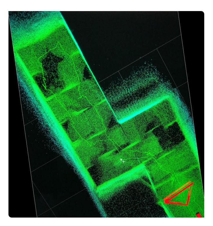
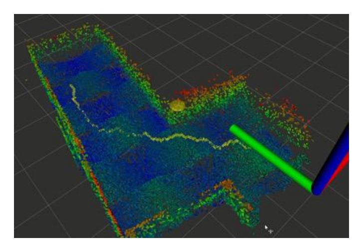
In the mapping part, due to the addition of depth information, we can generate 3D dense point cloud and octomapbased 3D grid map in real time in indoor scene. We can also downsample and filter the pcl point cloud to better serve navigation.
4) Victim detection
To detect the victims, we incorporate several sensors including CO2, thermal, RGB and RGB-D sensors. The CO2 sensor is mounted in front of the robot to detect the density of CO2. The thermal sensor is used to detect the change of heat so that we can determine whether there is an victim. To avoid the interface of indoor temperature, we set a suitable threshold for heat detection. In addition, two side-view RGB camera and one forward-looking camera are exploited for QR code, motion and hazmat detection. Since the field of view (FOV) of the forward-looking camera is limited, the left-looking and right-looking cameras are used to broaden the total FOV.
C. Communication
We use standard 802.11g WiFi hardware. Most messages just use ROS. We don't transmit the audio and video via ROS messages but are using GStreamer. For that we are using ROS nodes converting between GStreamer and ROS on both ends (robot and operator station).
We also plan to support wired operation of the robot. For that we will use just a two write cable. We will transmit power and data over this cable. We will use 110/220V AC and PowerLine adapters on both sides, giving us 500 Mbps on a long range (at least 50m). The robot will also have small AC to DC (15V) converter with 20A. On the operator side we have a DC to AC (car) converter or can use normal AC power.
D. Human-Robot Interface
We use a normal joystick for control. A ROS GUI is used as main user interface. Since our emphasis is on autonomy we did not optimize our user interface for tele-operation.
III. APPLICATION
Our robot is very small and portable. Setup and operation are quite easy.
A. Set-up and Break-Down
Our robot is stored fully assembled in a small bag. What is left to do is to insert the battery and switch it on.
B. Mission Strategy
We are concentrating on autonomous operation of the robot - we aim to execute all tests fully autonomous. Because of our small size we are not very mobile, for example we cannot drive on the step-fields. We also do not feature a manipulator.
C. Experiments
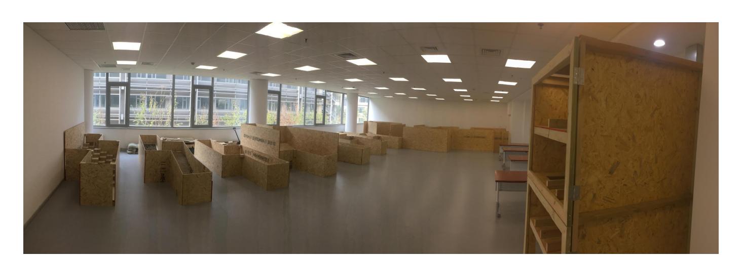
In 2017 our group hosted SSRR 2017, for which we had build standard test elements in 60cm size: http://www.ssrr-conference.org/2017/pages/demo/. We still have this arena. Additionally we have one full-size test element which we can equip with different tests. Our autonomy software is flexible to work in both 60cm and 120cm arenas. We use the arenas to extensively test our algorithms.
D. Application in the Field
Since this our first year our hardware is not very advanced yet. There could also be done a lot regarding usability of the software. The mobility of the robot is also not really that great - it seems not sufficient for general rubble piles. But we can imagine special scenarios of confined space with not too difficult terrain (the floor of a collapsed building for example) where a hardened version of our robot would be able to perform well.
IV. CONCLUSION
Our small MARS Rescue Robot is cheap but features powerful sensors and software. We heavily rely on open source software and will share our solution after the competition. We hope to perform well in the competitions.
APPENDIX A TEAM MEMBERS AND THEIR CONTRIBUTIONS
MAN X means, that this person is responsible for the autonomy software for the specific test method.
Team Members and Their Contributions
| Member | Role | Contributions |
|---|---|---|
| Qingwen Xu | Team leader | GStreamer; Autonomy |
| Shan Zeyong | vSLAM; Mechanical design | |
| Ruijian Li | vSLAM; Mechanical design | |
| Xiaoling Long | Planning; Networking; MAN 4 | |
| Hongyu Chen | CO2; Motion Detection; MAN 3 | |
| Haofei Kuang | Infrared; QR Code; MAN 4 | |
| Zhenpeng He | URDF; GUI; MAN 2 | |
| Yijun Yuan | Autonomous Flippers; MAN 6 | |
| Cai Jianxiong | Hazmat Detection; MAN 5 | |
| Song Bai | Control; Navigation; MAN 1 | |
| Jiawei Hou | Autonomy EXP 1 | |
| Fang Chen | Mechanical design | |
| Soren Schwertfeger | Advisor |
TABLE I MANIPULATION SYSTEM
| Attribute | Value |
|---|---|
| Name | MARS |
| Locomotion | tracked |
| System Weight | 4.2kg |
| Weight including transportation case | 10kg |
| Transportation size | 29 x 24 x 13 cm |
| Typical operation size | 48 x 23 x 22 cm |
| Unpack and assembly time | 120 min |
| Startup time (off to full operation) | 10 min |
| Power consumption (idle/ typical/ max) | 25 / 150 / 270 W |
| Battery endurance (idle/ normal/ heavy load) | 240 / 120 / 60 min |
| Maximum speed (flat/ outdoor/ rubble pile) | 0.28 / 0.28 / - m/s |
| Payload (typical, maximum) | 1/ 3 kg |
| Support: set of bat. chargers total weight | 632g |
| Support: set of bat. chargers power | 72W (100-240V AC) |
| Support: Charge time batteries (80%/ 100%) | 40 / 60 min |
| Support: Additional set of batteries weight | 0.5kg |
| Cost | CNY 26,000 |
TABLE II OPERATOR STATION
| Attribute | Value |
|---|---|
| Name | Dell Latitude |
| System Weight | 2kg |
| Weight including transportation case | 3kg |
| Transportation size | 0.4 x 0.4 x 0.2 m |
| Typical operation size | 0.4 x 0.3 x 0.4 m |
| Unpack and assembly time | 1 min |
| Startup time (off to full operation) | 1 min |
| Power consumption (idle/ typical/ max) | 60 / 80 / 90 W |
| Battery endurance (idle/ normal/ heavy load) | 8 / 4 / 2 h |
| Cost | USD 2,000 |
TABLE III HARDWARE COMPONENTS LIST
| Part | Brand & Model | Unit Price | Num. |
|---|---|---|---|
| Drive motors | DYNAMIXEL XM430-W350-R | USD 240 | 4 |
| DYNAMIXEL XM430-W210-R | USD 240 | 2 | |
| Batteries | Lipo 6600mAh 14.8V 4S 35C/70C | CNY 549 | 1 |
| Micro controller | Dynamixel built-in controller | 6 | |
| Computing Unit | Intel NUC7i7DNK miniPC | CNY 4,838 | 1 |
| Cameras/IMU | Intel Realsense D435i | USD 199 | 1 |
| Camera | Ueye XS mini | CNY 3,000 | 2 |
| Infrared Camera | Seek Compact PRO | USD 499 | 1 |
| Microphone | Universal microphone | CNY 16 | 1 |
| Speaker | yAyusi speaker | CNY 38 | 1 |
| CO2 Sensor | CCS811 HDC1080 | CNY 128 | 1 |
| Battery Chargers | iMAX B6mini | CNY 190 | 1 |
TABLE IV SOFTWARE LIST
| Name | Version | License | Usage |
|---|---|---|---|
| Ubuntu | 16.04 | open | |
| ROS | Kinetic | BSD | |
| GStreamer | 1.0 | LGPL | Image Transport |
| OpenCV | 3.4.0 | BSD | Thermal Detection |
| OpenCV | 3.4.0 | BSD | Motion Detection |
| OpenCV | 3.4.0 | BSD | Hazmat detection |
| VINS-Mono | GPLv3 | 3D SLAM | |
| MARS-RoboCup-GUI | 1.0 | closed source | Operator Station |
| MARS-Auto-Planning | 1.0 | closed source | Auto Navigation |
References
- R. Sheh, S. Schwertfeger, and A. Visser, "16 years of robocup rescue," KI-Kunstliche Intelligenz, vol. 30, p. 267–277, 2016.
- A. Jacoff, R. Sheh, A.-M. Virts, T. Kimura, J. Pellenz, S. Schwertfeger, and J. Suthakorn, "Using competitions to advance the development of standard test methods for response robots," in Proceedings of the Workshop on Performance Metrics for Intelligent Systems. ACM, 2012, pp. 182–189.
- R. Sheh, A. Jacoff, A.-M. Virts, T. Kimura, J. Pellenz, S. Schwertfeger, and J. Suthakorn, "Advancing the state of urban search and rescue robotics through the robocuprescue robot league competition," 8th International Conference on Field and Service Robotics, 2012.
- R. Sheh, T. Kimura, E. Mihankhah, J. Pellenz, S. Schwertfeger, and J. Suthakorn, "The robocuprescue robot league: Guiding robots towards fieldable capabilities," in Advanced Robotics and its Social Impacts (ARSO), 2011 IEEE Workshop on. IEEE, 2011, pp. 31–34.
- K. Pathak, A. Birk, S. Schwertfeger, I. Delchev, and S. Markov, "Fully autonomous operations of a jacobs rugbot in the robocup rescue robot league 2006," in International Workshop on Safety, Security, and Rescue Robotics (SSRR). IEEE Press, 2007.
- J. Pellenz and D. Paulus, "Mapping and Map Scoring at the RoboCupRescue Competition," Quantitative Performance Evaluation of Navigation Solutions for Mobile Robots (RSS 2008, Workshop CD), 2008.
- S. Kohlbrecher, K. Petersen, G. Steinbauer, J. Maurer, P. Lepej, S. Uran, R. Ventura, C. Dornhege, A. Hertle, R. Sheh, and J. Pellenz, "Community-driven development of standard software modules for search and rescue robots," in Proceedings of the 10th IEEE International Symposium on Safety Security and Rescue Robotics (SSRR 2012), 2012.
- G. Grisetti, C. Stachniss, W. Burgard et al., "Improved techniques for grid mapping with rao-blackwellized particle filters," IEEE transactions on Robotics, vol. 23, no. 1, p. 34, 2007.
- W. Hess, D. Kohler, H. Rapp, and D. Andor, "Real-time loop closure in 2d lidar slam," in 2016 IEEE International Conference on Robotics and Automation (ICRA). IEEE, 2016, pp. 1271–1278.
- S. Kohlbrecher, J. Meyer, O. von Stryk, and U. Klingauf, "A flexible and scalable slam system with full 3d motion estimation," in Proc. IEEE International Symposium on Safety, Security and Rescue Robotics (SSRR). IEEE, November 2011.
- R. Mur-Artal, J. M. M. Montiel, and J. D. Tardos, "Orb-slam: a versatile and accurate monocular slam system," IEEE transactions on robotics, vol. 31, no. 5, pp. 1147–1163, 2015.
- M. Bloesch, S. Omari, M. Hutter, and R. Siegwart, "Robust visual inertial odometry using a direct ekf-based approach," in 2015 IEEE/RSJ international conference on intelligent robots and systems (IROS). IEEE, 2015, pp. 298–304.
- T. Qin, P. Li, and S. Shen, "Vins-mono: A robust and versatile monocular visual-inertial state estimator," IEEE Transactions on Robotics, vol. 34, no. 4, pp. 1004–1020, 2018.
- Labbe, M., "Find-Object," http://introlab.github.io/find-object, 2011, accessed 2019-02-28.