RoboCup Rescue 2019 Team Description Paper NuBot
Shanshan Zhu, Hui Zhang, Huimin Lu, Junhao Xiao, Chenghao Shi, Chuang Cheng, Wenbang Deng, Xieyuanli Chen
National University of Defense Tech.
http://nubot.trustie.net/ · https://robocup-rescue.github.io/team_description_papers/
Abstract Supported by China National University of Defense Technology, our team has designed the NuBot rescue robot including its mechanical structure, electronic architecture and software system. Benefiting from the strong mechanical structure, our rescue robot has a good mobility and is quite durable, it will not be trapped facing highly cluttered and unstructured terrains during the urban searching and rescuing. Its electronic architecture is built on the industrial standards which can bear electromagnetic interferences and physical impacts from the intensive tasks. The software system is developed upon the Robot Operating System (ROS). Using both self-developed programs and several basic open source packages provided by the ROS community, we developed a complete robotic software system which includs localization, mapping, exploration, object recognition, etc. Our robot system has been successfully applied and tested in the RoboCup Rescue Robot League (RRL) competitions, we entered the top 5 and won the Best in Class small robot mobility in 2016 RoboCup RRL Leipzig Germany and got all the Champions of RoboCup China Open RRL competitions since 2015. This year, we enhanced the mechanical structure and developed semi-autonomous abilities of our robot.
Index Terms
RoboCup Rescue, Team Description Paper, Autonomous Navigation, Rescue Robot, SLAM.
I. INTRODUCTION
Recently, more and more research institutions focus on urban search and rescue (USAR). A lot of different types of rescue robots have been created, e.g., wheeled, legged, tracked robots. Among them, tracked robots have stronger mobilities and ability and adaptabilities to the outdoor complex environments. Therefore, they have widely used in USAR missions. However, the traditional double-tracked robots are designed in the face of large obstacles and ruins, which typically lack good dexterities and flexibilities.
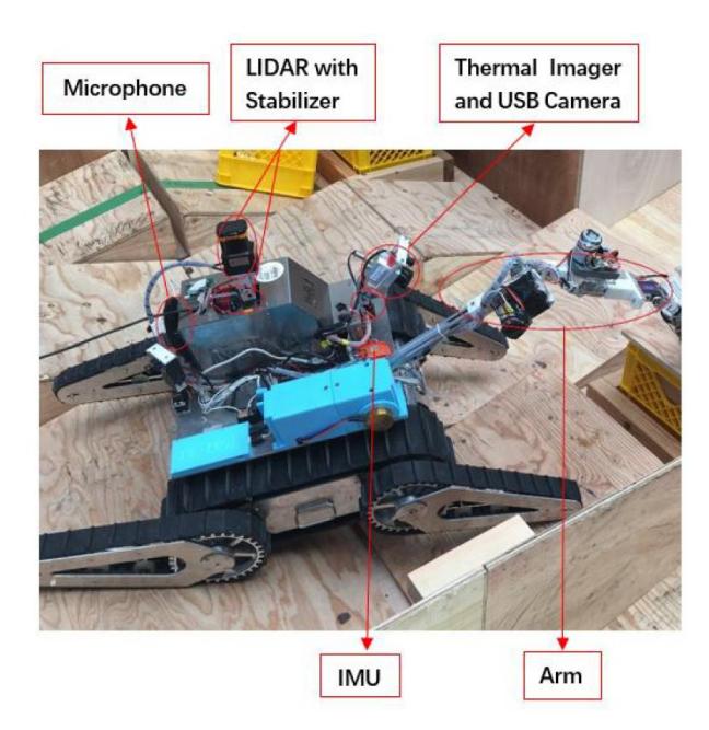
In this paper, we thoroughly describe how we designed and built our tracked rescue robot, which has not only a strong mobility, but also good dexterity and high intelligence. It has three section, six tracks and an arm which is shown in Figure 1. Based on the original power track, our robot focuses on improving the climbing ability of front and rear fins to make the robot platform more adaptive in the face of more dangerous terrain with oversize obstacles. The arm is used to accomplish dexterity tasks such as grasping, unscrewing, stamping, etc. Moreover, the camera mounted on the robot arm helps the operator to see some blind spots in the field of view.
For the perception part, our robot has a 2D Hokuyo Laser scanner, inertial measurement unit, microphone, USB-cameras and other extensions accessories. By sending back the realtime image information of on-board cameras, the operator can remotely control the robot go through the complex disaster environments. At the same time, our robot can also create the map of the environment, detect victims and recognize the hazmats.
As the rescue missions become more and more complex, it is vital for our robot to realize a higher intelligence. We have added some semi-autonomous functions to the robot, such as robotic arm semi-autonomous motion planning, waypoint semi-autonomous navigation and flipper-based semiautonomous exploration. Our lab focus on rescue robot research for eight years and based on our rescue robot, we have conducted some research [1], [2], [3], [4], [5].
NuBot rescue team is supported by Robotics Lab, Department of Automatic Control at National University of Defense Technology (NUDT).
II. SYSTEM DESCRIPTION
Many impressive results about the design of the robot system for USAR missions have been achieved, and various robots have been developed for USAR tasks. In early years, rescue robots were usually teleoperated by human operators. With robotic technology advances significantly, the robots autonomy level has been improved greatly. In order to adapt to the actual rescue environment, we also designed our rescue robot system to realize teleoperated operation, semiautonomous and fully autonomous operation [3].
A. Hardware
Our robot uses a tracked platform, as shown in Fig. 1. The tracked robot with front and back sub-tracks (flippers) provides effective mobility, and it is the mostly common platform used in the RoboCup RRL competitions and also in the real rescue missions.
In order to complete the USAR missions, the mobile robot must be equipped with an onboard computer and various sensors for mapping, navigation and victim detection.
The robot uses a state-of-the-art industrial grade computer from Beckoff. The computer (Intel Core i7) provides enough processing ability to deal with huge data and the robustness when traversing challenging terrains.
The robot is equipped with a Hokuyo UTM-30LX Light Detection And Ranging (LiDAR). The LiDAR is suitable for mobile robots because of its low power consumption and compact size. The field of view of the scanner is 270°, the scanning distance is 30m and the scanning frequency is 40Hz. Hokuyo UTM-30LX can be used for distance measurement, and the quality of the acquired data is almost the same on different surfaces, colors and even under different illumination.
In order to measure the robots pose when exploring in the unstructured and uneven terrains, a 6DOF inertial sensor, Xsens MTI-100 has been integrated. MTI-100 is a miniature Inertial Measurement Unit (IMU) that outputs yaw angle with no drift, and provides a calibrated three-axis acceleration, angular velocity and magnetic field strength.
Visual perception is the most important source for victim detection. Therefore a pan-tilt-zoom camera is mounted on the tracked platform. Besides, a low-cost USB video camera and a Thermal Image Optris PI640 has been employed. The visual sensors are fused to detect and localize victims.
In addition, the robot is equipped with a multiple-degreeof-freedom arm. In the rescue environment, the arm can open the door, open or close the valve and delivery goods to victims or other operations.
B. ROS-based Software
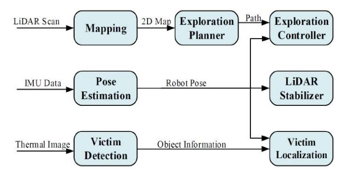
Robot Operation System (ROS) is used to build the software of our rescue robot. It is the most popular robotic framework nowadays. It provides open source tools, libraries, and drivers for robotics researches and applications. ROS enables researchers to quickly and easily conduct experiments. The software architecture of our rescue robot is shown in Fig. 2.
III. 2D SLAM WITH ACTIVE LIDAR STABILIZER
A. 2D SLAM
The ability to build a map of the unknown environment and localize itself, named as SLAM, is one of the most important abilities for robots to operate fully autonomously in USAR scenarios. Most existing 2D SLAM algorithms are based on probabilistic representations. The advantage is the robustness to measurement noises and the capability to formally represent uncertainty in the measurement and estimation process. Furthermore, most probabilistic SLAM algorithms are built upon the Bayes rule.
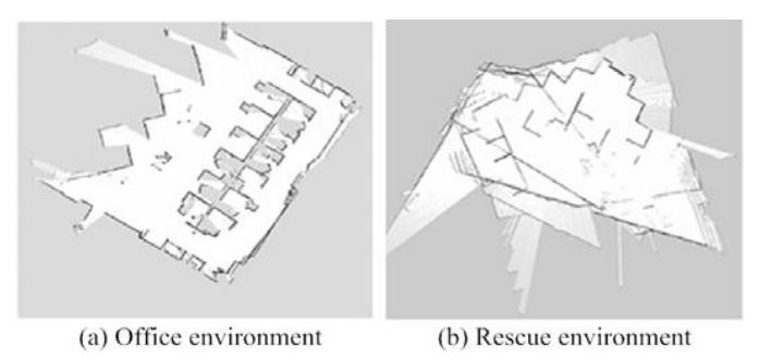
HectorSLAM [6] and Gmapping [7] are two typical Bayes based methods, and their open source implementations are available as ROS packages. HectorSLAM is a 2D SLAM system based on robust scan matching, while Gmapping use both odometry and scan matching. However, in the rescue environment, the odometry is unreliable, which makes Gmapping inapplicable. So we choose HectorSLAM as the basal SLAM system. HectorSLAM can perform well in a flat office environment (Fig. 3(a)), but there are many limitations if we use the HectorSLAM directly in the rescue environment (Fig. 3(b)). We will introduce how to deal with this problem in the next subsection.
B. Active LiDAR Adjustment
Robots for USAR are usually used in unstructured environments with uneven terrains. Therefore the sensor data might be spurious if the sensors are rigidly coupled to the robot. The challenge of uneven terrains has been added into the RoboCup rescue competition by using 10 and 15 pitch/roll ramps.
One way to overcome these problems is to use a 3D LiDAR instead of a 2D LiDAR. The registration of the 3D scans would build a exact global map, and the pose of the robot can also be calculated. However, it spends much more time to do the 3D scan registration with the global map than the scanning and matching in 2D.
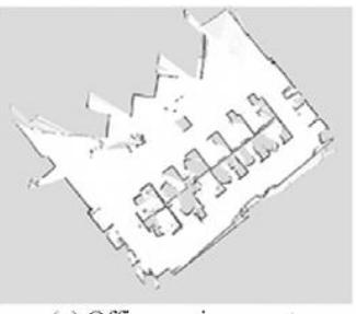
As a compromise, we have designed a cheap stabilizer with two servos to adjust the orientation of the 2D LiDAR, based on the readings from the MTI sensor. As a result, the 2D LiDAR can be kept on the horizontal plane even when the robot is traversing on uneven terrains. The rotation/tilt stabilizer unit mounted on the robot is shown in Fig. 1. The result of HectorSLAM with LiDAR Stabilizer is shown in Fig. 4.
IV. AUTONOMOUS EXPLORATION
A fully autonomous USAR robot must explore the rescue environment and search victims autonomously. This problem can be separated into three questions:
- Selecting a target point: Where should the robot go next?
- Planning a path: Which way should the robot take to go to the target?
- Computing the control command: What action should the robot do?
A. Frontier-based Exploration
The primary problem of autonomous exploration is: based on existing knowledge about the real world, where should the robot move to efficiently acquire new information?
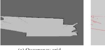
Most approach use the occupancy grid. When a grid map has been built, all the grid can be divided into three categories: Free, Unknown and Occupied. The primary idea is as follows: in order to get new information, going to a frontier which separates known regions from unknown regions. The frontier here is a cell in the occupancy grid which is marked as free but has a neighboring unknown cell. A segment of adjacent frontiers is considered as a potential target if it is large enough for the robot getting though. If more than one potential target are detected, the closest one is selected. Figure 5 shows the result of extracted frontiers.
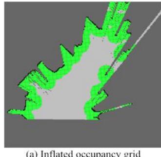
A disadvantage of directly extracting frontier from the original map is that the extracted frontier may be close to obstacles. To overcome this problem, the Inflated Obstacle method has been utilized. This method will transform the cells within a certain distance to obstacles as Occupied, thus the frontiers will not be extracted in these areas. Figure 6 shows the result of extracted frontiers in the occupancy grid with inflated obstacles.
Unknown areas could be occupied or free areas, which have not been known by robots. In the narrow rescue environment, the probability of the unknown areas being obstacles is quite high. Furthermore, the computational complexity of path planning will increase as the scale of the built map, so the frequency of path planning will not be high for autonomous UASR robots. If the robot takes one frontier as the target point, and the frequency of path planning is low, or the robots moving distance to the target is small, the robot may crash with unknown obstacles.
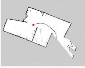
Figure 7 shows such a example where the robot may be stuck. The red point represents the robots position, and the black curve represents the planned path. In this situation, because of the low frequency of path planning, the robot will not re-plan the path before arriving the target point, so the robot may crash with obstacles. The worst result is that the robot can not move any more.
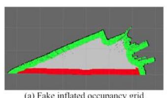
To deal with this problem, we proposed a method named as Fake Inflated Obstacle, where those extracted frontiers located between free areas and unknown areas are considered as obstacles, then these obstacles are inflated, and finally new frontiers can be searched between these inflated areas and free areas. Using this method, the distances between the target point and the actual obstacles are enough for our robots safe movement. The extracted frontiers from fake inflated obstacles are shown in Fig. 8.
B. Path Planning and Controller
When a target has been selected by the frontier-based method, the problem turns into optimal path planning. Following Javis and Byrne [8], we proposed the distance transform to find the closest way from an arbitrary starting point to a fixed target. The distance transform of an occupancy grid calculates the cost to reach the target cell for each free cell. The cost between two cells (without obstacles between them) can be the chessboard distance, city block distance, or the Euclidian distance. After the distance transform has been applied for each cell of the grid, the shortest path from any cell to the target cell can be searched simply by following the steepest gradient.
Based on the SLAM and exploration planning algorithms mentioned above, the robot can build the 2D grid map and plan a path to the next frontier. Ideally, the robot can explore the environment autonomously after integrating a simple controller to compute the commands to drive itself. However, different from virtual simulation environment or ideally indoor scenarios, real disaster sites are filled with unstructured terrains. Coupled with the inaccuracy of tracked vehicles, it is quite challenging to realize accurate control of the robot to follow the exploration path. A simple controller, which directly produces the velocity command by calculating the biases of current position and orientation of the robot with the target, can not perform well in real world experiments. Therefore, we propose a novel controller combining the exploration planer and multi-sensor information to overcome the influence of challenging terrains. The inputs of the controller are LiDAR data, IMU data, the current position and orientation of the robot and the target.
The experimental results show that using this kind of multi-sensor based controller, the exploration efficiency and robustness can be improved, and the robot can explore the full rescue environment of the 2018 RoboCup China Open RRL competition, as shown in the video posted on our website.
V. SEMI-AUTONOMOUS EXPLORATION
In order to adapt the actual rescue environment and make the operator easy to accomplish the USAR missions, we have added some semi-autonomous functions to the robot.
MoveIt integrates some modules for arm motion planning with collision detection. These modules exist in the form of plugins, which make MoveIt easier to expand and can communicate with different libraries at the same time. Based on MoveIt, we set up a semi-autonomous function, by which we only need to set the target position of the robots hand or a given trajectory for the robots hand, and it can autonomously generate a trajectory of the robots arm while avoiding obstacles. Once we confirm the trajectory and request an action, the robots arm can autonomously track the planned trajectory.
We have also developed the way-point navigation. We collect way points during the run phase, and use these way points to realize semi-autonomous navigation when the operation way of the robot is switched to semi-autonomous. We use the timed elastic band (TEB) approach to quickly reach the way points. The TEB method takes the state of the robot and the time of the adjacent state as the optimized node. Constraints between the states, such as velocity, acceleration, and nonholonomic constraints, are used as the optimized edges.
Another semi-autonomous function we have implemented is flipper-based semi-autonomous exploration, using robotic inertial sensors and flippers. According to the different postures of the robot during the movement, the flipper-based semi-autonomous exploration algorithm automatically adjusts the flipper to keep the robot in a safe posture. This semiautonomous free the operator from the operation of the robot's flippers during the entire mission and simplifies the complexity of the operation.
VI. VICTIM DETECTION AND LOCALIZATION
Reliable detection of human victims in unstructured post-disaster environments is a key issue for USAR robots, which is challenging in the rescue environment with low illumination, dust and smoke when using normal visible light camera. Therefore we use a thermal camera (Optris P640) to recognize the simulated victims autonomously using a blob detection algorithm. After segmenting the thermal image with a threshold like 36°, the connected warm regions can be regarded as victims.
After detecting the victim successfully, the position of the victim should be estimated on the built map. The image coordinate of the victim can be used to evaluate the victims direction in the camera coordinate system. Because the victim should be located on the obstacles, using the victims direction and the cameras orientation, the victims position can be estimated by searching the nearest obstacle on the built map along the victims direction.
VII. APPLICATION RESULTS
The RoboCup RRL competition provides a systematic benchmark for testing and evaluating teleoperated and autonomous USAR robots in a simulated post-disaster environment. We present the results achieved when participating the RoboCup China Open 2016. In this competition we won the championship based on exploring the rescue environment autonomously.
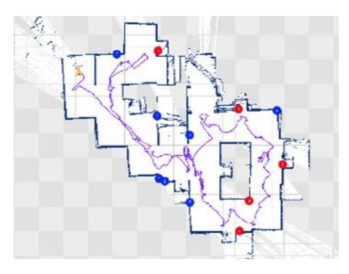
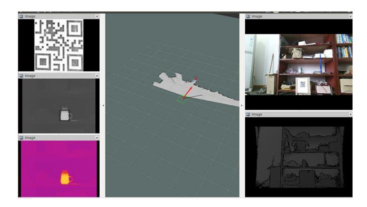
Figure 9 shows the map of explored arena and the marking of the found victims and recognized QR-codes on the map (Fig. 10). It should be noted that the robot successfully found 5 victims autonomously and the total number of victims was 8 in the final competition. The number of the recognized QR-codes correlates with the fraction of the arena that was explored by the robot during the competition. Videos of the final competition and experiments are available on our website.
VIII. CONCLUSION
Our rescue robot can achieve good performances in both telecontrolled and autonomous modes. Currently, we are going to participate in the 2019 RoboCup ChinaOpen, which will be held from 17th April to 21th April in Shaoxing, Zhejiang province, China. RoboCup ChinaOpen will provide a chance for us to prepare and improve our robot system for participating the RoboCup 2019 in Sydney, Australia.
APPENDIX A TEAM MEMBERS AND THEIR CONTRIBUTIONS
Currently, there are three supervisors and five team members in the NuBot. The supervisors are Hui Zhang, Huimin Lu, Junhao Xiao. The team members are as follows:
• Chenghao Shi Mechanical Design, SLAM algorithm. • Shanshan Zhu Software System. • Chuang Cheng Autonomous Exploration. • Wenbang Deng Mechanical Design, Controller. • Xieyuanli Chen Software System.
APPENDIX B CAD DRAWINGS
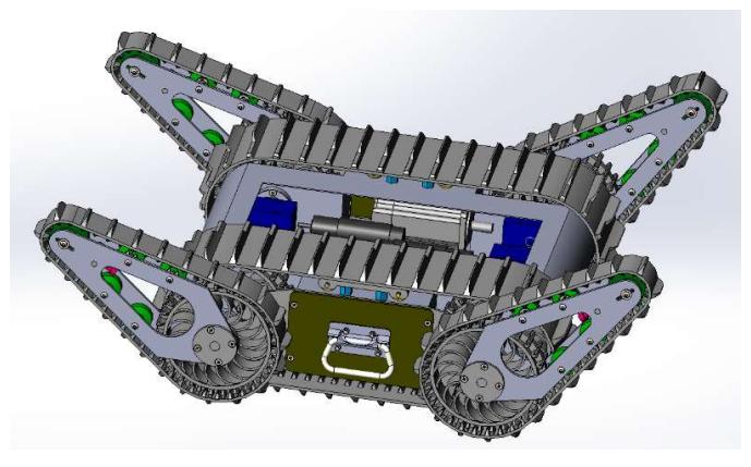
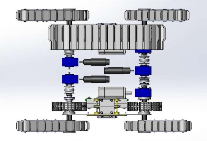
The mechanical structure of the robot platform is shown in Fig 11. and Fig. 12.
APPENDIX C LISTS
A. Systems List
We list the Manipulation System in Table I. and the Software System in Table II.
TABLE I MANIPULATION SYSTEM
| Attribute | Value |
|---|---|
| Name | NuBot |
| Locomotion | tracked |
| System Weight | 28.41kg |
| Typical operation size | 0.6 x 0.6 x 0.5 m |
| Unpack and assembly time | 60 min |
| Startup time (off to full operation) | 5 min |
| Power consumption (idle/ typical/ max) | 60 / 200 / 800 W |
| Battery endurance (idle/ normal/ heavy load) | 120 / 60 / 30 min |
| Maximum speed (flat/ outdoor/ rubble pile) | 2 / 1 / - m/s |
| Payload (typical, maximum) | 50/ 100 kg |
| Arm: maximum operation height | 170 cm |
| Arm: payload at full extend | 1kg |
| Support: set of bat. chargers total weight | 2.8kg |
| Support: set of bat. chargers power | 220W (12-24V AC) |
| Support: Charge time batteries (80%/ 100%) | 30 / 60 min |
TABLE II SOFTWARE LIST
| Name | Version | License | Usage |
|---|---|---|---|
| Ubuntu | 14.04 | open | |
| ROS | indigo | BSD | |
| OpenCV-ORB | 2.4.8 | BSD | Haar: Victim detection |
| Hector SLAM | 0.3.4 | BSD | 2D SLAM |
| NuBot Exploration | 1.0 | closed source Autonomous Exploration |
ACKNOWLEDGMENT
The authors would like to thank the senior team members Pan Wang, Yi Li, Qihang Qiu and Ruoyi Yan for their great contributions to the NuBot rescue team. They have obtained their Master degrees and left the team. Our team is also supported by projects of National Science Foundation of China (No. 61403409 and No. 61503401).
References
[1] X. Chen, H. Zhang, H. Lu, J. Xiao, Q. Qiu, and Y. Li, "Robust slam system based on monocular vision and lidar for robotic urban search and rescue," in IEEE International Symposium on Safety, Security and Rescue Robotics (SSRR), Oct 2017, pp. 41–47. [2] X. Chen, H. Lu, J. Xiao, H. Zhang, and P. Wang, "Robust relocalization based on active loop closure for real-time monocular slam," in International Conference on Computer Vision Systems. Springer, 2017, pp. 131–143. [3] Y. Liu, Y. Zhong, X. Chen, P. Wang, H. Lu, J. Xiao, and H. Zhang, "The design of a fully autonomous robot system for urban search and rescue," in IEEE International Conference on Information and Automation, 2016. [4] P. Wang, J. Xiao, H. Lu, H. Zhang, R. Yan, and S. Hong, "A novel human-robot interaction system based on 3d mapping and virtual reality," pp. 5888–5894, 2017. [5] Q. Qiu, X. Chen, Z. Zeng, J. Xiao, and H. Zhang, "Target-based robot autonomous exploration in rescue environments," in International Conference on Information and Automation, 2018, pp. 609–614. [6] S. Kohlbrecher, J. Meyer, O. von Stryk, and U. Klingauf, "A flexible and scalable slam system with full 3d motion estimation," in Proc. IEEE International Symposium on Safety, Security and Rescue Robotics (SSRR) IEEE, November 2011. [7] G. Grisetti, C. Stachniss, and W. Burgard, "Improved techniques for grid mapping with rao-blackwellized particle filters," Robotics IEEE Transactions on, vol. 23, no. 1, pp. 34–46, 2007. [8] R. Jarvis and J. Byrne, "Robot navigation: Touching, seeing and knowing," in Proceedings of the 1st Australian Conference on Artificial Intelligence, vol. 69, 1986. [9] R. Lienhart and J. Maydt, "An extended set of haar-like features for rapid object detection," in Image Processing. 2002. Proceedings. 2002 International Conference on, vol. 1, 2002, pp. I–900–I–903 vol.1.