RoboCup Rescue 2019 Team Description Paper Red Knights
Paul Wichser, Peter Kirwin, Anne Dougherty
Benilde-St. Margaret's
Abstract This paper introduces a completely redesigned rescue robot, engineered by college preparatory students at Benilde St.-Margaret's secondary school. The Red Knights team has participated in the RoboCup Rescue competition since 2009 with iterations of the 2009 robot design, but this year, the team has decided to bring an entirely new design with more robust sensing capabilities as well as more sophisticated and intuitive interfaces including inverse kinematics that will allow the robot to better engage with dexterity tasks. The new robot will better traverse difficult terrain and navigate challenging obstacles in ways we have never attempted using independent flipper controls and sensor feedback. Improved navigation will use hardware and software solutions (addressed under the system description header) that allow 3D map making (for navigation) and victim detection.
Introduction
We believe that by designing an inexpensive machine, created out of commonly available materials we can improve access to lifesaving operations.
The Red Knights' ultimate goal for our robot is to explore disaster sites using autonomous and semi-autonomous functions. Our second goal is to make our robot easily replicable, cost effective, and transportable. We want the robot to be available to quickly and easily save lives wherever it's needed. We plan to achieve our second goal by using open source code and readily available technologies such as 3D printing, laser cutting, and CNC milling of internationally available materials so as to make replication and mass production reasonably feasible.
We will continue using a LIDAR mapping function. This will be useful for autonomous control. We will also be mounting sensors, cameras, microphones, and speakers to make semi-autonomous control simpler and to provide the driver a better understanding of the robot's environment.
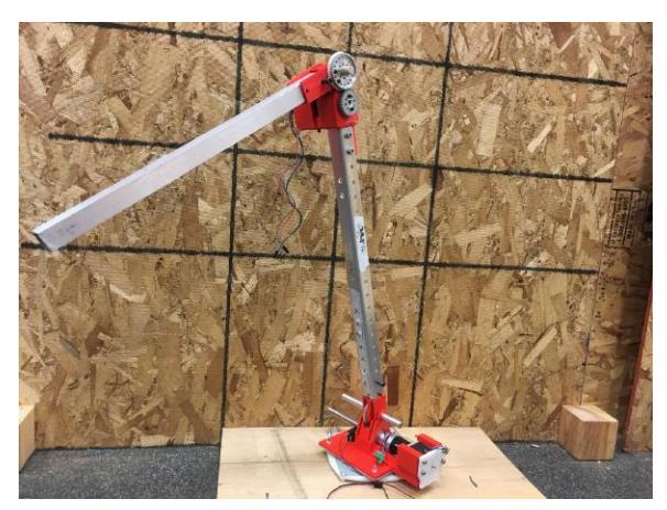
We have a dexterous arm that rotates, extends, and contracts by means of an elbow-joint swivel system, and uses an inverse kinematics system to make semi-autonomous control far more intuitive and efficient than single motor inputs. This, coupled with a grasper attached to its wrist with rotation and wrist-flexing abilities, allows our robot to perform tasks like opening doors, manipulating debris, and interacting with its environment.
System Description
(Section header only)
A. Hardware
(Section header only)
Locomotion
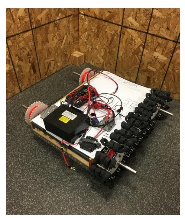
We are using two 24v Maxon drivetrain motors and two 12v worm gear motors in order to maximize our ability to move quickly and over rough terrain. There is one main drive train and two "flipper arms" with drive treads that will flip out from the main drivetrain to a) extend the drive train over a greater surface area, and b) enable the robot to climb up stairs and other surfaces by positioning the flipper arms so that the treads can apply sufficient force in a greater variety of situations. The treads are constructed from #41 k1 attachment chains and rubber LEGO tires in order to increase traction using repurposed materials. The main structure of the chassis is made of aluminium (though has been prototyped with plywood) with 3D printed and laser cut components. Image of the treds can be seen in the prototype release one photo above.
Manipulation
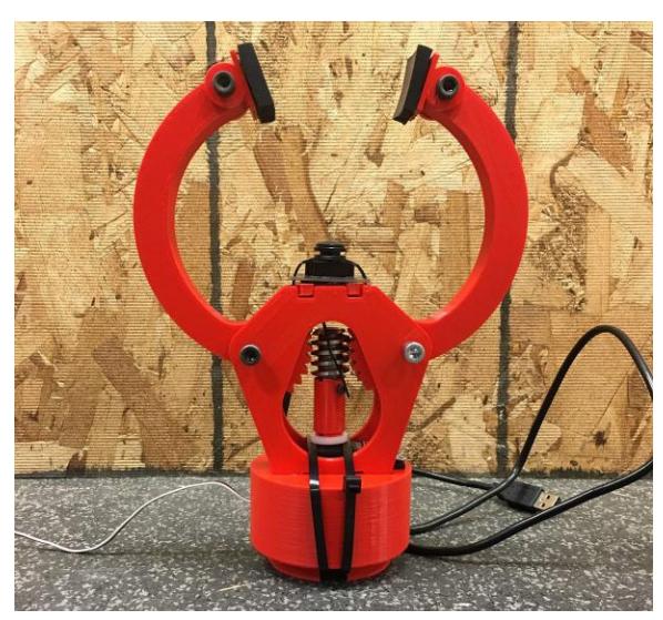
The robot utilizes a double-segmented arm on a rotating base in order to perform its dexterity and manipulation tasks. The arm is constructed from metal and 3D-printed components, and uses two stepper motors paired with potentiometers to accurately control the angle of each joint. It is 38" long at full extension. The grasper is constructed from 3D printed and laser cut components. It operates through a Parallax continuous rotation servo for opening and closing and a Parallax standard servo for wrist rotation. Altogether, our goal is to enable precision movement in the arm and wrist.
Power
We will be utilizing a LiFePO4 24v battery and 5v cell phone charging batteries to power the motors and computers respectively.
Sensing (Hardware Aspects)
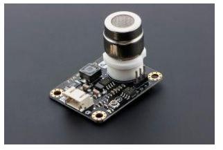
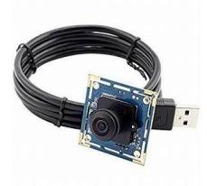
The robot will have a multitude of sensors to allow for multi-sensory detection of its environment. A DFRObot 0159 CO2 detector will be mounted on the robot's main body to detect respiratory outputs as a sign for life in the area. Three cameras, two regular and one thermal, will be mounted as well. The FLIR Lepton Thermal Camera 1.4 will allow for heat signature detection that could potentially be helpful while surveying for life, while the other Megapixel USB Cameras—one mounted to the grasper and the other to the body—will allow for more traditional image and environment viewing. Corner sensors measuring distance will be mounted to the robot as to avoid unwanted wall collision. An audio sensor will pick up sounds in the robot's vicinity.
Other Mechanisms
Micro-controllers, Raspberry Pi with a RoboPi hat, Talon Motor Controllers, stepper motor controllers, wifi router
B. Software
(Section header only)
Sensors (Software Aspects)
The potentiometers will be used to read the angle of the arm's joints and feed values to our inverse kinematics code to move the motors to their correct values. The camera will use image recognition to read signs and any other entities we deem needed for recognition.
Victim Detection
Victims will be detected through use of the DFRObot 0159 CO2 sensor. Once calibrated and a base reading is taken, the sensor will display any changes in CO2 level (detecting breath) by displaying a light and a reading a value on our display. The FLIR Lepton Thermal Camera 1.4 will also help with victim detection by detecting their heat signature.
Automation
We plan on using several semi-autonomous functions as to make the handling of our robot easier. The functions are the following:
- Inverse Kinematics: The robot takes Cartesian cubic inputs and converts them to motor angle outputs to move our robot's arm to a specific point in space. Motor angles are measured using potentiometers.
- IR Sensor-Based Object Avoidance: Using similar technology to self-driving cars, the robot will sense when it is driving towards a wall and automatically adjust itself to avoid collision. When driving directly towards a wall, the robot will read the distance between itself and the wall and stop before collision that could result in damage; when driving alongside a wall, the robot will automatically align itself so that it stays a fixed distance from the wall. This will be an assistive feature while using remote operation.
- Direct Motion Control: By moving a joint attached to a person's arm, a potentiometer send an output to the robot arm's motor to move. This allows for more fluid motion and more intuitive movement inputs.
- Dead Reckoning: The robot has a toggleable function that lets it record all inputs given for a set time. When activated, the dead reckoning function will "replay" inputs to generate those same outputs autonomously, allowing the robot to drive itself along a predetermined path indefinitely.
- Indoor "GPS": The robot uses a set of five "GPS" nodes, small machines which use sound to find the relative location of each other sensor.
Navigation
Tele-operative navigation is managed through visual data streamed through a website-based Raspberry Pi / RoboPi system. This system is compatible with standard network and Raspberry Pi cameras, which will provide us with edge, horizon and obstacle detection data as well as images. Cameras are mounted to move for better visual acuity. Smaller cameras will also be mounted in the grasper part of the robot for ease of use with the dexterity tasks. All data will be transmitted through a website interface.
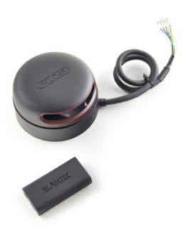
Aiding in navigation will be the Indoor "GPS", IR Sensor-Based Object Avoidance, Dead Reckoning, and LIDAR. LIDAR mapping systems provide us with a constantly updated layout of our surroundings using infrared radiation that creates a map for the robot to see its surroundings.
Arm Control
The arm will have multiple control schemes to provide choice and accessibility, based on need.
Basic keyboard inputs using keys W, A, S, D, Q, and E will be used interchangeably with a game console controller to adjust inverse kinematic values. A joint sensing sleeve can also be worn by the operator to directly drive the angles of the arm motors and provide intuitive arm control.
Spacial awareness will be provided by the camera in the grasper, other cameras on the body of the robot, and a 2D simulation of the arm joints in order to help visualize the space. The simulation is generated in pygame using the same math that determines the motor angles.
C. Communication
In addition to the previously mentioned cameras, the operator will be able to communicate through the robot via speakers and a microphone mounted on the robot. All communication between the robot and the operator is handled by a wifi router, and can be both tethered with CAT5 cable and untethered.
D. Control Interface
The robot is controlled via an operating bay consisting of a laptop, a game console controller, and an auxiliary screen displaying sensor data, cameras, motion detection, hazard label recognition, inverse kinematic display, and thermal camera video. The UI includes separate controls for locomotion, arm movement, sensor activation, camera movement, and various toggleable autonomous functions such as the Dead Reckoning system.
Application
(Section header only)
A. Set-up and Break-down
With the addition of an independent power source, setting up the Red Knights' operator station should be as simple as flipping a switch. The control console has an integrated WiFi router, antenna, control computer and monitors as well as a control device, so it is an all-in-one control console solution. Communication and application programs start automatically upon boot, saving time over computer boots where applications must be launched manually. Operator station break-down is simply shutting down the control console.
B. Mission Strategy
With an entirely new robot, our major strategic goals center around improved performance in maneuverability and mobility tasks with new use of autonomous multipliers. Because of our improvements in intuitive arm control, some dexterity tasks are considered to have high point potential for our team.
We will not be competing in the sand and gravel hills or stair debris.
C. Experimentation
As in previous years, we will be using a RoboCup Rescue test arena constructed in our lab. This year, however, we have added additional challenges in order to test mobility through the course and dexterity of the arm. This allows us to continually test and evaluate components of our robot. The classroom operates through Agile Learning and SMART goals which serve as a structure for our testing and development cycle. The school provides MacBook Airs which are available for all students to write and test code. We additionally have a number of smaller robots (kitbots) which are 3D printed in order to prototype designs and assist in program testing.
D. Field Application
One of our goals for this year is to increase our potential for field application and accessibility. This continues our trajectory of having a more inexpensive and capable robot. We feel that having a robot that can be constructed quickly and cost-effectively offsets any minor compromises to structural integrity. As the intended use of this robot is as a first responder, we want to concentrate on ensuring that our robot is accessible. Ultimately, we want our robot to be creatable and usable by the general public.
The robot will be easy to recreate and easy to control. We estimate a timeframe of under two weeks for full construction.
Conclusion
This paper serves to give a detailed outline of the Benilde St. Margaret's Red Knights team's work over the 2018-2019 season. It covers the aspirations of our team as well as the parts and designs used to achieve our desired results.
APPENDIX A
(Section header only)
Team Members and Contributions
Coaches: Paul Wichser Peter Kirwin Anne Dougherty
Traveling Student Team: Aaron Wachowiak Aidan Lee-Gilligan Aidan Luebke Amelia Backes Anna Kocourek Benjamin Barry Bradford Shibley Brian Meyer Connor Weatherly Declan Buggy Peter Lynch Isabel Fleming Jack Bruer Kalam Storrs Maria Rossman Maxwell Jensen Michael Miller Nathan Spurgat Nathan Parece Nicholas Carpenter Oriana Sampson Owen Knickelbine William Driessen William Valley
Other Contributions: Benilde St.-Margaret's graduating classes of 2019, 2020, and 2021
APPENDIX B
CAD Drawings Under development
Table I Manipulation System
| Attribute | Value |
|---|---|
| Name | Red Knights |
| Locomotion | Treads |
| System Weight | TBD |
| Weight including transportation case | TBD |
| Transportation size | 4ft x 2ft x 2ft |
| Typical operation size | 4ft x 2ft x 4ft |
| Unpacking and assembly time | 120 min |
| Startup time (off to full operation) | 5 min |
| Power consumption (idle/ typical/ max) | 17.6A |
| Battery endurance (idle/typical/heavy load) | 30 min /20 min /10 min |
| Max speed (flat/ outdoor/ rubble pile) | 25 /20/?mph |
| Payload (typical, maximum) | TBD |
| Arm: typical operation height | 2ft |
| Arm: payload at full extend | 5ft |
| Support: set of bat. chargers total weight | 4 lbs |
| Support: set of bat. chargers power | 24 lbs |
| Support: charge time batteries (80%/ 100%) | 7 hrs |
| Support: additional set of batteries weight | TBD |
| Any other interesting attribute | TBD |
| Cost | 2000 USD |
Table II Operator Station
| Attribute | Value |
|---|---|
| Name | Red Knights |
| System Weight | 2.38 lbs |
| Weight including transportation case | 3.30 lbs |
| Transportation size | 13in x8in x2in |
| Typical operation size | TBD |
| Unpack and assembly time | 5 min |
| Startup time (off to full operation) | TBD |
| Power consumption (idle/ normal/ max) | TBD |
| Battery endurance (idle/ normal/ heavy load) | TBD |
| Any other interesting attribute | TBD |
| Cost | 3000 USD |
Table VI Hardware Components List
| Part | Brand & Model | Unit Price | Num |
|---|---|---|---|
| Computer | MacBook Air | 1200 USD | 1 |
| Monitors | |||
| External | Router | 150 USD | 1 |
| Controllers | |||
| Power Supply | 250 USD | 1 | |
| Backup Battery | DuraComm | 150 USD | 1 |
| Mounting Stand | 400 USD | 1 | |
| Axels | 30 USD | 4 | |
| Acetyl Plates | 150 USD | ||
| Printed Parts | Custom Made | 200 USD | |
| Fasteners | 100 USD | ||
| Router | 126 USD | 2 | |
| LIDAR Scanner | RPLIDAR A2M8 360º Laser Scanner | 320 USD | 1 |
| IR Range Finder | Sharp GP2D12 | 26 USD | 2 |
| MiniIMU | Pololu | 20 USD | 1 |
| MicroComputer | RaspberryPi RoboPi Controller | 100 USD | 1 |
| 35 USD | 1 | ||
| CO2 Sensor | Heimann | 25 USD | 1 |
| Thermal Camera | FLIR Lepton Thermal Camera 1.4 | 7.99 USD | 1 |
| Camera | Megapixel USB Camera | 39.99 USD | 1 |
| 46 USD | 2 | ||
| Motors | CIM | 56 USD | 2 |
| Wheels | 50 USD | 2 | |
| Belting | Tslibaki RS41 Roller Chain | 4 | |
| Motor | Maxon motor RE65 353295 + gear GP81 110412 | 822 USD | 4 |
| Controller | Talon SR Motor Controller | 90 USD | 1 |
| Reducer | 24-12v reducer Board | 18 USD | 2 |
| 35 USD | 2 | ||
| Batteries | LiFePO4 Batteries | 240 USD | 2 |
| Wiring | 20 USD | ? | |
| Robotic arm | HSR-5980SG Servo Motors | 110 USD | 2 |
| Servo Motors | |||
| Analog devices | AD5241 Digital Potentiometer | 3 USD | 1 |
Table V Software list
| Name | Version | License | Usage |
|---|---|---|---|
| Web2Pi | Python 2.7 | 1 | |
| Pygame | 1.9.4 | open | 1 |
| RoboPi Library | Python 2.7 | 1 | |
| ImRec software | BSD | 1 | |
| Lidar software | 1 |
References
(No references section provided in the source material)