RoboCup Rescue 2019 Team Description Paper X-kau ITNL
Daniel Pescador, Abel Avalos, Francisco Perez, Lourdes Bolanos, Jacobo Hernandez, Daniel Cruz, Dante Barboza, Laura Gomez-Sanchez, Juan-Angel Rodriguez, Marco Ramirez-Sosa, Dulce Martinez-Peon
ITNL
https://itnl.edu.mx · https://to.be.announced.org
Abstract In this work we describe the characteristics of our robot, the paper describes the entire work that until now we have. The main work for this year comes from the feedback by the State Civil Defense, which helped us to redesign the robot and to think how to tacled the problems for the most commons incidents. We present the learned lessons and the design focused for rescue tasks.
INTRODUCTION
I N the last 20 years the frequency of natural disasters has increased according to the disaster statistics of the UNIDSR (United Nations Office for Disaster Risk Reduction) and their impact on populated cities or cities with a lack of access is higher. There are also many risks involved in the rescue operations, during and after a disaster, not only for the victims but also for the rescue teams. To reduce those possible risks for victims and rescue teams, advanced inspection and location technology is needed. The aim of this project is to create such mobile technology capable of helping rescue teams to inspect the disaster area to make a risk evaluation on locating and rescuing possible victims during the rescue operations.
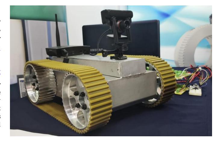
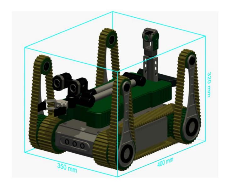
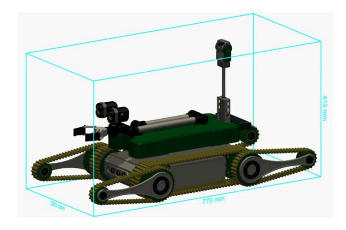
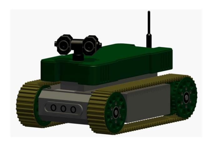
X-kau team was created in 2017, after the last significant earthquake that shaked Mexico City and some neighbouring States leaving dozens of people killed and wounded. In 2018, in the Mexican State of Nuevo Leon, a mall under construction fell with workers inside of the building killing five of them. These incidents motivated our team to create better robotic systems to help in this kind of disasters. We decided to go to the entity responsible for rescuing civilians from natural disasters in our country, the State Civil Defense. They helped us by providing us the statistics of the most common disasters in our region. Among the main tasks of the State Civil Defense Office of Nuevo Leon has, include the rescue of children that get caught up in small holes and old wells. For that reason this year we decided to manufacture a smaller robot, configurable and arranged. Thus is, a modular reconfiguring robotic system, in such a way that it can be a simple mobile robot, see Fig. 1, with flippers, both configurations with and without a robotic arm, see Fig. 2. In addition with the mobile robot structure sensors, the sensors in the arm can provide a video image of the vision of the robot. However, it is impossible to have a unique system for all the rescue work, but at least we expect to have a system that could cover as much as possible.
In the robotics laboratory of the ITNL, where the project has been taking, it is growing a new generation of students that are concern about solving problems where the robotics can help. At the same time, they know that the real problems have dynamics, constrains, undesirable noise, delays, unknown environments and they know that they need advanced strategies to tackled them. In that sense, X-kau team is searching to solving each one of this problems and, while this is being resolved, it is proposed to train students to apply the knowledge of advanced robotics and, at the same time, apply these acquaintance to solve problems to navigate, collaborate and send information in a disaster environment. The implemented solutions and the solutions in developing are thought in the problem of searching victims in the shortest possible time, monitoring the state of victims and to be able to evaluate the possibility to improve their conditions during the rescue operation, provided the rescue operation is indeed possible. All the mobile robots are builded by the students.The description of the system is detailed below.
Improvements over Previous Contributions
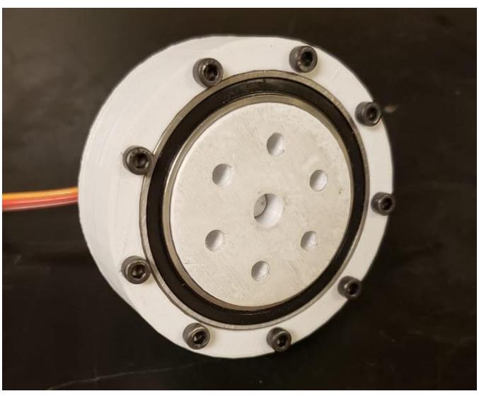
The main difference from last year's Robocup Rescue competition robotic design, is that in the current design takes in consideration specific features defined by the State Civil Defense Office of Nuevo Leon, which in their opinion will increase their efficiency on locating and rescuing victims in local or regional common disasters. From those needs a new structural design is proposed having a modular construction, smaller size and lighter weight than last year's prototype. It was shown from our previous competition that the polymeric caterpillar tracks were highly efficient on all terrain locomotion, however the nature of the handcrafted construction of our prototype made very complex the modelling and motion planning tasks. Furthermore, an specific location of all circuitry was not considered in the structural design and analysis, now having a better knowledge of all electronic equipment needed to be carried by the structure, their needed area, volume and best possible location, we have created a structural design considering the the most suitable location and space for each piece of electronic equipment from the start. Another problem we had in previous design was the motor selection, based on a very low budget, resulted in a very poor overall performance. Another improvement, in the current design, is that instead of using commercial motor gears now we are using our own motor gears, designed and constructed by the members of team using the facilities of the Robotics Laboratory in our University. Such new motor gear design, see Fig. 9 and local construction reduced building costs, weight, dimensions and motor efficiency.
SYSTEM DESCRIPTION
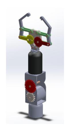
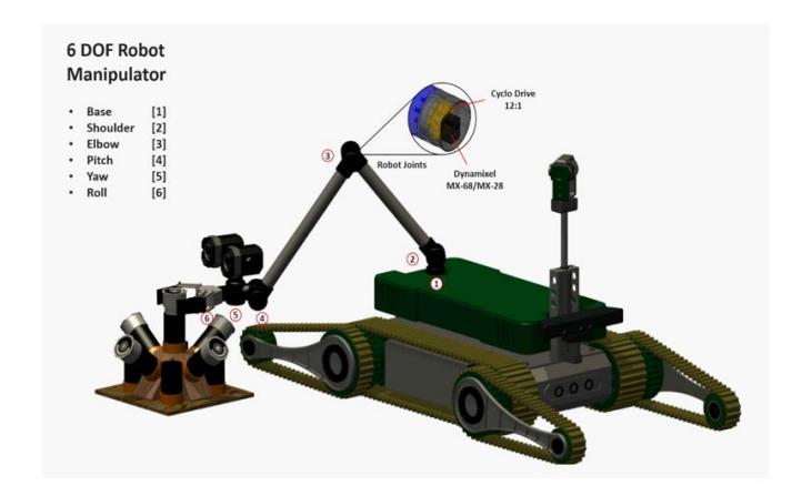
The proposed design of the mobile robot is capable of having 3D complex terrain access, such as climbing irregular surfaces or going up and down stairs. The modular design of its motion elements makes easier to find a solution to the trajectory planning. Furthermore the mobile robot has a pan a tilt camera in rear of the chassis of the platform and installed in the front of the chassis, a 6 DOF arm which can be used to have a better access to crevices in walls or surfaces to improve the reach of the inspection space for the platform; the arm also has a two-finger-gripper capable of manipulating small objects (less than 1kg). The 6 DOF arm has 3 electric cylinders as linear actuators in the first three joints from the base, and the last three actuators are highly efficient motors, having each an independent H bridge controller for each motor.
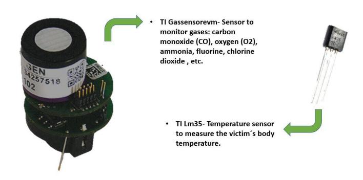
Sensors installed in the platform are to monitor the existence of a certain concentration of gases such as: Carbon Monoxide (CO), fluorine (F), Chlorine (CL) and Carbon Dioxide (CO2). The other sensor is a thermal camera installed in the arm structure and it is needed to detect temperatures close to possible body temperature of victims.
Although the proposed design is teleoperated, it has an automatic cinematic controller to regulate position and velocity. The motion of the robot as a crawler robot is based on polymeric caterpillar tracks, which adapt to several types of surfaces. For more complex motions flippers are added to modify its configuration of motion and geometry depending on the use, coordination and trajectory planning of each flipper.
All data acquired by sensors and cameras will be preprocessed and transmitted to teleoperators by a mini computer installed in the chassis of the platform. The weight of the computer is about 0.3 kg, using as OS, Ubuntu 16.04. Most of the main information processing tasks are performed by this computer, tasks such as control, location, mapping and image reconstruction, and its local communication is done using a Xbee kit.
All processed information and raw data from sensors and cameras, displayed in a proposed HMI will serve as an interaction tool between the robot and the operator.
Hardware
The information of the Hardward is in the Tables I, II and III in the Appendix.
- Locomotion: The robot as it is shown in Fig. 2, has a weight of 8 kg. 0.4 m long 0.3 m wide and 0.25 m high. With all the modules equipped as are being shown in image 2, has a 15 kg weight. 0.4 m long 0.35 m wide and 0.32 m high. The robot is based in the modular concept with a central module which is connected toward additional modules, the modules that we work with on this robot are: flippers, manipulator, monitoring tower and robot's head.
- Main module: Is a tracked with caterpillars mobile robot, the main module objective is to provide basic capabilities to the robot such as movement, to communicate with the operating station and deliver electrical power for other modules that are required in order to operate.
- Flippers: is possible to connect up to two pairs of flippers in the mobile base of the main module, 2 in the frontside and 2 in the backside, the flippers allow to adapt and balance properly in the land where the robot moves, each Flipper has independent movement, and canalso rotate 360 degrees in both directions, for their application in land it's possible to controll the flippers in a manual mode (moving each flipper with the command control) or automatical mode (the fippers with the equipped sensors in the mobile base are able to adapt in different obstacles such as stairs, ramps and inclinated slopes) as is required by the operator needings.
- Monitoring tower: is a retractable tower equipped with a pan-tilt camera that allows to know the status of the robot and its position in the environment. It's possible to remove the monitoring tower in order to use the robot in confined spaces where this action is required.
- Manipulator: is possible to equip to the main module with a 6 DOF manipulator as it ishown in figure number 3, the manipulator is equipped with an end effector that can be interchangeable and also has a CO2 sensor mounted on the end effector.
- Robot head: equipped with RGB camera, Infrared camera, led lamp, speakers and microphones to get a correct victims detection and establish communication with them. All these is due to the recommendations of rescue groups in Nuevo Leon, Mexico. The team pretends to continue working on the development of Reconfigurable Modular Rescue Robots. The most important team thought is to be a main tool on rescue operations.
- Power (Batteries): the system has three batteries at 5V 2.1A, the main consumption is the mini PC, the robot arm and the mobile robot.
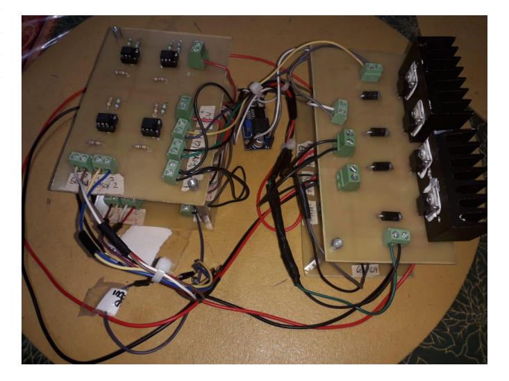
- Electronics: the motors are controlled by two H bridge each one, see Fig. 5.
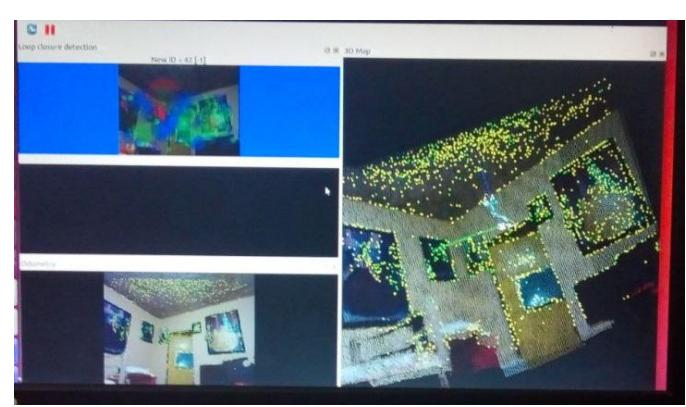
- Sensors: the system has 2 sensors, see Figure 12. One of them, a sensor to monitor gases: carbon monoxide (CO), oxygen (O₂), fluorine, chlorine and dioxide, this sensor is mounted in the body of the mobile robot. The other sensor is a temperature sensor, the goal of this sensor is to measure the victim's body temperature; this sensor is mounted in the robot arm. A camera is mounted in the robot arm, and their function is to send information to a mini computer (mounted over the mobile robot) to mapping the environment, see Figure 11.
- Computation: the system has a mini PC mounted in the body of the mobile robot. It has a weight of 0.3 kg. The OS is Ubuntu 16.04. All the main processes (control, mapping and reconstruction) are carried out here.
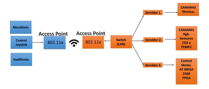
- Communication: the Fig. 3 shows the communication structure between the robot and teleoperation station.
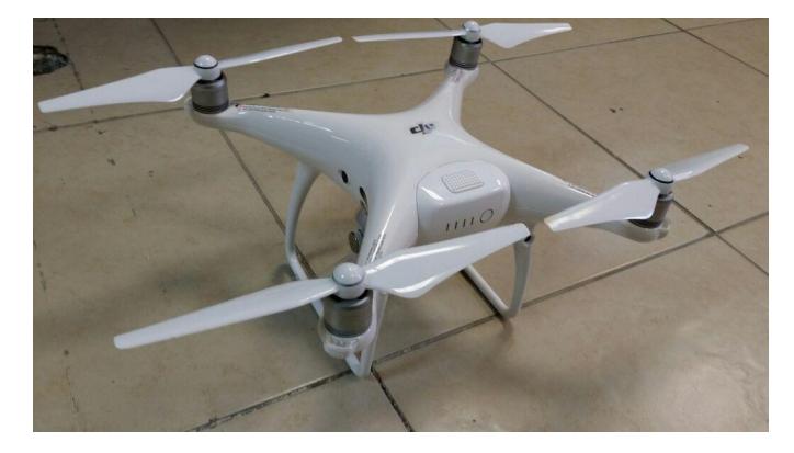
- Quadricopter: for aerial monitor a phantom (19S) is used, see Table II for the characteristics of the phantom. The goal of the 19S robot is to take pictures of the environment and to send this information to the Iktan Robot. The mapping of the top area is reconstructed in the mini PC.
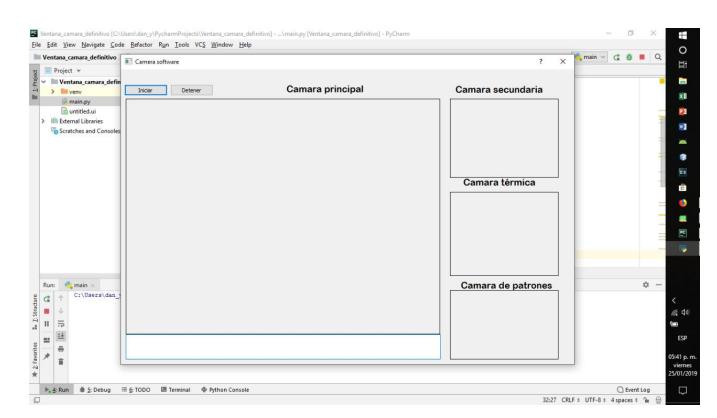
- Interface: to teleoperate the robot we design a GUI that allows to see the image of each camera, 3.
MANIPULATION SYSTEM
| Attribute | Value |
|---|---|
| Name | K'eeX |
| Locomotion | Tracked |
| System Weight | 15 kg |
| Weight including transportation case | 20 kg |
| Transportation size | 0.4 x 0.4 x 0.4 m |
| Typical operation size | 0.4 x 0.32 x 0.35 m |
| Unpack and assembly time | 60 min |
| Startup time (off to full operation) | 10 min |
| Power consumption (idle/ typical/ max) | ND |
| Battery endurance (idle/ normal/ heavy load) | ND |
| Payload (typical, maximum) | ND |
| Arm: maximum operation height | 0.8 m |
| Arm: payload at full extend | 1.5kg |
| Cost | 4000 USD |
AERIAL VEHICLE
| Attribute | Value |
|---|---|
| Name | 19S phantom |
| Locomotion | quadcopter |
| System Weight | 1.388kg |
| Weight including transportation case | 2.5kg |
| Transportation size | 22.5cm x 39cm x 33cm |
| Typical operation size | 50cm x 50cm x 20cm m |
| Unpack and assembly time | 5 min |
| Startup time (off to full operation) | 2 min |
| Power consumption (idle/ typical/ max) | 100 / 150 / 100 W |
| Battery endurance (idle/ normal/ heavy load) | 30 / 20 / 15 min |
| Maximum speed | 20 m/s |
| Payload | 0.15 kg |
| Any other interesting attribute | ? |
| Cost | 2000 USD |
OPERATOR STATION
| Attribute | Value |
|---|---|
| Name | Eliseo |
| System Weight | 13kg |
| Weight including transportation case | 5kg |
| Transportation size | 0.6 x 0.6 x 0.6 m |
| Typical operation size | 0.4 x 0.4 x 0.4 m |
| Unpack and assembly time | 3 min |
| Startup time (off to full operation) | 3 min |
| Power consumption (idle/ typical/ max) | 60 / 80 / 90 W |
| Battery endurance (idle/ normal/ heavy load) | 10 / 5 / 4 h |
| Cost | 2000 USD |
HARDWARE COMPONENTS LIST
| Part | Brand & Model | Unit Price | Num. |
|---|---|---|---|
| Robot structure | X-kau ITNL | 111 USD | |
| Drive motors | Electric char motor | 110 USD | |
| Drive gears | - | - | |
| Drive encoder | Omron rotary encoder | 120 USD | |
| Motor drivers | H bridge | 70 USD | |
| DC/DC | Regulator | 40 USD | |
| Battery Management | ND | - | |
| Batteries | Acid | 40 USD | |
| Micro controller | Pic | 22 USD | |
| Mini PC | Mini PC Racing p1 | 166 USD | |
| Computer | Samsung NP305v4A | 277 USD | |
| Kinect Xbox 360 | - | 16 USD | |
| Camaras PS3 | PS3 | 13 USD | |
| Router Tp link | tl-Wa701nd | 3 USD | |
| Electric pistons | - | 415 USD | |
| Temperature Sensor | LM35 | 192 USD | |
| Aerial Vehicle | Phantom 4 | 1,660 USD | |
| Raspberry pi 3 | - | 67 USD | |
| Rugged Operator Laptop | - | - | |
| CO2 Sensor | - | - | |
| Power Banks | - | 83 USD | |
| Reception antenna | TP-LINK modelo TL-wn720nd | 9 USD | |
| Robotic WiFi camera for wifi monitoring | - | 83 USD |
SOFTWARE LIST
| Name | Version | License | Usage |
|---|---|---|---|
| Ubuntu | 16.04 | open | |
| ROS | jade | BSD | |
| OpenCV | 2.4.8 | BSD | Haar: Victim detection |
| Rvis Rtabmap | - | - | - |
| X-kau Mapeo 3D | - | - | 3D Mapping |
Software
The vision system uses Ubuntu SO. There is a camera and a kinect where a picture of the environment is adquired and send it to a small PC, the libraries of OpenCV and an algorithm is used in the small PC to map the space when the next image is received. This part of the vision system is able to extract the main information to send them to the block of the Base of operation, see Figure ??. In the small PC the information of the sensors, the state of the position and speed of the motors is used to send them to the Base of Operation. The robot is teleoperative, for that reason the control is carried out by the human. It is planned that there will be loop of automatic control that receives the position and velocity that the operator wants, and this information serves as reference.
Communication
For communication the system counts with access points is used for the communication between robots. The idea is to improve the communication using this system. The communication between Robot and the Base of Operation uses WLAN.
Human-Robot Interface
In the area of vision we have 2 computers that operate in communication: Operator-machine. A mini PC brand Racing p1, mounted whit the robot and 2 web cam of PS3, one for the detection of codes and the other for QR codes, in addition to the Kinect Xbox 360 that helps to map and send all information to the operator's computer. The operating systems of both computers is Linux Ubuntu. And they operate through a communication node made in ROS and Rviz, which are software with auxiliary libraries in the robot communication. All this connected to WLAN between a modem and a router.
APPLICATION
The advantage of robot is the ability to navigate in difficult terrains. This makes that Iktan robot can be used not only for one kind of disaster. The idea of use three robots is to open the possibility to broad the applications.
Mission Strategy
The strategy is to use 3 robots to work collaboratively. The master (teleoperative robot) are guided by a human. The slaves are autonomous. In order to reach this characteristic the mathematical model of each robot is required to implement an automatic control. The kinematic and dynamic model are obtained. Simulations of the performance are taken in Matlab. Each robot has cameras to explore and reconstruct the environment. The communication net builded using the Zigbee allows to reconstruct the environment, this is because the master robot receives the information of the autonomous robots and send this information to the operation station and map all the place.
Experiments
Iktan robot was tried in difficult terrains, stairs of different size, passing throgh some obstacles and making some tasks of manipulation of heavy things. The vision system was probed to see the reconstruction of the space. The experiments helped to improve the selection of the material of the wheels, many types of plastics were tried until the last one supported the stairs. The consumption of batteries was another problem, when the weight of the robot started to up, a more powerfull baterries were required.
For the experiments in task of manupulation a wrist with 2 DoF was used, but there were constraints of dexterisity. For that reason a new design of wrist was required, but the weight and the transmission in a present problem.
X-kau team is working to improve practically in all the areas. The vision system requires a SLAM algorithm to navigate. The communication algorithms have been improving. An autonomous control for the quadricopter control, [1].
Application in the Field
Iktan robot was builded thinking in the application of rescue and to search victims. The disadvantage of Iktan is that the motors are operated by the user, however X-kau team is working in the mathematical model of the robot to implement advanced controls to increment the performance and dexterisity, [2]. The control loops of the motors have been modified to implement dynamic controls, i.e. to be controlled by the current and not by the voltage.
CONCLUSION
X-kau team are been working to have robust mobile robots, and to have a good strategy to rescue and search victims. The performance of the robots are pursuited, the experience of the team members in the technical area and the control assure to have a good result. The motivation to do this work is to really help people and learn about real difficulties for robotics. During the lately months X-kau team learn that it is required members that do not give up with the first problems, starting with the finance. Some of the used materials are recicled, the ingenius of some of the members are awesome. Right now a first robot were builded, it has to be improved but the fact that this robot is a real working platfom, it has gained the support of some institutions, that will make that the next robots have better performance.
APPENDIX A TEAM MEMBERS AND THEIR CONTRIBUTIONS
• Daniel Pescador Mechanical Design • Abel Avalos Electric Design • Francisco Perez Vision and SLAM algorithm • Jacobo Hernandez Mechanical Design • Lourdes Bolanos Sensors • Dante Barboza Sensors • Daniel Cruz Human Machine Interface • Laura Gomez-Sanchez Machine Learning Algorithms • Juan Rodriguez Communication System • Marco Ramirez-Sosa Automatic Control • Dulce Martinez-Peon Mathematical Model
APPENDIX B CAD DRAWINGS
Some of the CAD drawing are showed in Figures 7, 8, 10, and 14.
APPENDIX C LISTS
(Appendix C section header)
Systems List
The information of System List is showed in Table I in the case of Manipulation System. Table II for Aerial Robot. The Table III shows the detail of Operation Station.
Hardware Components List
The list of hardware components for robot is showed in Table IV.
ACKNOWLEDGMENT
The authors would like to thank our University, INJUVE Guadalupe, and all the institutions that support this project.
References
[1] Ramirez-Rodriguez, P.-V. H., A. V., Sanchez-Orta, and et al., "Robust backstepping control based on integral sliding modes for tracking of quadrotors," Journal of Intelligent & Robotic Systems, vol. 73, p. 51–66, 2014. [2] A. Mutka and Z. Kovacic, "A leg-wheel robot-based approach to the solution of flipper-track robot kinematics," IEEE International Conference on Control Applications, p. 1443–1450, 2011. [3] P. Viola and M. Jones, "Rapid object detection using a boosted cascade of simple features," in Computer Vision and Pattern Recognition, 2001. CVPR 2001. Proceedings of the 2001 IEEE Computer Society Conference on, vol. 1, 2001, pp. I–511–I–518 vol.1. [4] R. Lienhart and J. Maydt, "An extended set of haar-like features for rapid object detection," in Image Processing. 2002. Proceedings. 2002 International Conference on, vol. 1, 2002, pp. I–900–I–903 vol.1.