RoboCup Rescue 2019 Team Description Paper XFinder team
Martin Omar Vázquez Reyes, Francisco Javier Díaz Altamirano, Luis Ashmed Chavarría Santiago, Víctor Abraham Claudio Pachecano, José María García Sotelo, María de Lourdes Garrido Garrido, Jonathan Cruz Nava
IFRobotics
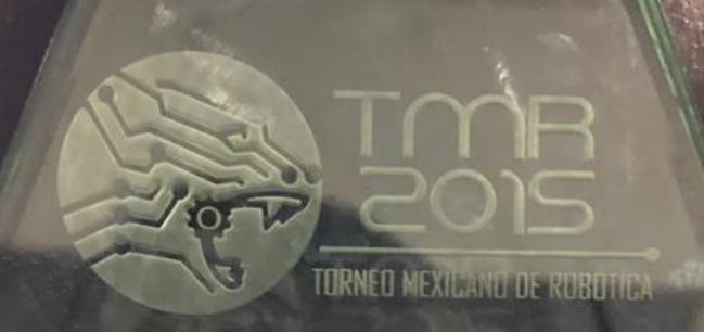
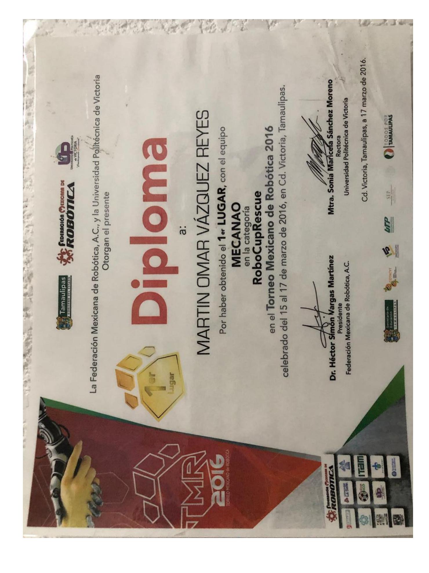
Abstract This construction work describes, installation and operating accessories of our XFinder robot, in order to participate in the TMR (regional tournament in which we are champions twice during 2015-2016 and 2nd place in 2018 you could take a look of competition results on these links http://femexrobotica.org/tmr2015/resultados.php our team name was "UTEZ UNO", https://www.femexrobotica.org/tmr2016/resultados our team name was "MECANAO", https://www.femexrobotica.org/tmr2018/ganadores/ our team name was "UTEZ-EXFINDER"). Thanks to this competition, we finally got a place Competition in the RoboCup Rescue League. Our project is a four-wheeled robotic system tele-operated suitable for indoor and outdoor used with high tensile strength, simultaneous localization and mapping (SLAM), visual detection of victims, recognition of QR codes and CO2 reading. The objective of this system is to recognize victims in any soil or land, creating a useful map for human rescue teams.
Information
Team name: XFinder team Institution: IFRobotics Team leader: Martin Omar Vazquez Reyes
INTRODUCTION
The XFinder project originally began as an "integrative task" or final course project developed by four graduate students. Months later, it seems potential on this project due to many disasters in the nearby city of Cuernavaca.
During. many national competitions, the XFinder project has taken many forms refering to the teams which they´ve worked with, ending in our current version, shown in the picture above. Our main goal is to create a robot reliable and be able to provide real-time information, during disaster when conditions threaten, human intervention exploration.
After many field tests, several broken mechanical parts and burned circuits, it is proven that this robot is ready for the toughest conditions.
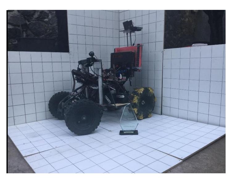
A. Improvements over previous contributions
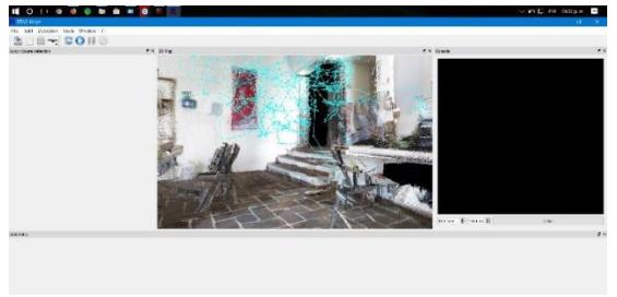
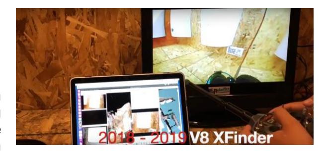
The current XFinder project has received major software upgrades than field mechanics. We are focused on the application of 3D mapping, object recognition, navigation system giving us a better location and acquisition information. We are also improving our control systems for good, clearer interaction between the operator interface and the action what robot will do.
You could see the new features in this link https://youtu.be/fxdpKCiMQUM
II. SYSTEM DESCRIPTION
A. Hardware
XFinder dimensions are 55 kg, 1 m long, 70 cm wide, 70 cm.
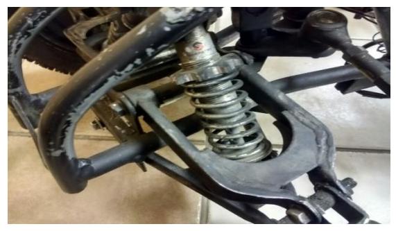
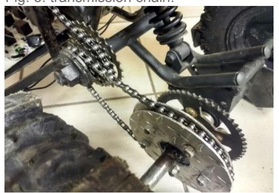
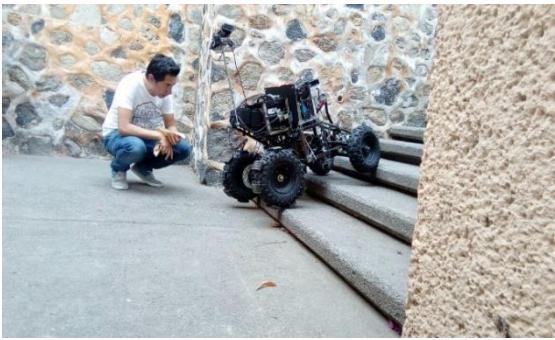
Many local competitions gave us a clear vision about implementing a system with suspension and wheels, in accordance to them we attempt to improve resistance to impact when the robot goes on uneven terrain from the ground floor or first floor whether or not there is an existence of a ramp.
B. Software
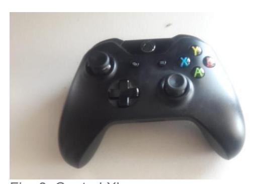
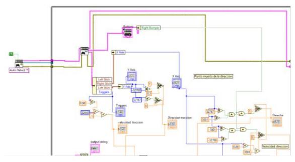
- control signals movement is performed by the Xbox One, therefore signals are sent to the costumer
C. Communication
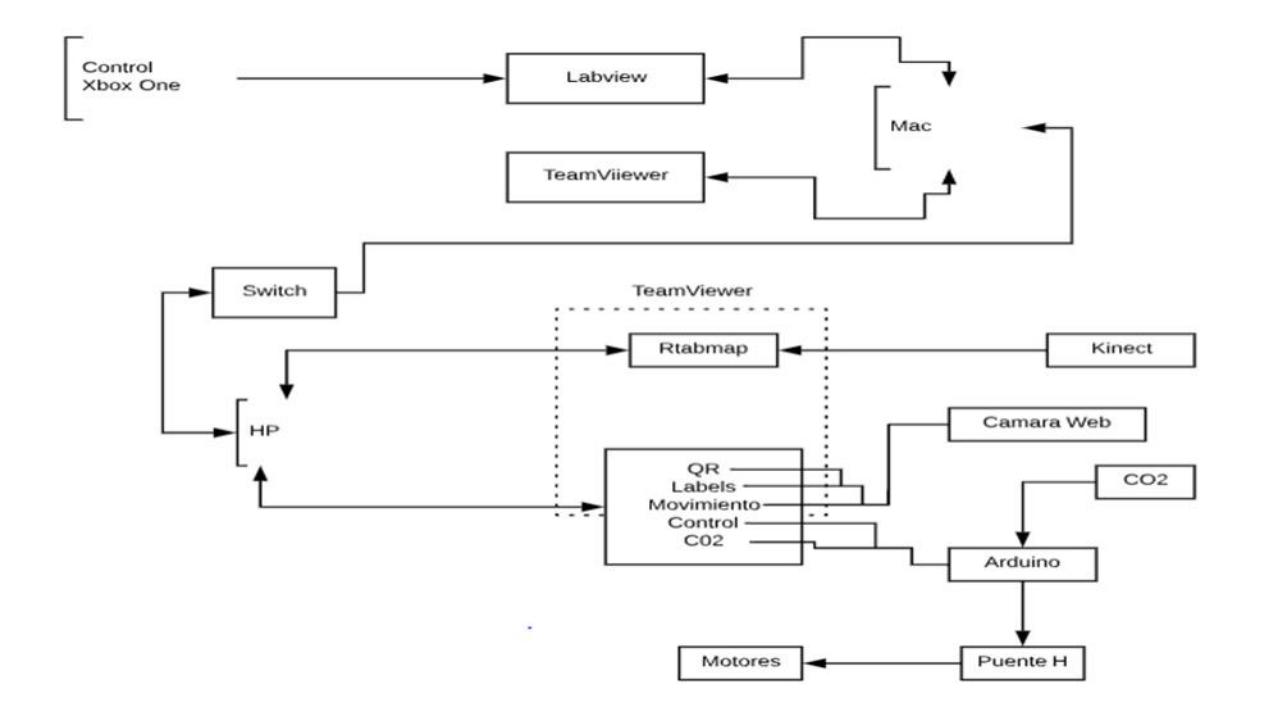
The communication is performed through the TCP / IP protocol which is responsible for connecting a server and a client that sends and receives data simultaneously in real time, said connection is made by a switch to assign the corresponding IP's (2.4 g),
D. Human-Robot Interface
1. Communication Control
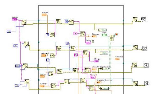
Communication TCP / IP is made by LabView. There are 2 codes depend on each other. certain code runs as a server which control signals Xbox One are acquired and according to set up parameters , numerical data will be written to send them to another code, the other computer is used as a client receiving the information command and this in turn is sent through the Arduino to control motors, However, it should be noted that the information is sent by different remote ports and to be specified in the server IP client where is going to be connected
III. REQUEST
A. Setup and breakdown
We are aware the speed of adjustment and the process of breakdown of each task is very crucial.
Our team includes XFinder robot, a laptop computer going inside the robot to send data at our station. All equipment is transported to operator station on a transport trolley.
B. Strategy Mission
In our simulations we have created two teams, one team is for the flow of vision and navigation; and the other one for 3D mapping and location. Let's deploy XFinder in the operating field and complete all possible targets in a planned routine regarding on the coordination of two teams, based on the distance and objectives of the way.
C. Experiment
Experiments have been mainly mechanical due simulation uneven terrain, debris and various types of materials like stones and sand. We expect the anatomy of XFinder in respect of all these simulations at different terrains allow us to complete the yellow or red areas of the operating field. In thesoftware area we are still linking the different programs and applications (QR mapping, object detection, motion, CO2 detection) to enrich this way, the 3D mapping and be able to send the most complete information.
D. application in the field
Places near from our work area are industrialized size, because of this, it is expected that the XFinder project could be useful in exploring these areas in case of disaster or pollution implying harm in human. Sending data in real time to a parallel rescue action team and avoid human losses
The strength of the robot is based on the movement of pulling , its size and durability to sort the obstacles, therefore, the XFinder is suitable for real-world scenarios.
Weakness: No robotic arm.
Get a robotic arm.
IV. CONCLUSION
The XFinder project was born from scrap, reuse parts, sometimes money itself, but as a team we are ready to participate and demonstrate the product of our hard work.
APPENDIX A Team and contributions
The XFinder robot has 7 members. Their names and responsibilities of each member are as follows:
Martin Omar Vazquez Reyes
- Team captain
Chavarria Santiago Luis Ashmed
- Mechanical Development
Diaz Francisco Javier Altamirano
- System control / scan
Claudio Pachecano Victor Abraham
- mechanical development
Garrido Garrido Maria de Lourdes
- Electronic design
José María García Sotelo
- Object recognition
Jonathan Cruz Nava
- Development controller
THANKS
We thank the small sponsors who have supported us to get resources and materials for the project financing, as well as our families have provide us full support in situations of adversity, lack of free time and financial support for the project and travel competences.
APPENDIX B SCHEDULES
A. Systems List
There are 3 main systems:
- Handling System in the table I
- The operator station in the table II.
- The list of hardware components on the table III.
- The list of software on the table IV.
TABLE I. Handling system
| Attribute | Value |
|---|---|
| Name | XFinder |
| Locomotion | Wheeled |
| System weight | 85 kg |
| Weight including transportation case | 90 kg |
| Transportation size | 1.0 x 0.6 x 0.66 m |
| Typical operation size | 1.0 x 0.6 x 0.78 m |
| Unpack and assembly time | 210 min |
| Startup time (off to full operation) | 5 min |
| Power consumption (idle/ typical/ max) | 60 / 560 / 1000 W |
| Battery endurance (idle/ normal/ heavy load) | 60 / 40 / 20 min |
| Maximum speed (flat/ outdoor/ rubble pile) | 0.8 / 0.6 / 0.3 m/s |
| Payload (typical, maximum) | NE |
| Arm: maximum operation height | NE |
| Arm: payload at full extend | NE |
| Support: set of bat. Chargers total weight | 2.5 kg |
| Support: set of bat. Chargers power | 1,200W (100-240V AC |
| Support: Charge time batteries (80% / 100%) | 40 min / 60 min |
| Support: Additional set of batteries weight | 3 kg |
| Any other interesting attribute | 2 electrical |
| Pistons | |
| Cost | 4000 USD |
TABLE II Operator Station
| Attribute | Value |
|---|---|
| Name | XFinder |
| station | |
| Weight system | 15 kg |
| Weight including transport size | 30 kg |
| transport size | 0.8 x 1 x 0.4 |
| m | |
| size typical operation | 0.8 x 1 x 0.4 |
| m | |
| Unpacking and assembly time | 15 minutes |
| start time (out of full operation) | 5 minutes |
| Power consumption (standby / standard / max) | NE |
| the resistance of the battery (idle load / normal / | NE |
| heavy) | |
| Any other interesting attribute | - |
| Cost | 500 USD |
TABLE III. HARDWARE COMPONENTS
| Part | Brand model | Unit price | Num. |
|---|---|---|---|
| structure of the | - | 2000 USD | one |
| robot | |||
| drive motors | - | 500 USD | two |
| drive gears | - | - | - |
| encoder unit | - | - | - |
| motor controllers | - | - | - |
| DC / DC | Regulator | - | one |
| Battery Management | Nebraska | - | - |
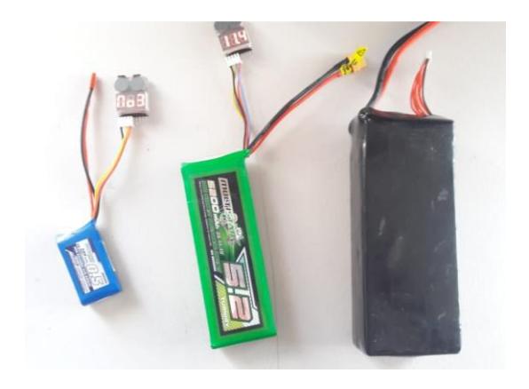
| battery | lipo, | 750 USD | 3 |
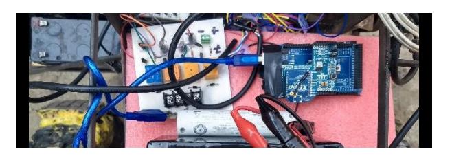
| microcontroller | Atmel | 50 USD | one |
| Computer unit | Laptops dual | - | two |
| mount | |||
| IMU | - | - | - |
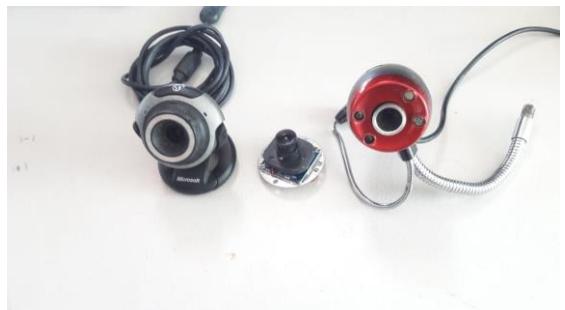
| VDO cameras | - | - | - |
| PTZ | - | - | |
| Infrared camera | - | - | |
| LFR | - | - | - |
| CO2 sensor | - | 100 USD | one |
| Battery Chargers | - | 200 USD | two |
| Robotic arm | - | - | - |
| air vehicle | - | - | - |
| Operator rugged | - | 2000 USD | one |
| laptop |
TABLE IV. SOFTWARE
| SOFTWARE | VERSION | LICENSE | USE |
|---|---|---|---|
| Start Windows | 1607 | closed | OS workstation. |
| 10. | source. | ||
| RTABMap | 0.11.14 | open | 3D mapping. |
| project. | source. | ||
| TeamViewer. | 12.0.72365. | open | Streaming |
| source. | between laptops | ||
| in the XFinder | |||
| browser. | |||
| NI LabVIEW. | 15.0. | closed | XFinder |
| source. | algorithm | ||
| browser. | |||
| OBS study. | 17.0.2. | open | Current cameras |
| source. | installed in the | ||
| XFinder. | |||
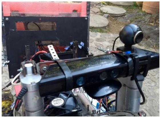
| Kinect for | 1.8.0.595 | open | required for 3D |
| Windows | source. | mapping sensor | |
| Drivers. | controllers. | ||
| Kinect for | 1.8.0.595 | open | an additional |
| Windows SDK. | source. | driver for 3D | |
| mapping sensor. | |||
| Kinect for | 1.8.0.595 | open | RGB camera |
| Windows at | source. | controller | |
| runtime. | integrated in the | ||
| sensor 3D map. |
Recognition and awards
The team has received recognition for the RoboCup Rescue achievements. This section documents the awards and achievements at the Mexican Robotics Tournament competitions.







References
- M. F. Labbe and Michaud, "Global Online detection loop close graphic based SLAM Multi-scale meets" in Proceedings IEEE International Conference / RSJ Intelligent Robotics and Systems, 2014. (From here took our main source to make our SLAM)
- J. Craig, Introduction to Mechanics and robotic control. Pearson Prentice Hall; third edition, 2005.
- M. Rashid, Power Electronics: Circuits, devices and applications. Pearson Prentice Hall; Third Edition, 2004.