RoboCup Rescue 2019 Team Description Paper iRAP SECHZIG
Amornphun Phunopas, Noppadol Pudchuen, Aran Blattler
King Mongkut's University of Technology North Bangkok
http://www.kmutnb.ac.th/en/ · https://robocup-rescue.github.io/team_description_papers/
Abstract In this paper, we would like to describe the improved construction and operation of our robot (iRAP SECHZIG), which has a long history in the first place awards of World RoboCup Rescue Robot competitions, such as iRAP PRO, iRAP JUDY, iRAP FURIOUS, iRAP JUNIOR, and iRAP ROBOT teams. Also, in the World RoboCup Rescue Robot 2018 (Montreal, Canada), we had participated in the competition again. Through the story, the robot was severely damaged by heavy workload exceeding specified limits in the final round in the World RoboCup Rescue Robot 2017. We had resolved the issues involve these issues: designing the new proper electrical driving system for heavy workload and testing competition robotic system. We came back and won first place in RoboCup Rescue 2018. In the year 2019, King Mongkut's University of Technology North Bangkok has the 60th anniversary of establishing. In the beginning, the university was founded by German Government supporting. To be honored in the special ceremony, the team is named to iRAP SECHZIG that means sixty in German. The updated information for World RoboCup Rescue Robot 2019 (Sydney, Australia), describes in this Team Description Paper. We focus on only one high mobility teleoperative robot. The teleoperative robot can move by a caterpillar module. They can identify victims very well with multi-sensors (carbon sensors, array temperature sensors, and cameras) and are able to move autonomously in the radio drop zone. The teleoperative robot has used the chain with the garden hose, which has a good material to move up the inclined surface. Additionally, the robot can create an explored map automatically and can detect the Hazmat and the QR code.
Index Terms: RoboCup Rescue, Teleoperative Robot, Autonomous Robot
I. INTRODUCTION
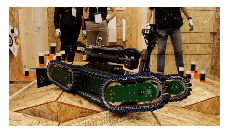
INVIGORATING ROBOT ACTIVITY PROJECT (iRAP) is the project of the team of students from King Mongkut's University of Technology North Bangkok, Thailand. This year, our robot was developed by the iRAP ROBOT team for the competition. The team members are the next generation of the legendary student teams who have gone to 1st place many times in the RoboCup Rescue Robot competition [1]. This paper introduces our approach to the rescue robot. For more than eight years, the team has designed and developed. The team has one teleoperative robot, as shown in figure 1. Our rescue robot for this competition is designed based on the proficiency of the robot on the agility test. Therefore, the robots can roam around rough terrain using the caterpillar module. Four cameras are installed on the robot to help identify the victims. Moreover, the end effector of the robotic arm is designed to install the temperature camera and CO2 sensor. In addition, the laser range finder is used to create the map for marking the victims autonomously. Our goal for this activity is to produce a practical rescue robot for reallife situations such as natural disasters like earthquakes and resulting damage like destroyed buildings. The team hopes that all we do can help people survive in a real-life disaster situation.
A. Improvements over Previous Contributions
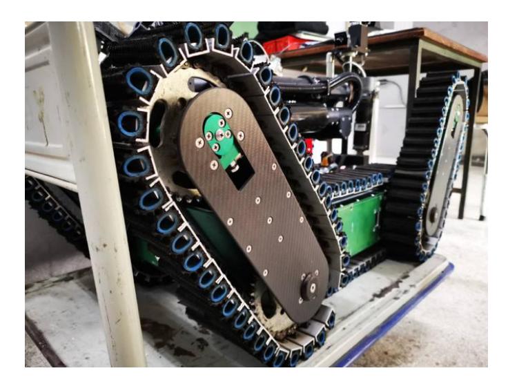
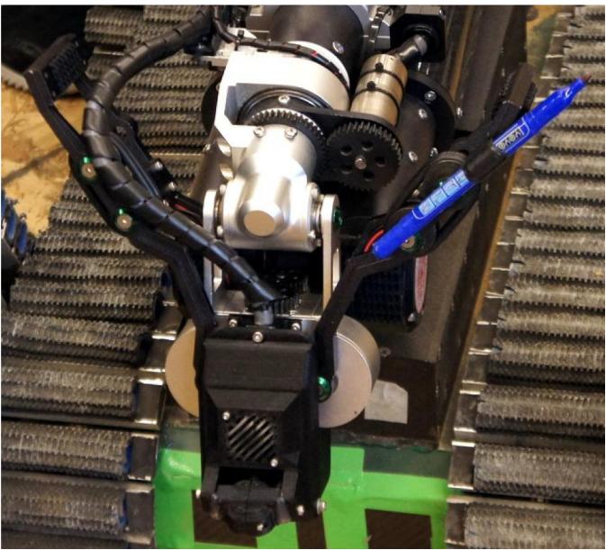
Due to the RoboCup rescue rule announced for 2019, the robots weight needs to be reduced accordingly. Our robot has a relative total weight of 77 kilograms in the 2018 competition. Through many changes in rules, the robots performance has to be upgraded by replacing new electronic components and gears. For this reason, the mechanic team has decided to modify the robots structure to support any upgrades of the robots operations. The goal is to reduce its current weight by three kilograms. We changed out some lightweight materials, such as the flipper cases material (from aluminum to carbon fiber, according to figure 2) and the nuts and bolts from stainless steel to titanium, but everything is still firm. The concept design is modular, with modules for the driving module and the robot arm. The base design has remained the same since 2013, but the robots interior continues to be developed. During the competition, our team has to maintain the robot game by game. There is a tight time limit to fix the problems that can occur at a formula one stop pit. We realize we need to design a way to remove and reinstall parts of the robot as fast as possible every year. The robot is outstanding in the best-inclass mobility category. To perform with great robot mobility in the rock and sand field is always our challenge. We keep making it better by designing the seal to prevent sand going inside the robot's body. It can damage the electronics system and cause the whole system to go down. However, the seal blocks the air ventilation and keeps the high room temperature inside the robot. The high temperature levels can cause errors resulting in the wrong operation or freezing. a severe problem occurred to our team in the final round of RoboCup 2017. The robot continued operating and got stuck; then the operator tried to move the robot out using a boost-up drive function. At that time, the power was overloaded due to the accumulated heat. The robot was fired. Since this unforgettable experience, we carefully take care of the power consumption, temperature monitoring, and cooling system. Another important module is the robot arm and the multi-functional gripper as in figure 3.
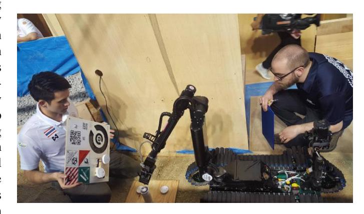
The traditional structure has been designed since 2017. We have the trustable main structure of the robot arm. We strengthen the mechanism to prevent harm to the robot arm and the gripper from the dynamic load while the robot moves as in figure 4. Moreover, it needs to upgrade to control swiftly and precisely using kinematics model. The other functions have been designed by solving problems that occurred from the last competition and improved the easiness in robot control and QR code detection. Our main focuses are exploring all areas, detecting all victims, motion detection, generating a map in 2-D and map merging. The simulated situation included many rough surfaces, hard terrains, rolling floor, stairs, and inclined floor; therefore, the rescue robot should be fast enough, lightweight and robust to circulate and explore.
II. OVERVIEW SYSTEM
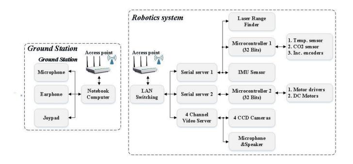
Our robots have developed in the mechanical parts, electronic circuits, and software for controlling the robot as shown in figure 5. The best mobility awards in the RoboCup Rescue competition can guarantee the capability of our robot. We have experimented the robot motion to confront the difficulties in the different terrains. Moreover, we have developed software that is parallel with the proper hardware. We try to start it up in a more advanced way. The details of our robot are as follows:
A. Hardware
The teleoperative robot weighs in at 77 kg, 1 m long, 60 cm wide, 60 cm high and can reach up to 2 m when standing up completely (or if it is in doggie style). The teleoperative robot has four flippers for balance against all kinds of obstacles. It also can flip itself back. The flippers are module design, meaning that it can still run with just one or two or three flippers or even no flipper at all. It has a 1.5 m detachable arm with 360-degree rotation and a hand that you can shake, with a servo motor to reach small spaces. It is equipped with four cameras: two at the base, one front camera, one back camera, and two on the arm that are the primary search cameras. It has three sensors: two in the front for CO2 detection, and one laser scanner in the back to map out the surrounding within a 30-meter radius. It is equipped with a flashlight for navigation, a microphone, and a speaker, allowing the rescuers to communicate with the survivors. It took us many years to develop the teleoperative robot to achieve the highest robotic mobility. There are plenty of ups and downs, but we have never given up. We had to overcome several obstacles including developing the right design, and then convince a sponsor to provide us with materials. We converted a readily available commercial converter belt to the continuous track for the robot. With this design, the robot can navigate through various terrain, including rocks, sands, debris and other surfaces. The autonomous mode robot can move and explore the map automatically. It has four cameras to detect QR code, CO2 sensor, and a thermal camera to detect the victims/C gap as in figure 6. The autonomous robot does partially succeed in the previous competition. Refer to the Tables I and the following as well as Table III in the Appendix.
Locomotion
The team is looking forward to researching the better locomotion system. The locomotion of all teleoperative robots made the conveyor belt system that the team examined from different surface characteristics of the terrain. Many parts of the robot have been improved in order to be tough, lightweight and comfortable for maintenance as much as possible. Each drive system consists of two motors: 24V, 950 rpm DC with gear-boxes for movement on the left and right. The structure of the drive system is made of aluminum. Synthetic rubber is used to make the belt. The robots have a pair of flippers that can be rotated 360 degrees.
Power (Batteries)
The robot consumes LiPO batteries because they are light and have high power to maintain the electronics, including microcontrollers and so forth. The electronics systems are low-level systems. The micro-controllers are used to interface with the motor-driven system and data acquisition.
Manipulation/ directed perception
The teleoperative robot can extend its arm from doggy style standing up to 2 meters to search for victims around the disaster area. The checkable arm consists of a temperature sensor and a CO2 sensor. The robot arm can navigate itself by knowing the end-effector position in the cartesian coordinate system.
Sensors
For victim identification, the team will analyze information from the different kinds of sensor located on the robot surveying arm. For the preliminary step, the team will check the status of the victims through the CCTV camera and measure the victims body temperature utilizing the temperature sensor. In some circumstances, this victim temperature information will be incorporated with data from the CO2 sensor and the surrounding sound, which will be received via the microphone, to analyze the situation of the victim.
B. Software
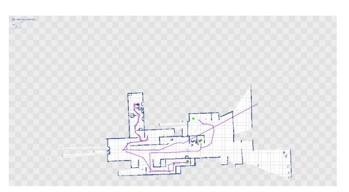
Several kinds of sensors are installed on the robot to acquire the data for processing and to create an automatic 2-D map on the operator's computer monitor. The map is generated by using the information from the distance of the robot movement from encoders, the inclination of the robot, the direction of the robot sensed by the Inertia Measurement Unit, and the distance between the robot and obstacles from the laser range finder. However, when the robot moves on different kinds of surfaces, slipping is unavoidable. This slipping is a significant problem in terms of designing and constructing the robot. Therefore, the SLAM algorithm [2], [3] is utilized to help generate the map, along with the information from the encoders, and assign positions on the X-axis, the Y-axis, and the Z-axis from the camera with the lidar scan (refer to Table IV in the Appendix). Several kinds of sensors are installed on each robot to gain crucial information about the environment around the robot. Thermal camera and CO2 detectors are mounted at the end-effector of the robot manipulator to detect the heat signature and CO2 level of the immediate environment.
The position estimation for the robot is determined by fusing pulses from encoders, the inclination from IMU, and the immediate distance from LiDAR sensors, which are then used to generate the 2-D Occupancy grid map of the environment by utilizing the SLAM library available on Robot Operating Systems. Moreover, to detect visual clues from the immediate environment such as a hazmat sign, QR code, or motion, the auto-detection algorithm of these clues was also implemented; refer to Table IV in the Appendix.
C. Communication
There are communication systems used between the operator and the robot. It uses a wire/wireless LAN based on the IEEE 802.11a standard as the main communication system. That is, it controls robots, receives video streaming from cameras on robots, and checks sensor feedback to determine the status of the robots on a computer monitor as well as for automatic map generation.
D. Human-Robot Interface
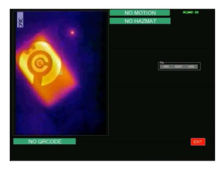
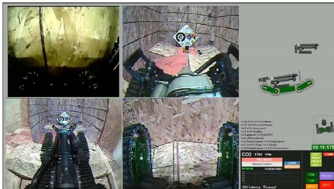
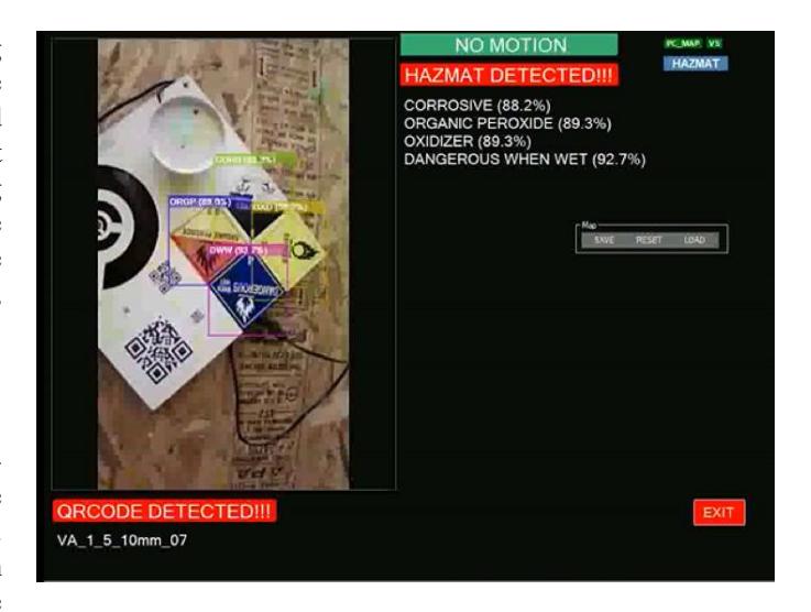
The operator can quickly get used to controlling the robot using a typical gaming joystick, two information displays, and a communication headset. The gaming joystick is used as input to control the robot and can easily be configured according to different operator preferences. The display is used to visualize the quad-channel video feed from the robot, the robot's orientation, CO2 level, thermal camera video feed, and other essential information, as shown in figure 8. Visual clue detection (motion, and hazmat and QR codes) is shown in figure 9.
The main control is based on one CPU (32-bit microcontroller). Figure 5 shows the diagram of the control system which has two main tasks as follows:
- To receive the data for identifying the status of the robots as shown in Figure 8 (Quad-video and sensors information) and create 2-D maps automatically as shown in figure 7. This information will be shown to the robot operator via a second computer monitor.
- To send the data for controlling the movement by sending the signal to the drive control for controlling the DC motor at various locations on the robots. The RS-232 communication system will be used for sending and receiving the data of the CPU. Therefore, there must be a serial server to convert the RS-232 system to the Ethernet system.
III. APPLICATION
Application and experiments.
A. Set-up and Break-Down
The speed of the set-up and break-down process of each task is very crucial. The team realizes that the faster for setup and break-down, the better time for other tasks. The team uses the aluminum case as the station. When needed, open this aluminum case and turn on the switch. The operations can be started within one minute. Inside this aluminum case, there are one monitor, a notebook, an access point, and a UPS as in figure 10. Once all the tasks are completed, the data logger and the generated map can be quickly reported. Less is more: The GUI and the status display software are being combined into one motor.
B. Experiments
We took the teleoperative robot to the test by participating in the World RoboCup Rescue Robot competition in 2018. During the competition, the objective is to find as many survivors as possible within a time limit. We were able to win those competitions due to the robot's unsurprising ability to navigate through various terrains, the camera, and the CO2 sensors' capabilities to locate and identify whether survivors are alive. Moreover, seeing the generated path on the map, the robot can automatically generate a map and mark survivors' locations, and the rescuer can compare that to the blueprint of the building. We believe this feature is one of the key differences that puts us in the best mobility category.
C. Hazmat Recognition
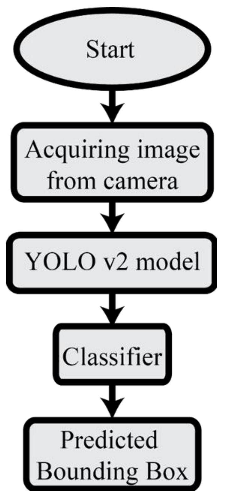
The robot has a camera on the manipulation arm to detect the hazmat tags. This year, our greatest success has been detecting the hazmat tags, using the machine learning method called YOLO[4], as shown in figure 11 (refer to Table IV in the Appendix). All 13 tags are used in the competition. Our model for recognizing the hazmat tags is shown in figure 12.
![Fig. 11. The architecture of the detection network with convolutional layers.[4]](/tdps/rescue_robot__2019__iRAP/_page_5_Figure_2.jpeg)
IV. CONCLUSION
The competition leads us to eagerly research ways to rescue humans when the world needs it. After the competition, the team knew how to make better robots. The team learned about new technologies from other countries' competitors and learned how to be a good team. The team gained many experiences. Importantly, the team knew that great competition is not practicable if we do not have good teamwork.
APPENDIX A TEAM MEMBERS AND THEIR CONTRIBUTIONS
The iRAP ROBOT has 14 members and three advisers. The names and responsibilities of each member are listed as follows:
APPENDIX A: Team Members and Contributions
| Member | Role |
|---|---|
| Mr. Thitiyos Prakaitham | Mechanical development |
| Mr. Thanut Vibutr | Mechanical development |
| Mr. Chaiyapruk Laohapanich | Mechanical design and Driver |
| Mr. Chinnawut Ngiamngamsri | Mechanical development |
| Mr. Thammarit Sivalai | Mechanical development |
| Mr. Jirakran Sukcharoen | Mechanical development |
| Mr. Peeyaphoom Thanawutthianan | Mechanical development |
| Mr. Natinan Kuttanan | Electronic and Electrical design |
| Mr. Pubadee Bunjing | Electronic and Electrical design |
| Mr. Poonkit Sritrakanpathom | Electronic and Electrical design |
| Mr. Tanawit Sinsukudomchai | System interface |
| Mr. Artit Narasetthakul | Embedded system |
| Mr. Theerawath Phetpoon | Map systems |
| Mr. Aran Blattler | Team manager (Team Leader) |
| Mr. Noppadol Pudchuen | Adviser |
| Asst.Prof. Chatchai Sermpongpan | Adviser |
| Dr. Amornphun Phunopas | Adviser |
APPENDIX B LISTS
There are four main systems:
- The Hardware System in the Tables I
- The Operator Station in the Tables II
- The Hardware Components List in the Tables III
- The Software List in the Tables IV
A. Systems List
The main systems and their specifications are listed in the following tables.
TABLE I HARDWARE SYSTEM
| Attribute | Value |
|---|---|
| Name | iRAP SECHZIG |
| Locomotion | tracked |
| System Weight | 77kg |
| Weight including transportation case | 100kg |
| Transportation size | 0.8 x 1.35 x 0.8 m |
| Typical operation size | 0.6 x 1.2 x 0.6 m |
| Unpack and assembly time | 180 min |
| Startup time (off to full operation) | 15 min |
| Power consumption (idle/ typical/ max) | ND |
| Battery endurance (idle/ normal/ heavy load) | ND |
| Maximum speed (flat/ outdoor/ rubble pile) | ND |
| Payload (typical, maximum) | 5 kg |
| Arm: maximum operation height | 2 m |
| Arm: payload at full extend | 15kg |
| Support: set of bat. chargers total weight | ND |
| Support: set of bat. chargers power | ND |
| Support: Charge time batteries (80%/ 100%) | ND |
| Support: Additional set of batteries weight | 1.3kg |
| Any other interesting attribute | - |
| Cost | 23000 USD |
TABLE II OPERATOR STATION
| Attribute | Value |
|---|---|
| Name | iRAP STATION |
| System Weight | 15kg |
| Weight including transportation case | 30kg |
| Transportation size | 0.8 x 1 x 0.4 m |
| Typical operation size | 0.8 x 1 x 0.4 m |
| Unpack and assembly time | 30 min |
| Startup time (off to full operation) | 20 min |
| Power consumption (idle/ typical/ max) | ND |
| Battery endurance (idle/ normal/ heavy load) | ND |
| Any other interesting attribute | - |
| Cost | 2000 USD |
TABLE III HARDWARE COMPONENTS LIST
| Part | Brand & Model | Unit Price | Num. |
|---|---|---|---|
| Robot structure | - | 2500 USD | 2 |
| Drive motors | Maxon | 1200 USD | 2 |
| Drive gears | Planetary Gearhead GP 62 | 2 | |
| Drive encoder | Omron rotary encoder | 120 USD | 2 |
| Motor drivers | ND | - | 2 |
| DC/DC | Regulator | - | 1 |
| Battery Management | ND | - | 1 |
| Batteries | LiPO | - | 1 |
| Micro controller | Arduino, Pic | - | 1 |
| Computing Unit | Mini PC, Embedded | - | 1 |
| WiFi Adapter | Access point IEEE 802.11a | 190 USD | 1 |
| IMU | xsens | 4 | |
| VDO Cameras | Microsoft | 320 USD | 4 |
| PTZ Camera | ND | - | 1 |
| Infrared Camera | ND | - | 1 |
| LRF | ND | - | 2 |
| CO2 Sensor | ND | 125 USD | 1 |
| Temperature Sensor | Lepton | 2400 USD | 1 |
| Battery Chargers | ND | 100 USD | 10 |
| 6-axis Robot Arm | ND | 23000 USD | 1 |
| Aerial Vehicle | ND | 2000USD | 1 |
| Rugged Operator Laptop | ND | 2000USD | 1 |
TABLE IV SOFTWARE LIST
| Name | Version | License | Usage |
|---|---|---|---|
| Ubuntu | 16.04.3 | open | Utility |
| ROS | Kinetic | BSD | Utility |
| YOLO | 2.0 | BSD | Hazmat sign Detection |
| OpenCV [5], [6] | 2.4.8 | BSD | Haar: Victim detection, Motion Detection, QR Code detection |
| EMGU [7] | 2.4.8 | BSD | LBP: Hazmat detection |
| Hector SLAM [8] | 0.3.4 | BSD | 2D SLAM |
| iRap 3D SLAM | - | closed source | 3D SLAM |
| GUI Propreietary | 1.0.2 | KMUTNB | Operator Station, Hazmat sign Detection |
ACKNOWLEDGMENT
The authors would like to thank the King Mongkut's University of Technology North Bangkok for regularly supporting the iRAP Robot in participating the World Robocup Rescue Robot Competition.
References
[1] A. Phunopas, A. Blattler, and N. Pudchuen, "irap robot: World robocup rescue championship 2016 and best in class mobility award," Robot World Cup. Springer, Cham, 2016. [2] R. Siegwart, I. R. Nourbakhsh, and D. Scaramuzza, Introduction to Autonomous Mobile Robots. The MIT Press; second edition edition, 2011. [3] S. Thrun, W. Burgard, and D. Fox, Probabilistic Robotics. The MIT Press, 2005. [4] J. Redmon and A. Farhadi, "Yolo9000: Better, faster, stronger," 2017 IEEE Conference on Computer Vision and Pattern Recognition (CVPR), pp. 6517–6525, 2017. [5] P. Viola and M. Jones, "Rapid object detection using a boosted cascade of simple features," in Computer Vision and Pattern Recognition, 2001. CVPR 2001. Proceedings of the 2001 IEEE Computer Society Conference on, vol. 1, 2001, pp. I–511–I–518 vol.1. [6] R. Lienhart and J. Maydt, "An extended set of haar-like features for rapid object detection," in Image Processing. 2002. Proceedings. 2002 International Conference on, vol. 1, 2002, pp. I–900–I–903 vol.1. [7] S. Liao, X. Zhu, Z. Lei, L. Zhang, and S. Li, "Learning multi-scale block local binary patterns for face recognition," in Advances in Biometrics, ser. Lecture Notes in Computer Science, S.-W. Lee and S. Li, Eds. Springer Berlin Heidelberg, 2007, vol. 4642, pp. 828–837. [Online]. Available: http://dx.doi.org/10.1007/978-3-540-74549-5_87 [8] S. Kohlbrecher, J. Meyer, O. von Stryk, and U. Klingauf, "A flexible and scalable slam system with full 3d motion estimation," in Proc. IEEE International Symposium on Safety, Security and Rescue Robotics (SSRR). IEEE, November 2011.