RRL2022 BART LAB Rescue Robotics Team Thailand
Jackrit Suthakorn, Songpol Ongwattanakul, Nantida Nillahoot, Pittawat Thiuthipsakul, Branesh Madhavan Pillai, Mayur Kishore, Panuwat Oiamwong, Tanadul Somboonwong, Daral Maesincee, Thitamorn Panyawongngam
BART LAB, Mahidol University
https://bartlabmu.org · https://drive.google.com/drive/folders/1md-u0ot_FWpHS_awDCmPPzLjXm2Z0wCQ
Abstract This paper addresses BART LAB team for participation in the 2022 RoboCup Rescue Robot competition. Contributing in regional and world events since 2006. All members' concentration has been on a reliable lightweight semiautonomous rough-terrain robot. We provide an overview of the system as manufactured parts, CAD files, prospective programs and implemented control system, for example, locomotion system, communication hardware, manipulator pose estimation software (MPE) and user interface (UI). As a contribution to the RoboCup Rescue community, BART LAB team is developing a reliable rescue robot to employ in a real disaster situation around the world.
I. INTRODUCTION
B ART LAB Rescue Robotics Team is a one of rescue robotics team from Thailand and presently consists of fifteen members and two robots. The first is a rough terrain robot calls as TeleOp VII, which composed of two functions (Tele-Operative and Autonomous function) and an aerial robot calls as AerialBot I is introduced with a light-weight mapping and a vital sensing system in this year. We constantly researching and developing robots and has participated in regional robot competitions since 2006.
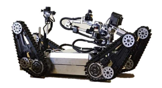
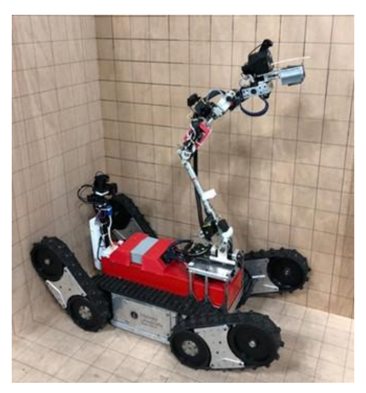
In 2008, Thailand Rescue Robot Championship (TRR 2008), we were one of the 8-finalist teams from 80 plus participating teams and received the Best-In-Class award for its autonomous robot. In early 2009, we attended the RoboCup Japan Open 2009 in the Rescue League with ten Japanese teams, where the team received second place. Additionally, we were awarded the 'SICE Award" for data collection and management of the au-tonomous robot. TeleOp VII and TeleOp VI were shown in Fig.1 and Fig. 2 respectively
At the 2009 Thailand Rescue Robot Championship (TRR 2009), we were the Winner and awarded Best Autonomy for its autonomous robot. TRR 2009 was one of the most competitive Rescue Robot League in the work with more than 100 exceptional teams, consisting of six international teams from four countries (Australia, NuTech-R: Japan, NIIT-Blue: Japan, Jacobs University: Germany, Pasargard: Iran, and Resquake: Iran). In early 2010, the team attended RoboCup Japan Open 2010 was awarded 1st Place Rescue Robot Award. After commendable performance at these two competitions, we participated at World RoboCup Rescue 2010, Singapore as the official representative team. Finally, BART LAB Rescue Robotics team was awarded the 1st runner-up for its Rescue Robot.
In 2011 to 2015, our team continued to receive awards, 1st Place Rescue Robot Award and 1st Runner-up Rescue Robot Award at RoboCup Japan Open 2011 and 2012, respectively. Furthermore, the team was awarded the Best Autonomy Award at Thailand Robot Championship 2012 in the Rescue Robot League, 3rd Place Res-cue Robot Award at World RoboCup Rescue 2014, Brazil. In early 2015, the team attended RoboCup Iran Open 2015 was awarded 3rd Place Rescue Robot Award.
Tele-operative robots are similar in their design yet have different performance, since TeleOp VII has better driving components. Tele-operative robots are highly mobile robots with tracking locomotion systems, making the robots more mobile in testing arenas. The robots consist of four flippers, which are controlled independently to improve their mobility in various terrains (two flippers at the front end and two more at the rear end). The robots also employ manipulators which are controlled using inverse-kinematics. The victim-sensing unit is attached to the end-effector of this manipulator, to improve the victims sensing ability and retrieving information. The sensing unit contains various life signal detecting sensors, for example, thermal camera, real-time motion image detector, carbon dioxide sensor, and two-way voice communication system. The manipulator has multiple degrees of freedom with both rotational and prismatic joints, giving the robot a compact folding-size with a highly efficient workspace. The manipulator is controlled by a special device (Phantom Omni haptic device) for fine movement of the end-effector. The autonomous robot of the team is designed for victim identification using image processing and heat imaging technology. On the other hand, the autonomous function, navigates the TeleOp VII by employing a laser-scanner system and an efficient algorithm which allows the robot to autonomously navigate in testing arenas without hitting walls. Figure 2 shows the previous version of the autonomous robot which is used as a base for a developed autonomous algorithm in the TeleOp VII.
The last one, the AerialBot I introduced this year. The robot bases on the commercial robot with the novel lightweight structure with a laser range finder and IMU for 3D maps with 3D map visibility Graph Technique. However, the teleoperative and autonomous robots are equipped with SLAM system to generate 2-D maps to guide the responders after the rescue robots raid the disaster area.
RoboCup Rescue is an opportunity towards a remarkably efficient robot exercise in response to a disaster. To handle such situation regardless of being actual or exercise, robot and the team behind it would get through high amount of data, decisions, control parameters, time shortage and stress. Reliable rescue robotics in terms of structure robustness and control would consider as the critical factors for a robot. For that reasons our team is mainly focusing on these aspects for a rough terrain robot. To obtain so, our introduced robots have had four independently controlled flippers, particular platform and control system. These require some principle as: components compactness to save space, the ability to withstand high impact or unforeseen situations and harmonic design to combine subcomponent together for having expected functionality and well interactive parts to connect hardware and software together well.
In conclusion, we comprise of highly mobile rescue robots in relation to those built by Thai teams for previous World RoboCup Rescue Leagues. Over the years, we have improved its autonomous robot and the quality of real-time map generation. The ultimate aim of our research and development team is to produce reliable rescue robots to be employed in real disaster situations around the world and to be improved a possibility of victims searching for a rescue team.
A. Improvements over Previous Contributions
In the last robot, all parts depend on each other in terms of adjustment and installation. This means any misalignment in one part bring about incorrect position in other parts. For example, platform as a chassis meant to be robust; however, any deflection in this, leads to propulsion drive malfunction! In latest BART LAB robot, all the parts are design and engaged independently as modules. Variety of particular connector are used to connect modules together. The overall improvements are itemized as follows:
- Improved platform design based on the previous models' data.
- Weight reduction by composites like carbon fiber and reinforced engineering plastics.
- New flippers' design form rectangular shape to triangular one
- Light Weight carbon fiber reinforced manipulator.
- Secondary communication plan in radio frequency (FR) band.
B. Scientific Publications
The rescue robot team at the Center for Biomedical and Robotics Technology LAB (BART LAB) presently have been built a rescue robot for the past 15 years and have successfully deployed robot in diverse conditions, either to test the robot capability in robot competition or help rescue team in real situation [1], [2]. Observer-Based Controller (OBC) is used to calculate the varying acceleration and the contact point when the BART LAB rescue robot is maneuvering on the unknown pathway [3]. OBC evaluates and compensates both the varying acceleration and robots position using torque observer and the predictable torque based on sensorless control method [4]. Recent studies have revealed that equipping robots with sensors makes them more effective in search and rescue missions [5][6].
II. SYSTEM DESCRIPTION
TeleOp VII is a new tele-operative robot after TeleOp VI, designed and manufactured by BART LAB team. This is a medium size Train Rescue Robot (TRR), as the next generation solution for disaster intervention in rough terrains. AIRobot is equipped with variety of actuators and hardware packages like manipulator arm, four changeable independent flippers, replaceable end-effectors, thermal camera, digital cameras and laser pointer. This robot is design to fulfill capacity of a rough terrain robot in terms of strength, search and manipulation as majority of requirements for Disaster Response Force (DRF) and Military Forces (MF) in field of TRR.
AIRobot is designed to be light weight around 60 Kg (10 Kg lighter than TeleOp VI), efficient in terms of actuation energy consumption, mechanism simplicity, selectable camera to reduce processing and consequently saving energy. It is a modular robot regarding component installations and maintenance simplicity; moreover, it has configurable controlling system for flipper angulation. For instance, the flipper part is designed to be altered with another with a fast connector mechanism. It is also possible to alter right side flipper with left side one to make a new configuration for the situations that robot needs longer flippers.
To save weight, majority of robot subcomponents are made of engineering plastics (EPs) and minority of those are reinforced carbon fiber, reinforced aluminum- carbon fiber and steel. The non-metal materials have the advantages like: strength, rust resistance and low density; however, using them needs much of attention and analysis in terms of fatigue and nonlinear displacement [7]. EPs intrinsically are not only be able to damp the vibration and impacts, but also, they are inexpensive material with high performance and high machinability which nominate them as the low-cost resources comparing to light metals like aluminum. In TeleOp VII, designed components have as both structural role and suspension role; however, to predict the behavior of this combined characteristics, all critical parts were analyzed by finite element method FEM software.
TeleOp VII is passing task-based plan which means Based on the anticipated tasks robot is designed and our steps can be listed as: first, its conceptual design introduced then overall CAD model and consequently weight evaluated. By having these, power of propulsion and flipper drives have been calculated and verified by power method to check if the maximum mechanical powers meet those of electrical. These loops have been checked through each mobility and maneuvering tests to see if the robot can accomplish them or not (See Fig. 15).
A. Hardware
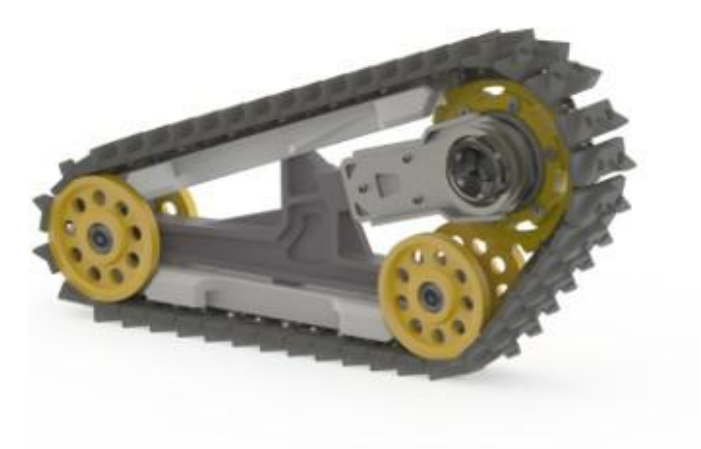
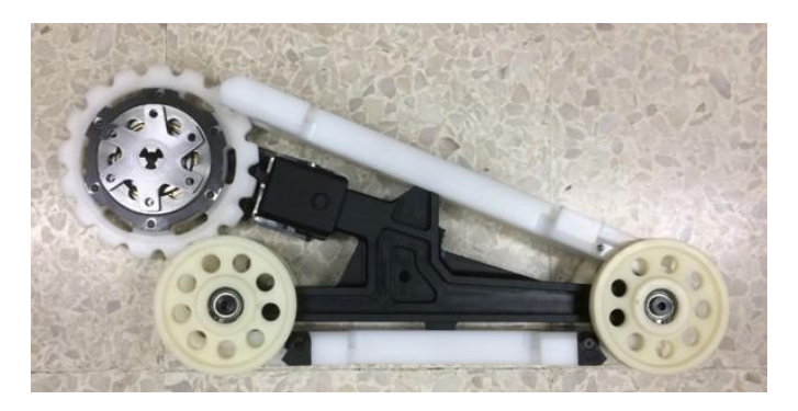
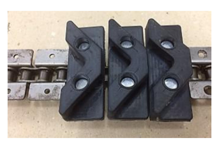
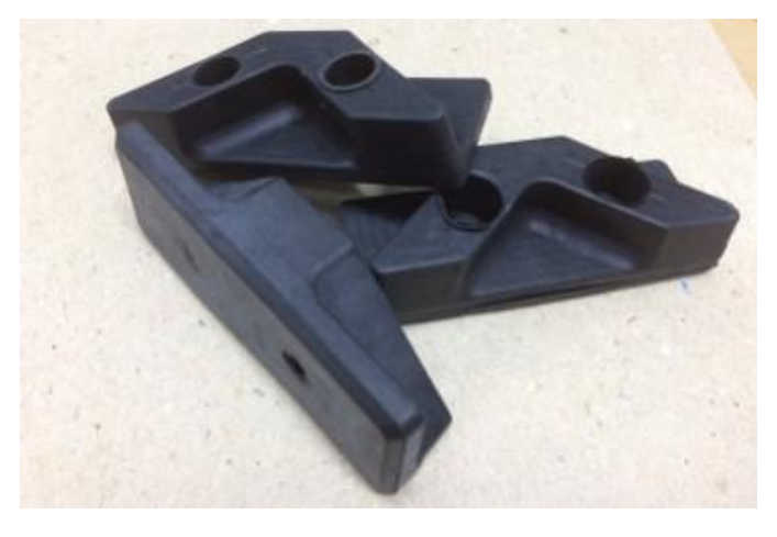
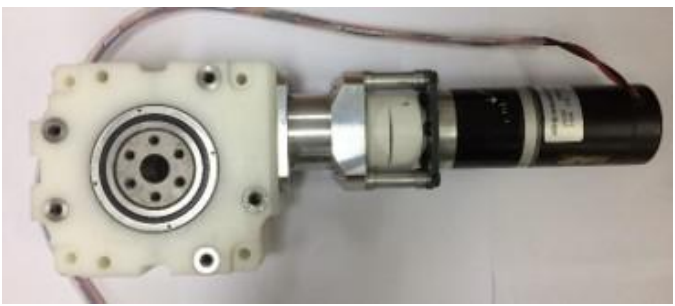
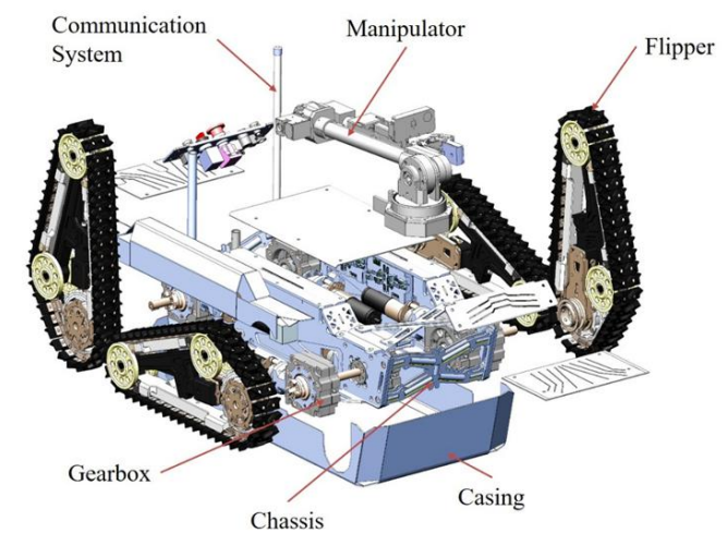
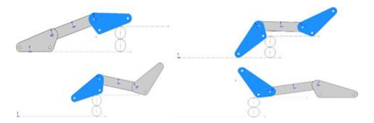
1) Locomotion: TeleOp VII has high mobility and flexibility thanks to four independent chain-rubber-equipped flippers (FICF) and light weight (see Fig. 3). Each flipper can be installed by a mechanical fast connector. One Flipper plays two roles as: propulsion and angulation. On the other hand, flipper run the robot forward/backward and at the same time its angle is adjustable. A hypoid gearbox and a Maxon motor (24V, 170W) connected to the flipper's sprocket for propulsion drive. At the same time, telescopically another geared motor with different gear ratio connected to the body of the flipper to provide angulation movement (see Fig. 6). Apart from bearings and their housings all parts are plastic (Fig. 4). BARTLAB has had a great experience of using track belt, chain-rubber and timing belt; however, we found combination of chain and rubber very simple, light and reliable. The disadvantages of using chain are being heavy and noisy, but using plastic sprocket, plastic guide rail, non- metal components and particular type of rubber reduced those unwanted effects significantly (see Fig. 4 and Fig. 5).
Rubber teeth on the flippers are intended to cope with variety of surfaces and reduces the noise taking place during robot turning (Fig. 7). To increase power transmission efficiency from motor to sprocket, a gearbox is manufactured to transmit the power (see Fig. 7). This unit can independently assemble or dismantle for maintenance. Displacement and deflection the chassis would not affect the gears contact area so that having a rigid-stiff structure would not be necessary. The gearbox itself is plastic and reinforce by carbon steel.
2) Manipulation: Manipulation is performed with an aid of a six degrees of freedom arm consisting of a gripper as the end-effector. The first three joints of the manipulator are actuated by Dynamixel XM540-W270-R actuators interfaced with planetary gears for essential reduction and the self-locking ability. Rest of the joints are directly driven by the same actuator model. The joints are connected with each other using aluminum tube and most of the linkages are constructed using acetal for significant strength to weight ratio. The overall manipulation span is about one meter while it can support a maximum payload of 1500 grams in an extensively flexed position. The manipulator comprises of a depth camera to aid in manipulation and navigation.
3) Power (Batteries): Majority of time TeleOp VII is going to use 4 of 24V Li-Po batteries, with 6000 mAh, as a main power source for both platform and manipulator. For some experiments a new generation battery as OXIS will probably test.
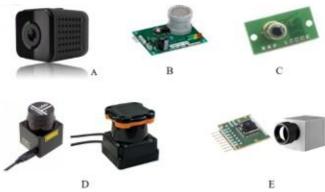
4) Sensors and cameras: There are two DC brushless motors for each corner of robot, each has one Hall Effect sensor as an encoder. In addition, each flipper has its own Hall Effect sensor to find the home position physically. On the platform, there are four cameras, MCM-4350FISH for front and back. For inertial and platform angle measurements, MPU-6000 6 axis IMU has been used. The robots are equipped with a victim sensing unit including Carbon dioxide sensor (C) Heat sensor (D) Sensor Range Finder (E) Thermal sensor to search for the vital signs. The sensors utilized in our system are listed as shown in Fig. 8.
A detecting system for the autonomous function is divided into 2 types: 1- image detection from camera is used to monitor and analyze the data from victim such as motion detection, QR code detection, and reading the text in an image and 2- Thermal sensor to detect heat of a victim inside any area. Thermal sensors are mounted on the manipulator to be able to search and swing for any heat source as the victim. QR code detection is a task, which is achieving through image processing. It can be done by taking a video or photo. The QR code detection flow chart is shown below (Fig. 9).
The hazmat detection is implemented based on SIFT and Surf to detect key point on a photo. The template of hazmat has a detection database. In real-time searching the extracted key points are continuously comparing with the database.

B. Communication
BART LAB Rescue Robotics team employs an access points connected via Wireless LAN 802.11AC 5 GHz to communicate through the robot and station with bridging technique. The default setting is Channel 36 which is a modifiable to any other requested available channel.
C. Software and Human-Robot Interface
Refer to Table IV in the Appendix. Our control method and human-robot interface can be separated into two groups: 1- Control and interface on tele-operative function. 2- Control and interface on autonomous function. These two groups are discussed in further detail below.
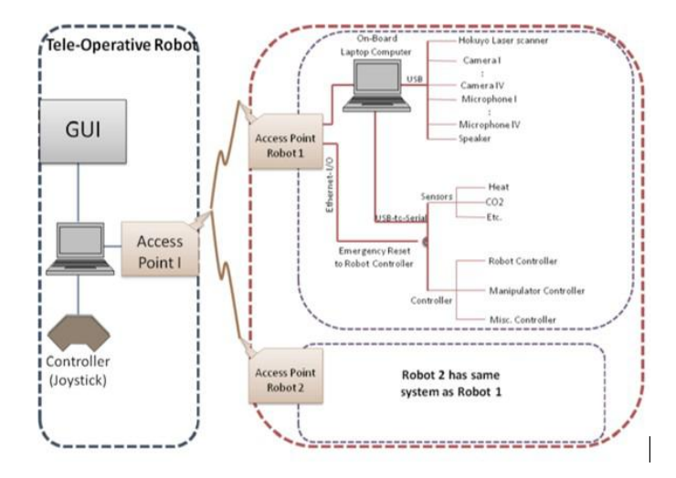
1) Control Method and Human-Robot Interface of Tele-Operative Function: The control system for the tele-operative robots is illustrated in the Fig. 10. The onboard controlling system communicates with the operator station via Wireless LAN 802.11AC access points. Another onboard access point on the robot with a fanless onboard computer would receive the commands and send the processed data to the station. This data is come from USB devices and sensors (e.g. cameras, microphones, speakers and Hokuyo laser range finder or Hokuyo scanning range finder). The computer communicates with the robot via USB ports and serial ports. The on-the-robot computer controls the propulsion, manipulator, other actuators and hardware by PID control system. The robot also has an emergency button system which stops or recovers the robot control system.
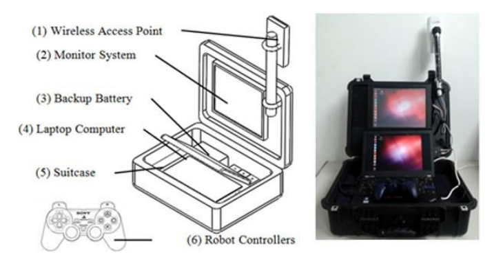
Operator station, similar to previous model, is a suitcasesized mobile unit. Moreover, there are laptop, robot controllers, backup power, power-connection, wireless access point and a monitor. The Rescue operator station is shown in Fig. 11. Each subunits of the operator station is discussed in detail below:
- Wireless Access Point: The Wireless Access Point is connected to the on board laptop.
- Monitor System: We modified lid of suitcase to attach the touch screen monitor (300 250 50mm or 12inch). Monitor will display the real time cameras output on the robot and also GUI, sensor data display (e.g. heat, CO2, etc.) robot heading, communication controller, configuration display of robot platform, pre-set robot configuration controller, and a controller for inverse- kinematic manipulator.
- Backup Power: We used UPS for backup and to protect the operator station. We need to use electricity just a few minutes to setup the operator station system before competition. The UPS has a capacity of 1000VA/550 watts and it can backup power for about 20-30 minutes.
- Laptop: Laptop is the main processor in the operator station as a server. It should have at least 1 LAN channel, 1 USB channel, 1 speaker channel and 1 VGA port.
- Suitcase: We used Pelican 1520. It is watertight, crushproof and dust proof and very strong. The Pelican 1520 offers an interior storage area of 18.0612.896.72 inch.
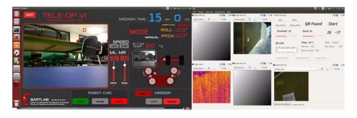
- Robot Controllers: We used gamepad type controllers. It is a type of controller held in two hands, where the fingers, especially the thumbs are used to provide input signal. It is used to control the robot flipper and robot manipulator. Fig. 12 displays information on the GUI. (A) Showing 4 view from 4 onboard cameras, sensor data (e.g. Heat, CO2), robot posture, communication controller, pre-set controller configuration, and the manipulator inverse-kinematic controller.
2) Control Method and Human-Robot-Interface of the Autonomous Function: The control scheme utilized for the autonomous function is similar to that of the tele-operative function. The difference of this control system is that the robot navigates itself autonomously and can also detect a victim automatically. More aspects of the autonomous navigation, like: map generation, navigation and localization, are discussed later. At the starting point, the autonomous robot has to be launched manually, after that it would travel autonomously.
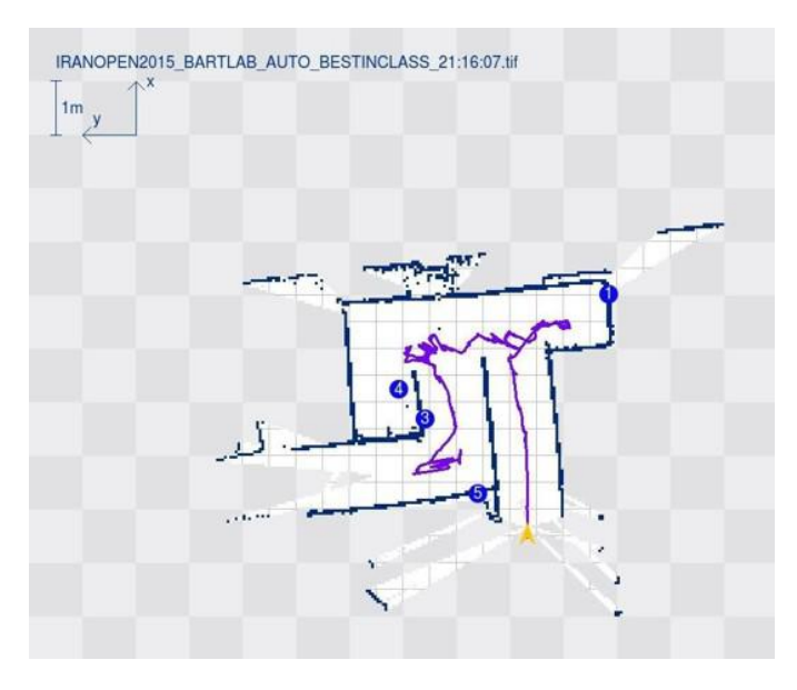
3) Map generation/ printing: Our robot is mainly governed by ROS operation. G-Mapping package from the open SLAM is used to generate a map. First, the map is defined by an occupancy grid, which has a high resolution, of about 0.05 meter per pixel. There are two inputs that create the map which are: 1-the laser range finder which is used to measure the distance of objects or structures around the robot at 180 degrees and 2) the odometry of the robot which is used by the wheel encoder to calculate the distance the robot has traveled in the axial direction. At the same time inertia measurement unit (IMU) measures the robot orientation. Fig. 13 shows generated map in RoboCup Iran Open 2015 competition.
4) Fuzzy Logic Algorithm for Autonomous Running with Obstacle Avoidance: Our autonomous robot uses the fuzzy logic algorithm to run and avoid obstacles. The fuzzy logic algorithm uses distance information collected by the laser range finder. This device provides data from ten directions following the pan scan direction. These directions are chosen to reduce the amount of data and computation time within the algorithm. A filter is applied to reduce the error before the data is turned into the membership function for Fuzzy sets. The membership function has a range from zero to one as algorithm input. For the fuzzy rule design, obstacle avoidance and distance decrease as the robot moves around the area, therefore the robot reduces its speed at each side of the driving system. The fuzzy set is divided into three categories: low, medium and far. These fuzzy categories correspond to obstacles and choose the minimum distance for obstacle avoidance. The fuzzy outputs using the If-Then Rule based on the orientation of the robot and the velocity of each driving motor. The output is computed in real-time based on the environment and sent to the propulsion unit to respond to the environment immediately.
III. APPLICATION
A. Set-up and Break-Down
The operator station like the previous one is an easy-to-use suitcase-sized unit. This system is employed to control and communicate the AIRobot. Start a task is as easy as switching the laptop and robot on, and the operator can access to the robots via Wi-Fi.
B. Mission Strategy
Strategically, the robot has a configuration mode to specify the task. On the other hand, for each task robot will configure its mechanical, sensory and control part to reduce driver's considerations. Since the robot has lower weight and high strength, so it has relatively lower inertia which would increase the mobility and maneuverability. With the same approach, it is expected the new carbon fiber manipulator also be more agile and accurate.
C. Experiments
Experiments can be categorized as components experiments and Robot experiment. Since the flipper has a critical role, its model has been analyzed with FEM and subjected to the different forces and bending moments. The flipper parts has been tested under specific weigh (830N, flexural test) to make sure that it confirm FEM data. BART LAB at Mahidol University, Salaya campus, Thailand has a construction for practicing and training. In the arena, majority of rescue robot tests including the maneuvering, mobility and dexterity are available.
D. Application in the Field
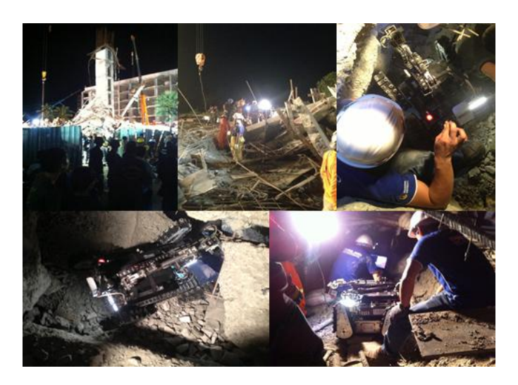
On August 11, 2014, U-place condo tale, the six-floors building under construction, collapsed in Pathumthani, THAI-LAND. There were a number of injured people trapped in the collapsed building. BART LAB Rescue Robotics team was called by the rescue team to join the survey and rescue mission on site. At 01.00 am on August 12, BART LAB Rescue Robotics team arrived and col-laborated with Director-General of Department of Disas-ter Prevention and Mitigation who was in charge of the rescue operation. The top floor of the building was under construction and collapsed into the sandwich structure. Some of the injured were trapped at different depths that were difficult to access from the outside. BART LAB Rescue Robot is designed to operate in rough and com-plex terrain. However, the height of the robot is 60 cm, which limits the regions the robot is able to gain access to. During the operation the rescue team made the hole to access 3 to 4 floors to locate survivors. The pre-observation was possible to indicate a survivor. BART LAB Rescue Robot was assigned to survey the scene and provide more information on the location of survivors and the structure of the collapse.
The robot was remotely operated from the outside station and passed through the 6th floor to the 4th floor. The hole became narrower and lower, additional obstacles included the steel rods that reinforce the concrete structure. Due to these major ob-stacles, the movement of robot was limited. However, this is the first mission that BART LAB Rescue Robotics team experienced as part of an on-site operation (Fig. 14). The collaboration with the rescue team provided the team with valuable feedback for future improvement and development.
Our ultimate goal is to produce a reliable rescue robot, through research and development, for application in a real disaster site around the world. We strongly believe that our team robots are prepared to perform a rescue task in the real world. BARTLAB has developed several rescue robots since 2006 and one of them have been used in a real disaster as a collapsed building in August 11, 2014 [7]. Since then, this on-site experience has motivated team to work on improving and optimizing of both mechanical and communication system. It is expected, TeleOp VII shows better performance in both mobility, dexterity and communicating comparing to the last Tele-operative version. Overall this robot is another step toward real disaster response. The installed manipulator would not be able to manipulate with a force higher than 1Kg. This team is planning to enhance capability of this part in next version. Reducing robot weight, size and cost.
IV. CONCLUSION
In conclusion, over these years we have improved and now our motives, experience and knowledge make the way clearer. Since the finished robot has yet to come, we cannot experimentally show how much better we become comparing to the previous robot, but improvement and learning will be inevitable on this way.
APPENDIX A TEAM MEMBERS AND THEIR CONTRIBUTIONS
• Jackrit Suthakorn Executive Advisor • Songpol Ongwattanakul Co-Advisor • Thitamorn Panyawongngam Mechanical Designer • Nantida Nillahoot Senior Member and HRI • Pittawat Thiuthipsakul Team Leader • Branesh Madhavan Pillai Control Supervisor • Mayur Kishore Mechanical Designer • Panuwat Oiamwong Mechanical Designer • Tanadul Somboonwong Programmer • Daral Maesincee System Integrator
APPENDIX B CAD DRAWINGS
(CAD drawings reference provided in appendix)
APPENDIX C LISTS
TABLE I MANIPULATION SYSTEM
| Attribute | Value |
|---|---|
| Name | AIRobot |
| Locomotion | Chain-rubber tracked |
| System Weight | 55kg |
| Weight including transportation case | 75kg |
| Transportation size | 0.6 x 0.6 x 0.5 m |
| Typical operation size | 803 x 532 x 587 mm |
| Unpack and assembly time | 120 min |
| Startup time (off to full operation) | 15 min |
| Power consumption (idle/ typical/ max) | 60 / 200 / 800 W |
| Battery endurance (idle/ normal/ heavy load) | 2240 / 120 / 60 min |
| Maximum speed (flat/ outdoor/ rubble pile) | 4 / 1 / - m/s |
| Payload (typical, maximum) | 1/ 2 kg |
| Arm: maximum operation height | 100 cm |
| Arm: payload at full extend | 1kg |
| Support: set of bat. chargers total weight | 4kg |
| Support: Charge time batteries (80%/ 100%) | 90 / 120 min |
| Support: Additional set of batteries weight | 2kg |
| Cost | 25000 USD |
TABLE II OPERATOR STATION
| Attribute | Value |
|---|---|
| Name | AIRobot-OP |
| System Weight | 6kg |
| Weight including transportation case | 12kg |
| Transportation size | 45.5 x 32.7 x 17 cm |
| Typical operation size | 45.5 x 32.7 x 62 m |
| Unpack and assembly time | 1 min |
| Startup time (off to full operation) | 1 min |
| Power consumption (idle/ typical/ max) | 60 / 80 / 90 W |
| Battery endurance (idle/ normal/ heavy load) | 10 / 5 / 4 h |
| Cost | 1600 USD |
TABLE III HARDWARE COMPONENTS LIST
| Part | Brand & Model | Price($) | Num. |
|---|---|---|---|
| Drive motors | Maxon EC 40 170W | 4 | |
| Gearhead | Maxon GP 42 C | 1126.7 | 4 |
| Motor drivers | EPOS4 compact 50/8 | 4 | |
| Flipper Motor | Maxon EC 40 170W | 4 | |
| Gearhead | Maxon GP 42 C | 1528.2 | 4 |
| Motor drivers | POS4 compact 50/8 | 4 | |
| Gripper Motor | DYNAMIXEL XL430-W250-T | 2 | |
| Manipulator Motor | Dynamixel XM540-W270-R | 2454 | 5 |
| Reducers | Matex LGU75M | 2 | |
| Raspberry Pi | Raspberry Pi 3B+ | 1 | |
| Computing Unit | Axiomtek with Intel Core i7-6600 | 1392 | 1 |
| WiFi Adapter | Metal 5shpn mikrotik | 100 | 1 |
| IMU | MTi-7-DK | 500 | 1 |
| Cameras | HDQ13 140 HD 1080P WIFI | 60 | 5 |
| Depth Camera | Realsense d435i | 200 | 1 |
| Infrared Camera | FLIR Lepton Dev Kit V2 | 240 | 1 |
| CO2 Sensor | ExplorIR CO2 sensor | 120 | 1 |
| Battery Chargers | 4 | ||
| Rugged Operator Laptop | 1 |
TABLE IV SOFTWARE LIST
| Name | Version | License | Usage |
|---|---|---|---|
| Ubuntu | 18.04 | open | |
| ROS | Melodic | BSD | Hazmat Detection |
| OpenCV [8], [9] | 3 | BSD | 2D SLAM 3D |
| Hector SLAM [10] | 0.4.0 | BSD | Mapping |
| EPOS Studio | BSD | Operator Station |
ACKNOWLEDGMENT
BART LAB team would like to express its special thanks of gratitude to Mahidol University and our major sponsors, e.g., TCELS – Ministry of Science and Technology of Thailand, PTT, PEA and ERAWAN rubber. We also would like to thank NIST, RoboCup Federation, and RRL members for their contribution to the Rescue Robot Research. Lastly, we would like to thank every family of all BART LAB members who understand, support, help and guide us a lot in finalizing this project within the limited time.
References
[1] B. M. Pillai and J. Suthakorn, "Challenges for novice developers in rough terrain rescue robots: A survey on motion control systems," Journal of Control Science and Engineering, vol. 2019, 2019.
[2] J. Suthakorn, S. S. H. Shah, S. Jantarajit, W. Onprasert, W. Saensupo, S. Saeung, S. Nakdhamabhorn, V. Sa-Ing, and S. Reaungamornrat, "On the design and development of a rough terrain robot for rescue missions," in 2008 IEEE International Conference on Robotics and Biomimetics. IEEE, 2009, pp. 1830–1835.
[3] M. B. Pillai, S. Nakdhamabhorn, K. Borvorntanajanya, and J. Suthakorn, "Enforced acceleration control for dc actuated rescue robot," in 2016 XXII International Conference on Electrical Machines (ICEM). IEEE, 2016, pp. 2640–2648.
[4] B. M. Pillai and J. Suthakorn, "Motion control applications: observer based dc motor parameters estimation for novices," Int. J. Power Electron. Drive Syst, vol. 10, no. 1, pp. 195–210, 2019.
[5] R. Sheh, A. Jacoff, A.-M. Virts, T. Kimura, J. Pellenz, S. Schwertfeger, and J. Suthakorn, "Advancing the state of urban search and rescue robotics through the robocuprescue robot league competition," in Field and service robotics. Springer, 2014, pp. 127–142.
[6] M. Kishore, B. Sharma, B. M. Pillai, and J. Suthakorn, "Model predictive control-based thermoelectric cooling for rough terrain rescue robots," IEEE Access, vol. 9, pp. 167 652–167 662, 2021.
[7] J. Suthakorn, S. Ongwattanakul, C. Moonjaita, P. Owatchaiyapong, P. Thiuthipsakul, K. Borvorntanajanya, S. Chalongwongse, B. M. Pillai, M. Chatrasingh, and N. Nillahoot, "Robocup rescue 2016 team description paper bart lab rescue robotics team (thailand)," RoboCup, Rescue Robot League, Leipzig, Germany, Tech. Rep, 2016.
[8] P. Viola and M. Jones, "Rapid object detection using a boosted cascade of simple features," in Computer Vision and Pattern Recognition, 2001. CVPR 2001. Proceedings of the 2001 IEEE Computer Society Conference on, 2001.
[9] G. Bradski, "The opencv library." Dr. Dobb's Journal: Software Tools for the Professional Programmer, vol. 25, no. 11, pp. 120–123, 2000.
[10] S. Kohlbrecher, J. Meyer, O. von Stryk, and U. Klingauf, "A flexible and scalable slam system with full 3d motion estimation," in Proc. IEEE International Symposium on Safety, Security and Rescue Robotics (SSRR). IEEE, November 2011.