RoboCup Rescue 2022 Team Description Paper Team DYNAMICS
Raimund Edlinger
Faculty of Electrical Engineering, Mathematics and Computer Science, University of Applied Sciences Upper Austria
https://sar.fh-ooe.at/index.php/en/team-dynamics · https://robocup-rescue.github.io/team_description_papers/
Abstract This paper describes the work of Team Dynamics and the development of mobile rescue robots. The team consists of research associates form the research group SAR (Smart Automation and Robotics) and students at the University of Applied Sciences Upper Austria. This paper includes the preliminary results which are achieved so far about development of different rescue robots. The team focuses on the development of various drive concepts and intuitive operating devices for safe exploration and control of mobile rescue robots. Approaches for SLAM, traversibility analysis, autonomous grasping, automated object detection and autonomous behavior are under development.
I. INTRODUCTION
TEAM DYNAMICS (DYnamic Navigation and Autonomous Mobile Intelligent Control System) includes members which already have achieved experience by building autonomous robots for competitions and was founded at the end of 2007 under the name RoboRescueTeam. These robots were able to win competitions such as the Robot-Challenge in Vienna (AUT) the Robot SM in Gothenburg (SWE) and the RoboGames in San Francisco (USA). The robots also started at the Eurobot in La Fert Bernard (FRA), Rapperswill(CH) and Heidelberg (GER) and the team won the Eurobot 2011 in Astrakhan (RUS). The RoboCup Rescue League is a competition where autonomous robots navigate through an arena with different level of difficulty such as uneven underground, obstacles and stairs. According to those requirements the development of the robots is very complex and combines multiple disciplines such as mechanical engineering, electrical engineering and programming.
The team participated in RoboCup Rescue 2009 for the first time and improved year by year. The team won the Best in Class Manipulation competition at the RoboCup German Open 2013 and 2014. At RoboCup 2013 in Eindhoven the 9th place of overall, 2nd place in Best in Class Manipulation and the qualification for the finals in Best in Class Mobility. In 2014 the team won the 2nd place and in 2019 and 2021 the 3rd place of overall in the RoboCup German Open as well as the best in class in mobility at the DRZ RoboCup German Open 2021.
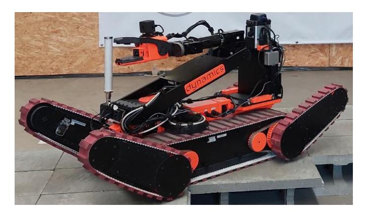
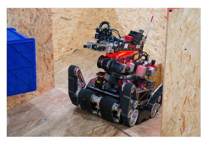
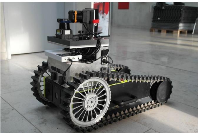
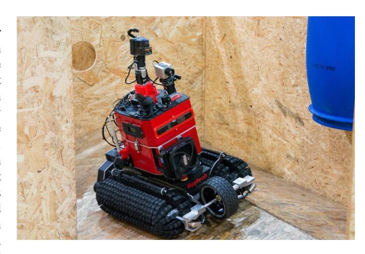
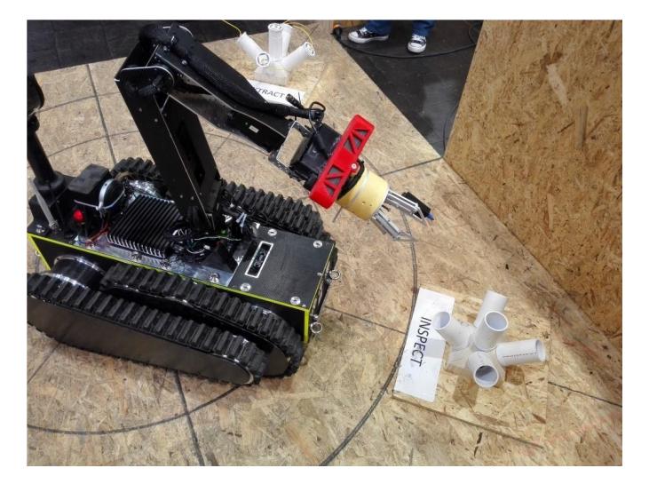
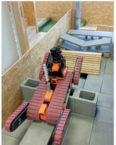
Building a robot which is supposed to attend the RoboCup Rescue League requires high degree of versatility and experience which makes it difficult to start in this competition from scratch. The new mechanical systems of the robot, see Fig. 1, including the robotic arm are assembled so far. Also the single modules such as the controller board and the peripheral system such as cameras and sensors are tested successfully on our other UGVs, called MARK, RED SCORPION, MARK Junior and COBRA, see Fig. 2, 3, 4 and 5. The main focus concerns the exploration of all different areas of the competition by generating a 2D/3D map and the detection of victims. The autonomous navigation on rough terrain is a challenging problem for mobile robots because it requires the ability to analyze the environment and make decision which parts can be traversed or need to be bypassed. Due to the developed design, the robots are fast and agile so it is able to handle all of the arenas. Another big goal is to develop a real-time, flexible and modular software and hardware robotic system with terrain traversibility analysis and 3D path planning for the new rescue robot, called HURRICAN.
A. Improvements over Previous Contributions
The locomotion of mobile robots in uneven terrain is one of the most difficult demands on the system. On one hand, as an outdoor robot it has to be fast and flexible on the other hand the vehicle has to deal with rough underground such as stones, gravel or stairs. Other important requirements are that the whole system is robust and consists of light weight construction to reduce the energy consumption. As shown in Fig. 2 MARK UGV has four active flippers, where every flipper is driven by two brushless motors, one motor drives the main pulley wheel, the second one is supporting the cantilever. The drive system basically consists of four pulley belts which are driven separately. Additionally the two belts (left and right side) and the middle belts can rotate individually. This is important for tasks like driving over uneven underground and climbing stairs. The body of the vehicle basically consists of an aluminum frame and the gaps, which are for reducing weight, are covered with carbon composite sheets. A novel tracked mechanism for sideways motion was developed, see Fig. 4. The robot can 'turn on a dime', or more correctly, it does not need to turn at all [1]. The unique Omni-Ball drive enables it to move in any direction in its plane of operation, and can make those moves almost instantaneously. The Omni-Crawler approach will definitely be a significant benefit in some applications that can be improved by its capabilities, and some applications that were previously impossible. Both systems were presented at RoboCup German Open 2013, 2014, 2015 in Magdeburg (GER) and RoboCup World Championship 2013 in Eindhoven (NED) and 2015 in Hefei (CHN). Other rescue robots are MARK Junior (for small robot applications), see fig. 3 and COBRA, see Fig. 5, were tested at the RoboCup German Open from 2016 -2019 and at the real nuclear facility in Zwentendorf. The team is designing a new tracked robot for the RoboCup 2022 which is described in the following sections:
II. SYSTEM DESCRIPTION
(Section header with subsections following)
A. Hardware
The RoboCup Rescue League requires the highest demands on the motor and sensory abilities of the robots. The robots are developed specially for the use in the field of security and emergency application. The preliminary aim is to build autonomous and teleoperated robots which are able to drive through an unstructured environment and search for victims. This includes generating a map of the environment and characterizing and locating victims as well as recognizing dangerous situation caused by fire and gas.
All our robots are equipped with a chain drive. One has also a flipper system to overcome bigger obstacles as described in the rules. The robots are connected to the operator station via 5 GHz WLAN (HURRICAN, COBRA, MARK Junior, MARK and RED SCORPION) and via 433 MHz (MARK Junior and COBRA). To generate a map from the scenario different 2D and 3D sensors are mounted on the robots.
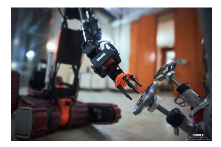
Locomotion: The new rescue robot called HURRICAN, see fig. 1, has been designed and built to be used in the first explorations of CBRNE scenarios and technical assistance. A modular payload robot and sensor system is realized [2] where camera and measuring systems can be quickly and easily adapted or replaced. The data can be transmitted by radio or fiber optic cable directly to the head of operations. With an optional manipulator small and light objects can be manipulated and moved. A multi-functional gripper system is developed to handle different objects, valves and doors, see Fig. 6. The new tracked vehicle has a four flipper system with additional belts around the chassis. This technology has proven itself in the last ones and enables all required test methods to be mastered best.
Batteries: The team is with commercial batteries such as batteries for drilling machines. For the new HURRICAN the team is using two MILWAUKEE M28 high voltage batteries to achieve an operating time of more than one hour.
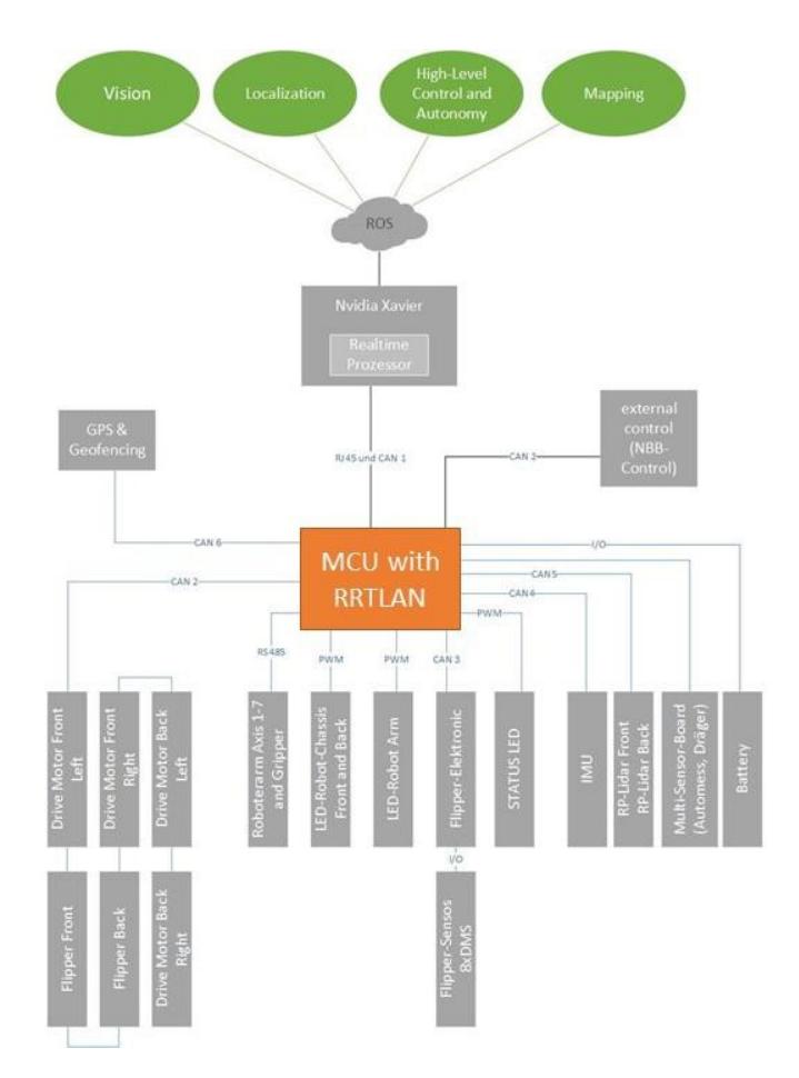
Electronics and Computation: The complete system design is shown in fig. 7. The previous control board, which was a self developed modular electronic system, has controlled all hardware components. For the new model the team implements a self-developed electronic and controller board. The comprehensive set of standardized components is perfect for implementing our flexible modular electronic concept. The heart of the PCB-boards is a ATxmega256A3U processor with multi-function I/O channels. The communication between the different PCB-boards are realized over a CAN-interface.
A real-time robot communication protocol stack with multithreading option (RRTLAN) is developed [3]. The new flexible communication protocol needs little micro-controller resources, so it can implemented even in tiny micro-controller with little memory. The protocol is based on the OSI/ISO reference model.
This separation simplifies the testing methods and gives the structure more flexibility. The intrinsic actuators, all motors for locomotion and for the robot arm, and all intrinsic sensors, as ultra-sonic sensors, absolute encoders, CO2-Sensor and IMU, are connected to the system, see Fig. 7. Other extrinsic sensors such as the Velodyne VLP-16, RGB and thermal camera are connected to embedded on-board computer NVIDIA Jetson AGX Xavier.
Manipulation: The main target of this project was to develop a robot arm for the rescue robot to grab and move things like small bottles or cubes with an approximately weight of 1 kilogram. The objects can be placed everywhere on the area and the arm should be able to get them also from plates in a height of up to 1.1 meters. To increase the stability and reduce the weight of the structure, materials like aluminum alloy and carbon are used. The compact arm consists of Dynamixel Pro motors with six axes, whereby axis 6 is endless and has great advantages especially when turning valves, see Fig. 8.
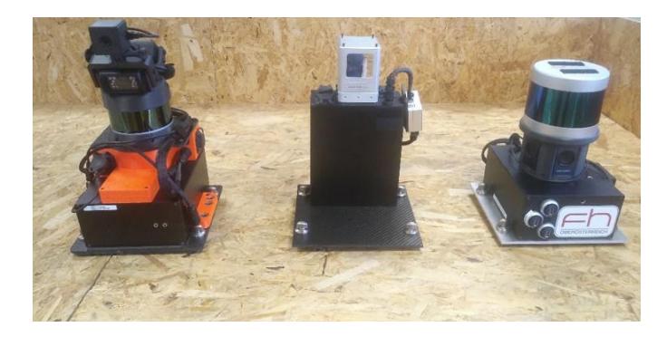
Sensors: Most robotic systems are equipped with different sensor modalities to achieve the best possible sensor coverage and redundancy. For the mobile rescue robot the following sensors are implemented: a.) Mapping: The UGV is equipped with different sensor types. For large scale mapping a Velodyne VLP-16 is used to map the environment. The new sensor system, see fig. 9, allows to install different LIDAR systems, depending on the application. The exploration tasks in particular require us to tilt the scanner by 30 degrees. This results in more field of view for this multi-line LIDAR and we can also detect the higher positioned object better. b) Object detection: An RGB (USB) in front of the gripper system is used for object detection and victim verification. A SeekPro thermal camera is mounted on top of the gripper for victim and heat source detection. c.) Localization: For the calculation of the track odometry we measure the translational and rotational speed of the vehicle. This odometry data is used for low level speed control. Additionally an IMU is implemented and fusioned with the other sensors to provide more robust robot localization in rough terrain. d.) Live stream: Several analog cameras which are connected to a video server provides real time view of the environment for the operator. e.) (NEW) Pressure distribution: A novel tactile sensor system (Fig. 10) is developed to get feedback from the ground and to improve the odometry data for tracked vehicles [4].
MARC Modular Adaptive Robot Concept: A novel modular and adaptable payload concept for plugging in sensor and actuator platforms such as 3D LIDAR and visual sensor systems and robot manipulator and gripper systems is developed, see fig. 9. Integration, programming and operation of heterogeneous robot systems (such as mobile manipulators or robots in a machine network) are very complex tasks for plant operators. Complex, heterogeneous, modular robot systems require manufacturer- and user-independent standardized interfaces based on open communication standards and information models in order to enable interoperability and integration. This shall reduce the effort for system integration and sensor calibrating significantly and provide a customized perception of the environment during certain work processes [2].
B. Software
Team Dynamics is using ROS Melodic. ROS - Robot Operating System is an open-source, meta-operating system for robots. It provides the services, which are expected from an operating system, including hardware abstraction, low level device control, implementation of commonly-used functionality, tools for visualization, message-passing between processes and package management. A basic ROS installation for RoboCup Rescue was developed at the workshop on Standard Robotic Software Architecture for RoboCup Rescue based on ROS in Koblenz, Germany (2011), ROS Robocup Rescue Summerschool in Graz, Austria (2012) and SSRR Summer School in Alanya, Turkey (2012). Refer to Table IV in the Appendix.
Low level control: For the communication between the electronic control system and motor control boards the CAN-Bus interface is used. Fig. 7 shows that most of the sensor and actuator electronic boards sending data via the CAN-Bus interface.
Communication protocol (video, commands, data): All components on the robot are connected via RJ45 (GigE). The analog cameras for teleoperating the robot are connected via BNC cables to the AXIS video server and provides real-time view during the mission. The RRTLAN [3] also provides almost trouble-free operation of the robot. At the DRZ Challenge 2021 network performance tests were performed, where e.g. packet loss, latency were simulated. Our entire robot concept was convincing and we had a constant connection to the mobile system.
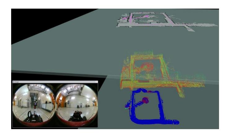
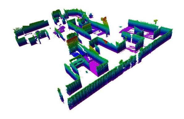
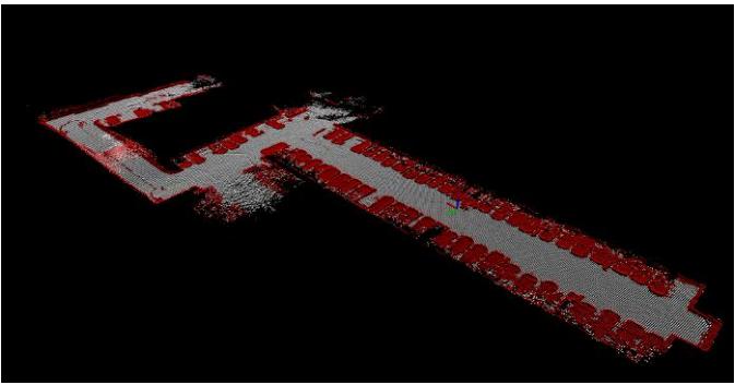
Mapping: The Simultaneous Localization And Mapping (SLAM) problem is solved in 3D by using a modified variant of LOAM [5]. We are developing and optimizing the mapping algorithm for the use with spinning LIDAR data and rough terrain locomotion. Fig. 12 shows 3D map output as octomap and Fig. 11 a multi-layered representation of the nuclear power plant (NPP) in Zwentendorf. The map can be manually or automatically annotated with information about victims and other objects of interest. It can be saved in the GeoTIFF format using the hector geotiff package. This package is available and documented as open source software as part of the hector slam stack [6] for ROS, which is widely used within the RoboCup Rescue League and beyond.
Path planning and autonomy: To better negotiate the increasingly difficult terrain in the rescue arena, the 3D spinning LIDAR data is used. This allows to acquire point clouds, build a 2.5D height map and classify the terrain into traversable and non-traversable grid cells. A path planning algorithm with adaptive Monte Carlo Localization (AMCL) [7] is implemented for simple waypoint navigation.
(NEW) Arm control and planning: The arm control and inverse kinematic is developed on the micro-controller boards. The operator can decide at the operator station which type of controller he wants to use. He can choose between the classic 2 lever control, master arm contoller (digital twin) or the 3D mouse. The Human-Robot interaction (HRI) is shown in Fig. 14.
(NEW) Traversibility and autonomous flipper control: The integration of semantic information derived from LIDAR and image segmentation for terrain modeling and the research for slip prediction from telemetry data are anticipated to significantly improve the mapping and traversibility capabilities in dynamic environments. Fig. 13 shows first results. We developed an autonomous flipper controller that can be implemented on a low-level controller without the use of an embedded system with high computing power. For this, we use 3D-data of a TOF-camera, project it onto a 2D-plane to estimate the slope of the terrain using linear least square regression. First results will be published in next time.
Victim and object detection: For the detection of victims, hazmat labels, different objects and QR-Codes an RGB camera and a SeekPro thermal is used. The object recognition algorithm is based on the YOLO5 and a database with labels was created. With the use of the OpenCV library and other open source tools it is possible to try out many different algorithms for computer vision.
C. Communication
For the communication between robot and operator station a BulletAC-IP67 is used which is operating on the 2.4 and 5 GHz band (802.11 a/n) with 100 mW power and a bandwidth between 54-300 Mbit/s. The wireless communication is used for both, the autonomous mode as well as for the remote control mode. The Ubiquity BulletAC-IP67 has the following features:
a.) Dual-Band Frequency The BulletAC-IP67 covers both 2.4 and 5 GHz radio bands, covering a wide range of frequencies that work well for both short and long-distance links.
b.) Output Power The Bullet AC-IP67 offers 21 dBm.
c.) Antenna: Alfa Omni-Antenne 2.4/5GHz 5/9dBi N-Stecker (AOA-2458-59-TM)
d.) For the competition we are using the SSID: RRL TeamDynamics
D. Human-Robot Interface
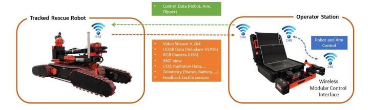
During the remote control mode most of our robot are controlled by a Microsoft Xbox 360 controller, which is connected to the operator station. Several cameras are mounted on the robot, one at the front and the other one at the rear side of the robot which gives images of the environment. Furthermore a thermal camera and standard cameras are mounted on the top of a robotic arm and provide live stream for the operator. A new remote control (Fig. 14) unit was developed (RCU 1000) which provide longer operation run-time and the unit is easy to handle and transport. Due to the rule changes and the weight limit of maximum 30 kg we developed a lightweight case with one laptop and one additional touch screens. A laptop is used to visualize all sensor data and to communicate with a new control system instead of the Xbox controller. The new controller unit facilitates the operation of the robot, in which several switches have been installed to turn on/off even semi-autonomous functions. The master arm model allows the intuitive and fast movement of the robot arm and can be used by any operator with little effort and time.
III. APPLICATION
(Section header with subsections following)
A. Set-up and Break-Down
For transporting the robot itself it can be packed into a move able case with wheels. All sensitive and expensive sensors such as thermal camera or laser range finder are packed separately in a case. The whole setup and breakdown procedure can be accomplished within less than 5 minute. The procedure includes starting up the operation station, controlling the network status, checking if the sensor are working properly and to make sure that all actuators in the initial position takes only one minute. For starting the mapping, autonomy and victim detection mode the robots are ready in three minutes.
B. Mission Strategy
In this year the focus of our research is reducing workload for operators and leveraging synergies between intelligent onboard systems and operators. The plan is to operate the maneuvering tasks MAN1, MAN2 and MAN3 autonomously. For all manipulation tasks we want to use our new implemented inverse kinematic for the robot arm. All other mission is pure teleoperation with a new autonomous flipper control. As in the previous competition participation, autonomous operation is the desired control modality. For complex mobility and manipulation tasks, autonomous operation benefits from the superior cognitive and sensory abilities of a human operator. In the future, the aim should be to simplify the operation of such complex robot systems for the operator.
C. Experiments
Competitions between team members are planned for the final month to train operators for the RoboCup championship. In the next few weeks, the team will evaluated the system in the test arena in a new laboratory building, where most of the NIST test methods [8] can be tested.
D. Application in the Field
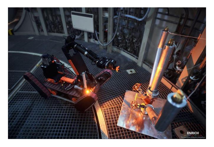
For mobile rescue robots it is very important to be able to maneuver through rough and uneven terrain. Especially during rescue missions or outdoor use the robot has to deal with hard environmental conditions. Therefore these rescue robots need a good drive concept to support the rescue units. At the moment usually chain or belt drives are used for teleoperated rescue robots. To improve the mobility these robots uses additional flippers. Such flippers are sometimes part of the drive and in a few cases only for stabilization. There are also drive concepts which consists out of rotatable and powered flippers. But these flippers rotation is limited due to the mechanical design. The team also participated for the IAEA - International Atom Energy Agency competition in Brisbane (AUS) 2017 and the EnRicH competition in a real nuclear facility, see fig. 15. In summary the team got practical application at RoboCup German Open, RoboCup Championships, EURATHLON, ELROB, ENRICH, IAEA-Robotics Challenge and the WRS - World Robot Summit. The strengths certainly lie in the intuitive operation of the robot. The only weakness is perhaps the low final speed and the not optimal grip of the belts. One of the most important components when dealing with mobile robots is reliable communication and easy operation without spending much time. Of course, the competitions help to improve the system, but a cooperation with first responders is inevitable. Finally, we also try as a team to research together with the emergency forces in workshops and exercises.
IV. CONCLUSION
The robotic system is suited to support rescue teams for allocating human victims, fire and gas in the case of a real disaster. It is supposed to support the rescue teams respectively replace humans in dangerous situations. The motion system, the robotic arm and the new rescue robots, which are mentioned above, allow to explore the operational area and detecting victims and dangerous situations. The team is in contact with fire fighting stations in the City Wels and with companies who are large manufacturers of fire fighting vehicles. With its wide range of municipal fire fighting vehicles we expect to force the development of our robot.
TABLE I ROBOT SYSTEM
| Attribute | Value |
|---|---|
| Name | HURRICAN |
| Locomotion | tracked |
| System Weight | 65kg |
| Weight including transportation case | 100kg |
| Transportation size | 1.2 x 0.8 x 0.75 m |
| Typical operation size | 0.8 x 0.5 x 0.4 m |
| Unpack and assembly time | 15 min |
| Startup time (off to full operation) | 5 min |
| Power consumption (idle/ typical/ max) | 60 / 200 / 800 W |
| Battery endurance (idle/ normal/ heavy load) | 240 / 120 / 60 min |
| Maximum speed (flat/ outdoor/ rubble pile) | 1.0 / 1.0 / 0.5 m/s |
| Payload (typical, maximum) | 6 / 20 kg |
| Arm: maximum operation height | 110 cm |
| Arm: payload at full extend | 1.5 kg |
| Support: set of bat. chargers total weight | 2 kg |
| Support: set of bat. chargers power | 1,200W (100-240V AC) |
| Support: Charge time batteries (80%/ 100%) | 10 / 20 min |
| Support: Additional set of batteries weight | 2kg |
| Cost | 25.000 EUR |
TABLE II OPERATOR STATION
| Attribute | Value |
|---|---|
| Name | RCU 1000 |
| System Weight | 20 kg |
| Weight including transportation case | 20 kg |
| Transportation size | 0.6 x 0.4 x 0.25 m |
| Typical operation size | 0.6 x 0.4 x 0.4 m |
| Unpack and assembly time | 1 min |
| Startup time (off to full operation) | 2 min |
| Power consumption (idle/ typical/ max) | 60 / 80 / 90 W |
| Battery endurance (idle/ normal/ heavy load) | 10 / 5 / 4 h |
| Any other interesting attribute | 2 screens |
| Cost | 3.000 EUR |
TABLE III HARDWARE COMPONENTS LIST
| Part | Brand & Model | Unit Price | Num. |
|---|---|---|---|
| Drive motors | Maxon RE 50 200 W | EUR 700 | 6 |
| Drive gears | Planetary Gearhead GP 52 | EUR 200 | 6 |
| Drive encoder | Encoder HEDS 5540 | EUR 100 | 6 |
| Motor drivers | EUR 500 | 6 | |
| Batteries | Milwaukee M28 | EUR 150 | 4 |
| Control system | EUR 3000 | 1 | |
| Computing Unit | NVIDIA Xavier | EUR 699 | 1 |
| WiFi Adapter | BulletAC-IP67 | EUR 150 | 1 |
| IMU | EUR 100 | 4 | |
| Cameras | EUR 200 | 4 | |
| Infrared Camera | Seek Thermal | EUR 400 | 1 |
| LRF | Velodyne VLP-16 | EUR 6000 | 1 |
| CO2 Sensor | EUR 50 | 1 | |
| Battery Chargers | M28C Charger | EUR 300 | 2 |
| 6-axis Robot Arm | EUR 12.000 | 1 | |
| Rugged Operator Station | EUR 3.000 | 1 |
TABLE IV SOFTWARE LIST
| Name | Version | License | Usage |
|---|---|---|---|
| Ubuntu | 18.04 | open | |
| ROS | melodic | BSD | |
| PCL | 1.8 | BSD | ICP |
| OpenCV | 3.4 | BSD | Victim detection |
| Yolo | 5 | BSD | Hazmat detection |
| LOAM | BSD | 3D SLAM | |
| RQT GUI | 0.7 | closed source | Operator Station |
APPENDIX A TEAM MEMBERS AND THEIR CONTRIBUTIONS
Raimund Edlinger - Mechanic, Traversibility, SLAM Michael Zauner - Electronic, uC-Programming Stefan Dumberger - Multi-Sensor-Fusion, SLAM Christoph Fols - Mechanical Design Dominik Zouhar - Object Detection Ulrich Mitterhuber - Terrain Segmentation Lisa Maria Moseneder - Motion Control Thomas Wogenstein - Autonomous Flipper Control Michael Anschober - Inverse Kinematic
ACKNOWLEDGMENT
The author would like to thank the University of Applied Sciences Upper Austria and the company TGW who are sponsoring the Team DYNAMICS.
References
[1] R. Edlinger, M. Zauner, and W. Rokitansky, "Intelligent mobility-new approach of robot mobility systems for rescue scenarios," in 2013 IEEE International Symposium on Safety, Security, and Rescue Robotics (SSRR). IEEE, 2013, pp. 1–5. [2] R. Edlinger and A. Nuechter, "Marc-modular autonomous adaptable robot concept," in 2019 IEEE International Symposium on Safety, Security, and Rescue Robotics (SSRR). IEEE, 2019, pp. 1–7. [3] R. Edlinger, M. Zauner, and W. Rokitansky, "Rrtlan-a real-time robot communication protocol stack with multi threading option," in 2013 IEEE International Symposium on Safety, Security, and Rescue Robotics (SSRR). IEEE, 2013, pp. 1–5. [4] R. Edlinger, C. Fols, R. Froschauer, and A. Nuechter, "Stability metrics and improved odometry prediction for tracked vehicles with tactile sensors," in 2021 IEEE International Symposium on Safety, Security, and Rescue Robotics (SSRR). IEEE, 2021, pp. 77–83. [5] J. Zhang and S. Singh, "Loam: Lidar odometry and mapping in realtime." in Robotics: Science and Systems, vol. 2, no. 9, 2014. [6] S. Kohlbrecher, J. Meyer, O. von Stryk, and U. Klingauf, "A flexible and scalable slam system with full 3d motion estimation," in Proc. IEEE International Symposium on Safety, Security and Rescue Robotics (SSRR). IEEE, November 2011. [7] S. Thrun, D. Fox, W. Burgard, and F. Dellaert, "Robust monte carlo localization for mobile robots," Artificial intelligence, vol. 128, no. 1-2, pp. 99–141, 2001. [8] A. Jacoff, R. Sheh, A.-M. Virts, T. Kimura, J. Pellenz, S. Schwertfeger, and J. Suthakorn, "Using competitions to advance the development of standard test methods for response robots," in Proceedings of the Workshop on Performance Metrics for Intelligent Systems. ACM, 2012, pp. 182–189. [9] R. B. Rusu and S. Cousins, "3D is here: Point Cloud Library (PCL)," in IEEE International Conference on Robotics and Automation (ICRA), Shanghai, China, May 9-13 2011. [10] P. Viola and M. Jones, "Rapid object detection using a boosted cascade of simple features," in Computer Vision and Pattern Recognition, 2001. CVPR 2001. Proceedings of the 2001 IEEE Computer Society Conference on, vol. 1, 2001, pp. I–511–I–518 vol.1.