UPM-SPQR Rescue Virtual Robots Team Description Paper
A. Valero, G. Randelli, P. de la Puente, D. Calisi, F. Matía, D. Rodríguez-Losada, D. Nardi
Department of System and Computer Science, Sapienza Università di Roma, Rome, Italy; Intelligent Control Group, Universidad Politécnica de Madrid, Madrid, Spain
http://sied.dis.uniroma1.it · http://www.intelligentcontrol.es/ · http://openrdk.sourceforge.net/
Abstract In this paper we describe the technical characteristics of the rescue system developed by UPM-SPQR Virtual Team for RoboCup 2009. This year, for the first time, the SPQR team, that has participated for years in the competition, will participate together with the "Universidad Politecnica de Madrid" as a joint team. This is the first time that "Universidad Politecnica" participates in the RoboCup. We analyse the whole architecture, also focusing on the new included features, such as the communication management and the 3D mapping. We also adopted the quadrotor, to give an aerial view of the scenario to the operator. We will show some preliminary results of a set of experiments analyzing the optimal ratio operator/robot in USAR missions.
Introduction
SPQR is the group of the Department of Computer and Systems Science at Sapienza University of Rome in Italy, that has been involved in RoboCup competitions since 1998 in different leagues (Middle-size 1998-2002, Four-legged since 2000, Real-rescue-robots 2003-2006, Virtual-rescue since 2006 and @Home in 2006). In 2007 the SPQR team got the third place in RoboCup Rescue Virtual Robots League in Atlanta (USA). All the research activities are carried out at the SIED Laboratory, which stands for "Intelligent Systems for Emergencies and Civil defense".
The UPM team is composed of people belonging to the Intelligent Control Group. The Intelligent Control Group is member of the Spanish Committee of Automation (CEA). Its research fields in mobile robotics include service robots, focusing on feature-based SLAM, autonomous navigation, and human-like behaviors. This is the first year the Intelligent Control Group will participate in Robocup, contributing with its research to the already developed software of the
The team's members are composed by Prof. Daniele Nardi and Prof. Fernando Matía as advisors, Daniele Calisi as team leader, Paloma de la Puente, Diego Rodriguez-Losada, and Alberto Valero.
In this paper we describe the technical characteristics and capabilities of the Rescue Robot prepared by the UPM-SPQR Rescue Virtual Robots Team for Robocup Rescue 2009 competitions in Austria (Graz). In the rest of the document, we will describe in the next two sections the system characteristics, focusing on the new HRI system we have developed, as well as the software architecture, based on our OpenRDK development framework. The following sections deal with the implemented exploration and mapping techniques, sensors equipment used in USARSim and finally some applications in real contexts.
2 Robotic Team and Software Architecture
(Section contains subsections only)
2.1 Team configuration
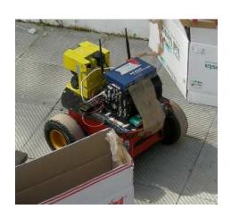
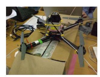
We will participate with a heterogeneous robotic team (Figure 1), which is composed of:
- three ground robots P2AT, equipped with a fixed SICK Laser Range Finder and an Hokuyo Laser Range Finder with a tilting platform (SIED), or a SICK mounted on a PowerCube Pan Tilt device (UPM group).
- one unmanned Aerial Vehicle (UAV) with an INS sensor and GPS sensor and the USARSim Victim Sensor. In the competition, due to the restrictions on the battery life of the League, we will use sonar for obstacle avoidance.
2.2 Software architecture
Our software is based on a multi-layered architecture. This architecture allows a high modularity of the software as well as a tight interaction with the operator, enhancing a supervisory and behavioral control of the robots.
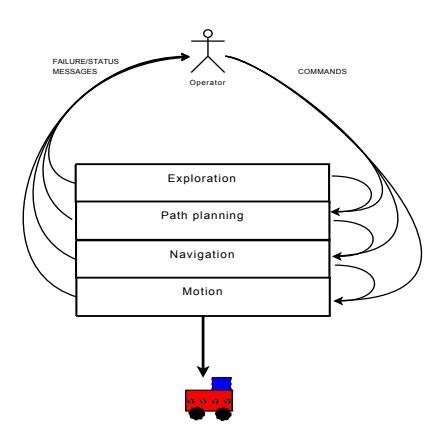
The architecture is shown in Figure 2. This architecture allows the operator to work in four autonomy levels:
- Autonomous Exploration. The robot decides where to go and tries to reach the desired point.
- Autonomous Navigation. The operator sets a target point that the robot tries to reach autonomously.
- Shared control. The operator sets a path that the robot tries to follow it.
- Tele-Operation. The operator takes full control of the robot.
Each autonomy level is managed by one layer of the architecture.
- Exploration Layer. Selects target points according to an exploration policy.
- Path Planning Layer. Finds a way to reach a point.
- Navigation Layer. Follows a path avoiding obstacles.
- Motion Layer. It is the interface among the software and the robot. It sends the speed and jog control values to the robot.
This architecture allows both a Behavioral and Supervisory control. In the Behavioral Control, the operator defines the operations of the robot by sending commands. On the converse, in the Supervisory Control the robot works in Full Autonomy; if one of the layers fails, a failure message will be sent to the operator, that will be able to overload this precise layer.
2.3 Exploration Layer
"Exploration and search" is a typical task for autonomous robots performing in rescue missions, specifically addressing the problem of exploring the environment and at the same time searching for interesting features within the environment. We model this problem as a multi-objective exploration and search problem and present a prototype system, featuring a strategic level, which can be used to adapt the task of exploration and search to specific rescue missions. Specifically, we use a State Diagram formalism that allows representing decisions, loops, interrupts due to unexpected events or action failures in a coherent framework. While autonomous exploration has been investigated in the past, we specifically focus on the problem of searching victims in the environment during the map building process [3]. Each robot computes the current target points and broadcasts them to all team mates, computes its utility function for all the tasks present in the system and broadcasts the function values to all other team mates. Each robot computes the best allocation of robots to targets and then execute the best task according to the chosen allocation.
2.4 Path Planning and Navigation Layer
The Path Planning and Navigation Layers are responsible of moving the robot towards the areas indicated by the Exploration Layer. It is implemented using the well-known two-level decomposition, in which a global algorithm computes a path towards the goal (Path Planning Layer), using a simplified model of the environment; this path is followed by a local algorithm (Navigation Layer), that generates the motion commands to steer the robot to the current goal. The global algorithm computes a graph that models the connectivity of the environment, modifying this model accordingly as the robot perceives information about the unknown environment: the path computation is thus reduced to a path search in a graph [2]. The local algorithm uses a variation of the well-known Dynamic Window Approach (DWA). The resulting trajectories are very smooth, thanks to the fact that the DWA generates only commands and trajectories that can be followed by the robot, considering kinematic and dynamic constraints.
2.5 Software Implementation
All our software is implemented in a framework developed by the SPQR group called OpenRDK [1]. OpenRDK is a modular software framework focused on rapid development of distributed robotic systems. The main characteristics of OpenRDK are:
- The main entity is a software process called agent. A module is a single thread inside the agent process; modules can be loaded and started dynamically once the agent process is running.
- An agent configuration is the list of the modules that are instantiated, together with the values of their parameters and their interconnection layout. It is initially specified in a configuration file.
- Modules communicate using a blackboard-type object, called repository, in which they publish some of their internal variables (parameters, inputs and outputs), called properties.
3 Human-Robot Interface
In our research we have been concentrating our efforts in developing a new HRI system able to manage the multi-robot-multi-user paradigm, and therefore to improve both the speed and quality of the operator's problem-solving performance and to improve efficiency by reducing the need for supervision. Our desktop interface is designed to control a robot in structured and partially unstructured environments dealing mainly with exploration, navigation and mapping issues. Its main purpose is to enhance the operator's performance of complex tasks, with a comprehensive overview of the robot location, surroundings and status.
3.1 Complex display
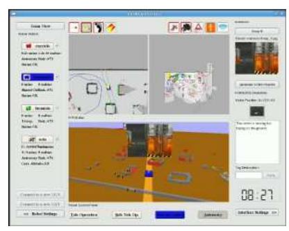
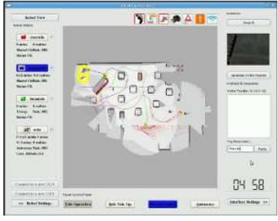
In the Complex Display (Figure 3(a)) there are two main panels:
Navigation Panel. The navigation panel consists of three displays: a Local View of the Map, a Global View of the Map giving a bird's eye view of the zone, and a pseudo-3D View giving a first person view. The robot is located within the map by a rectangle-symbol containing a solid triangle that indicates its direction. The 3D Viewer gives an egocentric perspective of the scenario by simply elevating the obstacles into 3D images.
Autonomy Levels Panel. It allows the operator to switch among four control modes: tele-operation, safe tele-operation, shared control and autonomy. In the safe tele-operation mode the system prevents the robot from colliding with obstacles, limiting the speed. In the shared control mode the operator sets a target point for the robot by directly clicking on the map, which the robot tries to reach.
3.2 Team View Display
The Team View Display (Figure 3(b)) includes a comprehensive view of all robots, providing an aerial point of view. This view allows the operator to supervise the team operations and send commands to each single robot. This view can be zoomed in and out.
3.3 Pseudo 3D Display
The pseudo 3D display is equivalent to the one shown in the Complex Display. It is specially useful when there are big errors on the calculated map. At this moment the video feed-back becomes the main source of information, while the maps are practically useless. This view shows the video retrieved from the camera and the obstacles read by the laser range finder.
4 Map Generation and Printing
To build a consistent global map, we implemented a centralised coordinated SLAM approach that merges the local maps from all robots, while each robot builds its own local map integrating LRF output and encoder information. As for the UAV, at the moment it doesn't contribute to the map generation, because the Hokuyo laser is used for obstacle avoidance. Moreover, because of limited computational resources, it's impossible to have on-board image processing. So the UAV has a role only in exploration and victims detection tasks, especially in areas with bad mobility conditions for the UGVs. The map is finally converted into a bitmap image. On such a map the identified victims can be annotated to produce a final report. Each robot also maintains a local map autonomously built. Therefore, if a communication breakdown interrupts the link between one robot and the central station, the robot is still able to perform its tasks reasoning on its local map.
5 The UAV role
In outdoor SAR operations, operators perception of remote environments often relies on the video feeds from the camera(s) mounted on the robots. The UAV generally provide exocentric (perspective from outside the environment) views of the problem space (e.g., a train station after a gas explosion) while the unmanned ground vehicles (UGV) present viewpoints that are egocentric (perspective from within the environment) and immersed in the environment. The ideal view depends on the task; overall awareness and pattern recognition are optimized by exocentric views whereas the immediate environment is often viewed better egocentrically. In last year competition (Suzhou 2008) we used for the first time UAVs in combination with UGVs for finding victims.
6 Innovations
This year two main innovations will be implemented: 3D Mapping and Communications Management.
6.1 3D Mapping
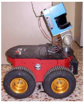
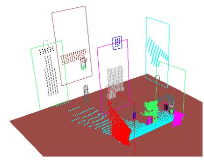
The 3D mapping strategy that we plan to use for the competition is a feature-based maximum probability algorithm. The segmentation process is carried out employing a combination of computer vision techniques that offer remarkable advantages [4]. Our idea is to create a 2D projection of the 3D map so that holes, stairs and whatever obstacles, detected on the ground or above, that may interfere with the robot navigation, can be avoided. Semantic information about the aforementioned objects might eventually be added into the competition final report. To collect the 3D data, the PM group has got a P3AT robotic platform equipped with a pan-tilt unit with a range scanner laser SICK LMS200 mounted on top (Figure 4(a)). Our virtual robot will instead use a horizontally positioned SICK laser to perform 2D SLAM and an additional, nodding, Hokuyo laser on top of a pan-tilt wrist to obtain the 3D data. Figure 4(b) shows an example of a segmented 3D point cloud.
6.2 Communications Management
We are working on the creation of a MANET (mobile ad hoc net-works) structure among the robotic platforms. A MANET is constituted by mobile devices that communicate with one another via wireless links without relying on an underlying infrastructure. This distinguishes them from other types of wireless networks as, for example, cell networks or infrastructure-based wireless networks. To achieve communications in a MANET, each robot acts as an endpoint and as a router forwarding messages to the devices within radio range, to communicate all the information retrieved by the robots to the Base Station.
7 Practical Application to Real Rescue Robots
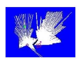
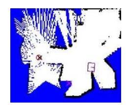
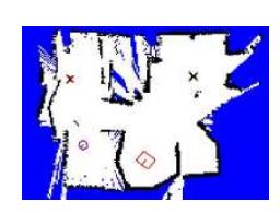
The whole system has also been implemented and tested on real robot units. We validated our approach with a P2DX equipped with an Hokuyo Laser Range finder, and a P2AT equipped with a SICK LRF. The experiments have been conducted in the arena set up in our lab (Figure 5 shows the maps at three different times during the mission).
8 Conclusion
Among the future tasks that we have been thinking of we are focusing on the integration management into the operator GUI. We are also working on a full 3D localization and mapping system, so that irregular terrains, can be more precisely mapped. As for the UAVs, we have been analysing scenarios where UGVs have the full equipment for victim recognition, while the aerial vehicle just a partial one. From last year experience the interface has been improved, providing a better integration of the operator with the robot software. One main objective as future work is to improve our map merging subsystem using a partially distributed algorithm, rather than a centralized one.
References
- D. Calisi, A. Censi, L. Iocchi, and D. Nardi. OpenRDK: a modular framework for robotic software development. In Proc. of Int. Conf. on Intelligent Robots and Systems (IROS), pages 1872–1877, September 2008.
- D. Calisi, A. Farinelli, L. Iocchi, and D. Nardi. Autonomous navigation and exploration in a rescue environment. In Proceedings of IEEE International Workshop on Safety, Security and Rescue Robotics (SSRR), pages 54–59, Kobe, Japan, June 2005. ISBN: 0-7803-8946-8.
- D. Calisi, A. Farinelli, L. Iocchi, and D. Nardi. Multi-objective exploration and search for autonomous rescue robots. Journal of Field Robotics, Special Issue on Quantitative Performance Evaluation of Robotic and Intelligent Systems, 24:763– 777, August - September 2007.
- Paloma de la Puente, Diego Rodríguez-Losada, Raul López, and Fernando Matía. Extraction of geometrical features in 3d environments for service robotic applications. In Hybrid Artificial Intelligence Systems, Third International Workshop, HAIS 2008, Burgos, Spain, pages 441–450, 2008.