Kaobotics: The Adult-Sized Humanoid Robot Team Description Paper
Kuo-Yang Tu, Chin Hung Tsai, Chia He Lee, Chen Yu Chiu, Wun Jian Wei
Institute of System Information and Control, National Kaohsiung First University of Science and Technology
Abstract This paper discribes the first adult sized humanoid robot designed by NKFUST. In general, control of a big humanoid robot is hard by only using join torque. External sensors used to monitor its body dynamics are important for big humanoid control. In our current focus, both force sensor for static behavior and motion sensor for dynamic behavior are designed and implemented for a dynamic motion balance humanoid robot. The objective of the current study is to develop the strategy of dynamic motion balance for adult-sized humanoid robots. The mechanical design issue of the big humanoid is described. In addition, the use and installation of both force and motion sensors are included
Introduction
The leg structure makes humanoid robots easy to fall down. To maintain its stability during walking in dynamic situation requires a good mechanical design, extra sensors such as force sensors and accelerometers to acquire the information of its move. Many humanoid robots have been developed, such as ASIMO by Honda [1], WABIAN 2R by Waseda University, HUBO KHR-3 by KAIST [2] and QRIO by Sony. Hkatib proposed torque-position transformer for enough torque to steer ASIMO [3]. However, it is hard for only using joint torque to control a big humanoid robot.
Humanoid robots are open-chain structure that makes their postures hard to be estimated by joint angles. Even if using successful algorithms estimate humanoid robot posture, its error is usually huge by accumulative inherence. Hence, accelerometers and gyroscopes are usually designed to estimate the absolute posture of a humanoid robot. The other function of accelerometers and gyroscopes are to measure the walking dynamics of humanoid robots. Especially, the heave dynamics of a big humanoid robot is hard to control in open loop. In this paper, the big humanoid robot designed by installing accelerometers and gyroscopes for closed-loop control is proposed.
Kinematics of the Big Humanoid Robot
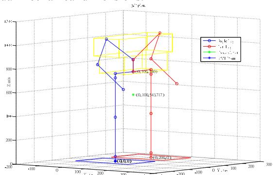
Fig. 1 is the structure of the humanoid robot in a initial post. Note that it is drawn by MATLAB in actual mechanical dimensions.
In traditional method, humanoid robots usually derive forward kinematic equations in geometric space. Although the solution of using geometric space is comprehensive, D-H rule that is easy to derive robot dynamics is engaged in this paper.
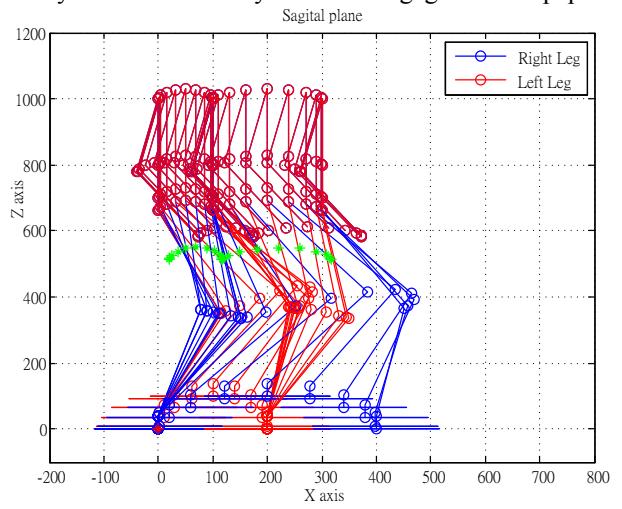
The forward kinematic equation is used to derive inverse kinematics of the humanoid robot. Both forward and inverse kinematics are demonstrated by calculating the humanoid robot for a walking step. Fig. 2 shows the stick diagram of the humanoid robot for a walking step. This result demonstrates the correction of both forward and inverse kinematics of the humanoid robot.
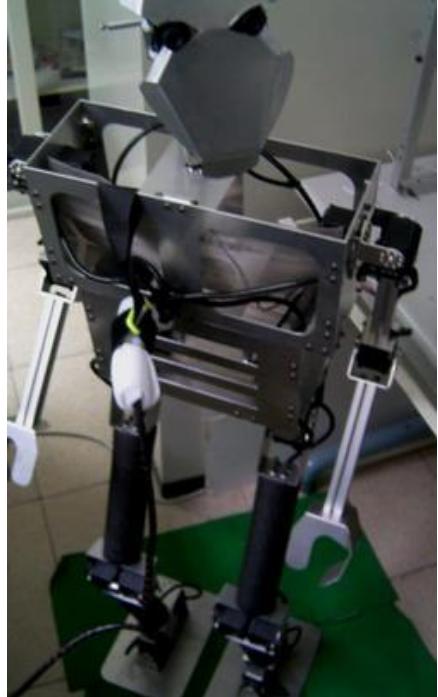
In the adult-sized humanoid robot, some joints make use of two motors to steer simultaneously for much torque. The joints that use two motors are the ankle and knee at x direction and the hip at y direction. The motors used in the big humanoid robot are twenty in total. In addition, its height is 1.3 meters, and its weight is 6.8 Kg. Such big humanoid robot is hard to control by using open loop control. Therefore, the accelerometers and gyroscopes are designed and dynamic sensors, but the force sensors are designed as static sensors for the humanoid control. Both dynamic and static sensors feedback the walking dynamics to form the closed-loop control during the walking gait.
Sensor Installation
Four strain gauges build the force sensors designed on the bottom of soles.
Let a measure set be {(xi, yi), for i = 1, …, n}, and a strength line y = ax + b approximate the measured set. Then the error can be defined as
$e_i = y – y_i = (ax_i +b) – y_i$
Thus, the sum of square error is
$$E = \sum_{i} e_{i}^{2} = \sum_{i} [(ax_{i} + b) - y_{i})]^{2}$$
The minimum of mean square error is to solve
$$\begin{cases} \frac{\partial E}{\partial a} = 0, \ \frac{\partial E}{\partial b} = 0. \end{cases}$$
In order to have the minimum of square error, the parameters a and b can be solved by the following lemma.
Lemma 1: To minimum of E in Eq. (1), the parameters a and b satisfy
$$a = \frac{\begin{vmatrix} XY_{xy} & X \ Y & n \end{vmatrix}}{\begin{vmatrix} X^2 & X \ X & n \end{vmatrix}}$$
$$b = \frac{\begin{vmatrix} X & n \ X^2 & XY_{xy} \ X & Y \end{vmatrix}}{\begin{vmatrix} X^2 & X \ X & n \end{vmatrix}}$$
where $X = \sum_{i} x_{i}$, $Y = \sum_{i} y_{i}$, $X^2 = \sum_{i} x_{i}^2$, $XY_{xy} = \sum_{i} x_{i}y_{i}$, and n is the numbers of the measure set.
Proof: ignored.
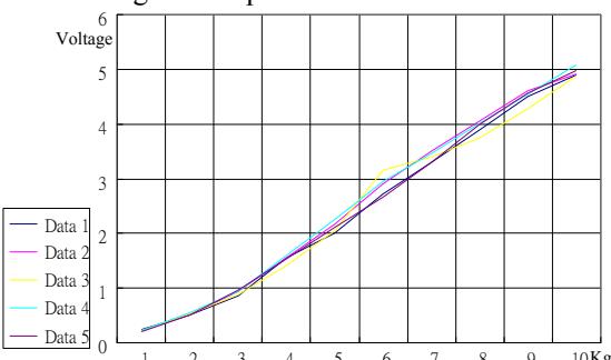
Every one force sensor should be calibrated before using. The calibration examines five tries from 1 to 10 Kg. Fig. 5 is the results of five tries. These examination data will use Eqs. (3) and (4) to find the parameters a and b that construct the equation of force sensor.
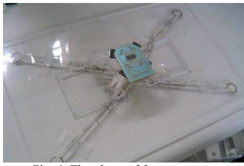
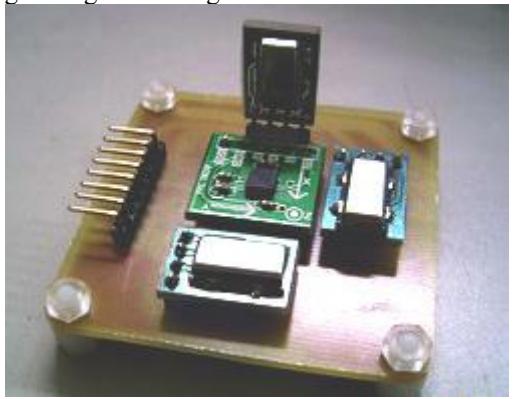
About the dynamic sensor, one three-axis accelerometer and three one-direction gyroscopes are designed together. Fig. 6 is the module of the sensor.
Walking Patterns
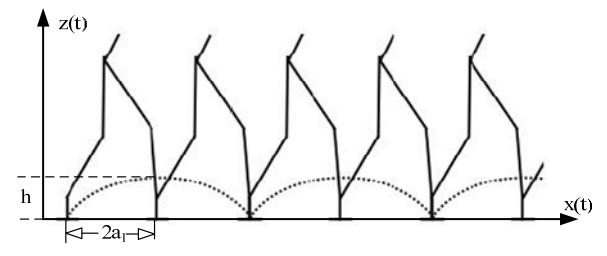
The humanoid robot employs cycloid equation as walking pattern. The cycloid equation depicted as Fig. 7 for the humanoid robot walking pattern expresses one step walking as follows (for $0 \le t \le t_1$):
$$x(t) = \frac{a_1}{\pi} \left( 2\pi \frac{t}{t_1} - \sin 2\pi \frac{t}{t_1} \right)$$
$$z(t) = \frac{h}{2} \left( 1 - \cos 2\pi \frac{t}{t_1} \right)$$
where $t_1$ is the period of one walking step, $a_1$ is one half of a walking stride, and h is the height of the walking stride.
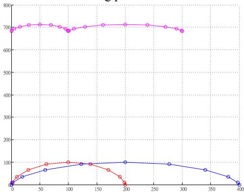
Two cycloid equations designed for sole and waist trajectories form the walking pattern of the humanoid robot. After the inverse kinematics solved from forward kinematics, two cycloid equations can solve the trajectories of all joints. Fig. 8 shows the sole and waist trajectories. Note that the red curve is the half trajectory for the humanoid robot in initial walking posture.
Summary of our adult-sized humanoid robot
So far, our team did the research for an adult-sized robot as follows:
- Motion energy analysis during walking [4];
- Using acceleration sensor to measure human walking energy [5];
- A big humanoid robot design and implementation [6].
References
- Honda homepage, http://www.honda.co.jp/ASIMO.
- http://mind.kaist.ac.kr/3re/research.htm
- O. Hkatib, P. Thaulad, T. Yoshikawa, and J. Park, "Torque-Position Trnsformer for Task Control of Position Conlled Robots," 2008 IEEE Intern. Confer. On Robotics and Automation,", pp. 1729-1734.
- Kuo-Yang Tu and Mi-Shin Liu, "A Study on the Motion Energy of a Biped Robot manipulated by different Degree of Freedoms," CIRAS 2008.
- Kuo-Yang Tu and Wei-Cheng Lee, "Analysis and Study of Human Joint Torque and Motion Energy during Walking," Proceedings of 2009 CACS International Automatic Control Conference, Nov. 27-29, 2009.
- Kuo-Yang Tu and Ming-Fang Tsai, "NeiDau: a big robot with force and motion sensors," 1st Austrian - Taiwanese – Canadian Workshop on Intelligent Robots and Computer Vision, Vienna, 2010.