Tsinghua Hephaestus 2013 AdultSize Team Description
Mingguo Zhao, Yu Wang, Yang Liu, Yunpeng Su, Jiaming Wu, Yining Li, Yifan Hou, Rundong Wang
Tsinghua University, Beijing, China
Abstract This document describes the specifications and functions of the humanoid robot THU-Strider, developed by team Tsinghua Hephaestus as a platform for research in bipedal locomotion, robot self-localization. The robot will be used to participant in Humanoid League(AdultSize) of RoboCup 2013
1 Introduction
The Tsinghua Hephaestus is a RoboCup team running at Dept. of Automation, Tsinghua University, China, since 2004. Our current research interest is focused on bipedal locomotion[1][2][3][4], robot self-localization[5][?]. Our first Humanoid League participant experience is in the RoboCup2007. In RoboCup2008, our TeenSize team got the 2nd place. Moreover, we got the 3rd in Robocup2009-2011 in TeenSize or AdultSize. Last year, we got the 2nd place in AdultSize again. We have been getting prepared well for the coming Robocup2013. THU-Strider is an AdultSize humanoid soccer robot developed as a platform for Tsinghua Hephaestus RoboCup team in RoboCup 2013. A passive dynamic walking based powered walking-Virtual Slope Walking is developed for gait generation. The control system of this robot is developed using NI single board RIO and LabView software. This document will give a general view of the robot.
Tsinghua Hephaestus commits to participate in RoboCup 2013 in Eindhoven, Netherlands and to provide a referee knowledgable of the rules of the Humanoid League.
2 The Robot Design
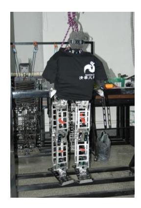
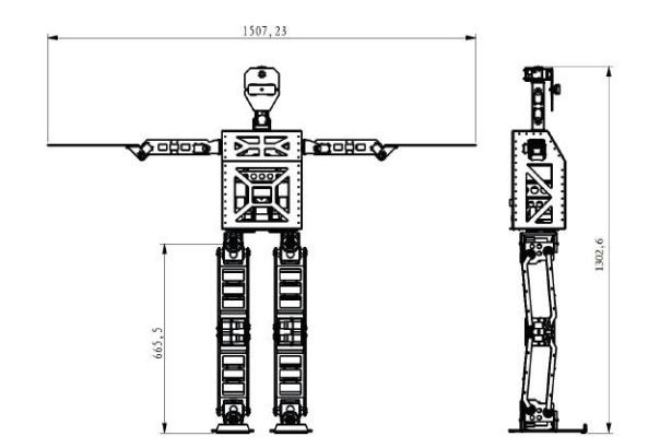
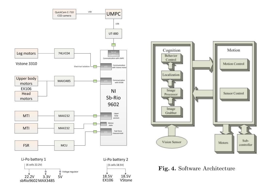
Fig.1 shows our THU-Strider robot in practice. The robot has a height of 1302.6 mm, and weights 18.10 Kg, including batteries. The detailed dimensions are shown in Fig.2. The robot has 18 DOFs: 5 in each leg, 3 in each arm, 2 in the head. For THU-Strider, 10 Vstone V3310 servo motors are used as actuators for legs and 8 Robotis EX106+ for arms. We use NI Single Board RIO-9602 as the motion controller. And use a Sony-UMPC as the main controller, with one USB port to motion-controller and another to the head camera. One Logitech QuickCam C-710 CCD camera is used as the vision sensor located in the robot head. Buttons and LEDs, located on the back, are set to control and indicate the robot state. The motors on upper body are connected in series on a RS-485 bus and lower body (leg) motors are connected in series on a LVTTL bus. The details of the control system are shown in Fig.3.
3 Software Architecture
The software consists of two processes, Cognition and Motion. The two processes run in parallel and interchange data through a message queue. Cognition is responsible for information perception, self-localization and behavior decision, while Motion is responsible for gait planning and motor controlling. Each process is divided into several modules according to their function. Modules are arranged so that they are independent to each other. Module configurations and data flows are shown in the Fig. 4.
Image Grabber grabs images from the vision sensor and generates related information of the image and the pose of the camera.
Image Processor processes the incoming images grabbed by Image Grabber, and yield information needed for Localization and Behavior Control.
Localization: implements the Particle Filter localization algorithm, manages position information of robots and the ball, as to be used by Behavior Control.
Behavior Control controls the game process and makes behavior decisions.
Motion Control manages all the actuators of the robot, and controls locomotion or any other action of the robot according to the requests from Cognition.
Sensor Control manages other sensors, and interacts with the Sub-Controller.
4 Vision
We use a camera as vision sensor, which has two tasks: object recognition and localization. The object recognition process is based on the result of color segmentation. However, not the whole image is used to retrieve features for object recognition, the image is scanned along a grid, thus to save computational expense.
4.1 Vision Sensor
We employ a Logitech QuickCam C-710 web camera, whose field of view is about 51◦ × 37◦ , and the robot is able rotate its head to extend the sight. The camera is connected to the main controller via USB 2.0, and outputs real-time image series with a resolution of 320 × 240 of 25 fps.
4.2 Color Segmentation
We now have the original image (320 × 240 RGB), which costs about 230KB of RAM resource. Color Segmentation classifies all of the possible colors in the color space to 16 groups. This classification not only provides information for objection recognition, but also reduces the cost of image storage and processing.
4.3 Object Recognition
Feature Extraction Features, a characteristic series of colors or a pattern of colors, are used for object recognition, e.g.,a sequence of some orange pixels is an indication of a ball. Objects are distinguished by their shapes and colors, and the colors are already classified. Fortunately the objects in RoboCup are all simple geometries, we employ several detectors to extract them.
Algorithm Framework Scan line is moving from one side of the image to another, and during the process it will find clusters of special colors. And the process will end if no more special colors appear. Then each cluster of special colors calls for a corresponding detector (object recognition) in related areas. For instance, consecutive orange pixels call the process of ball detector.
Ball Detector Firstly we use Breath First Search (BFS) in order to find candidate regions of the ball. Secondly, for each candidate region, we sort points in the region by polar angle to find points on the borderline. Thirdly, also for each candidate region, the convex hull of the region is calculated and a certain number of points in the convex hull are randomly sampled many times, and each time a circle is fitted with these points and the fitting error is calculated. The circle with the least error is recorded, and if the error is less than a given threshold, this region is accepted as a ball. The result of the Ball Detector is shown in Fig.5.
Goal detector Since goal is a reasonably large rectangle area with yellow pixels, firstly we find such areas. Secondly, we use an algorithm based on moment-method just like linear regression. Then we search the goal from the bottom of it and check the minimum eigenvalue of inertia matrix simultaneously. Stop while the eigenvalue becomes greater suddenly.
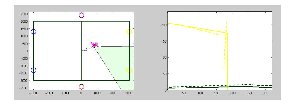
Field Line detector Lines include field lines and goal lines, and their detections are similar. So moment-method is also used in field Line detector: we start searching from a random white point, and use linear regression simultaneously. Stop until descending of quality of regression. Then we use a hypothesis inference to find all points on the line. The complexity of all the algorithms is O(n) (n is the number of points for a special color). The result of recognition is shown in Fig. 6. There are many classic methods (e.g. Canny Edge Detector) for line detection in the context of computer vision and we also draw on ideas from them


5 Localization
After object recognition, we use the well-known Particle Filter algorithm for self localization. We use 400-1000 particles to estimate the distribution of complete state f(x, y, θ) of robot. Each point (with direction) in the Fig.7 represents a state. If the distribution is reliable, we calculate the average state of robot, and this information is passed on to behavior control module together with the results of object recognition. Sometimes robot only needs the direction or position, in this circumstances we calculate the margin distribution of it. (always a margin distribution).
6 Behavior Control
The data provided by the sensors and location modules is used to plan a more complex behavior series. And the module of Behavior Control takes the charge of this task. The main task is separated into subtasks until they can be described as a set of basic behaviors which can be executed by the robot. All this is done by a hierarchical state machine described in XABSL (Extensible Agent Behavior Specification Language). The basic motion actions are transferred to and interpreted by the motion module, while other basic actions are processed in further modules.
It can output the following variables: 1) A motion request of basic behaviors to inform the motion module the robot's next action. 2) A head motion request of head mode to inform the motion module the robot's next head action. 3) 3 LED's state. An XABSL behavior specification is comprised by a set of behavior modules called options and a set of different simple actions called basic behaviors. Each option consists of numbers of states or subordinate options. Each state has two parts of information, decisions and actions. Decisions describe the conditions whether to jump out or stay in the current state according to the input variable, while the actions consist of the outputs such as the basic behaviors, LEDs etc.
7 Gait Planning
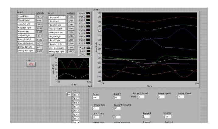
We divide the motion of one step into many frames. To generate the gait, we design some of the frames which are called key frames, and get the rest frames by connecting the key frames with smooth sinusoids.The implementation of forward walking is applying Virtual Slope Walking in the sagittal plane with the Lateral Swing Movement for lateral stability[1]. The forward walking speed of THU-strider is 0.6cm/s. The sideward walking and turning is realized by carefully designing the key frames. All of the above gait is generated by connecting the key frames with smooth sinusoids. By merging the translational movements with the rotational movements, Stepper-Teen is able to perform omnidirectional walking.
Gait planning is mainly done on SingleBoard RIO9602. When we get basic motion request from upper module, motion is translated into instructions for each joint actuator. Instructions of each frame are sending out in a row via communication bus to make robot move as expected. This module is programmed in NI LabVIEW.
8 Kicking
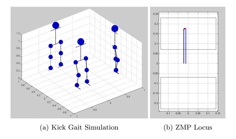
The design of kicking movement is based on the ZMP theory. The process can be briefly divided into three steps: firstly, set the position and speed of a part of motors with a preset motion; secondly, set the desired ZMP trajectory, by which a close form restriction of all motors would be got; finally, solve those restrict functions to get the position and speed of the other motors. The result is the speed and position for each motor. To actualize this algorithm naturally, the kicking movement is divided into several parts, then each part is divided into many frames to be executed. A Matlab program is designed to do the calculation frame by frame. After the calculation, one feasible strategy of kicking movement based on ZMP will be got as a matrix, each line records the position of motors at a certain time.
9 Conclusion
Our AdultSize robot THU-Strider is a self-autonomous humanoid robot, with 1 camera and 18 actuators integrated on body, controlled with a UMPC-SingleBoardRIO system.
In this paper we present the specifications and functions of THU-Strider, as well as some related works on vision, localization and gait planning.
10 Commitment
Tsinghua Hephaestus commits to participate in RoboCup 2013 in Eindhoven, Netherlands and to provide a referee knowledgable of the rules of the Humanoid League.
References
- M. Zhao, J. Zhang, H. Dong, Y. Liu, L. Li and X. Su, Humanoid Robot Gait Generation Based on Limit Cycle Stability, In the proceedings of the RoboCup Symposium 2008., LNAI 5399, pp. 403-413, 2009.
- M. Zhao, H. Dong and N. Zhang, The instantaneous leg extension model of Virtual Slope Walking, IEEE/RSJ International Conference on Intelligent Robots and Systems, pp. 3220-3225, Oct. 2009.
- H. Dong, M. Mingguo Zhao, J. Zhang andN. Zhang, Hardware design and gait generation of humanoid soccer robot Stepper-3D, Robotics and Autonomous Systems, vol. 57, no. 8, pp. 828-838, 2009.
- H. Dong, M. Zhao and N. Zhang, High-speed and energy-efficient biped locomotion based on Virtual Slope Walking, Autonomous Robots, vol. 30, no. 2, pp. 199-216, Jan. 2011.
- Y. Cai, M. Zhao, Z. Shi and W. Xu, "An Experimental Comparison of Localiza tion Methods in Robocup Four Legged League", Robot, 2007, Vol. 29, No. 2, pp167-170.
- Z. Liu, M. Zhao, Z. Shi and W. Xu, Multi-robot Cooperative Localization through Collaborative Visual Object Tracking, In the proceedings of RoboCup 2007 Symposium, LNAI 5001, pp. 41-52, May. 2008.