The Sweaty 2014 RoboCup Humanoid Adult Size Team Description
Armin Dietsche, Klaus Dorer, Michael Fehrenbach, Waldemar Frei, Stefan Glaser, Sabine Hirtes, Ulrich Hochberg, Ibrahim Ismail, Nils-Malte Jahn, Rudi Kirn, Raphael Koger, Mathias Niederhofer, Mahdi Sadeghi, Manuel Scharenberg, Igor Tropmann, Efstratios Tziallas, Bernd Waltersberger, Michael Wülker, Sneha Venkataramana
University of Appl. Sci. Oenburg, Germany.
Abstract This paper describes the new Sweaty humanoid adult size robot trying to qualify for the RoboCup 2014 adult size humanoid competition. The robot is built from scratch to eventually allow it to run. One characteristic is that to prevent the motors from overheating, water evaporation is used for cooling. The robot is literally sweating which has given it its name. Another characteristic is, that the motors are not directly connected to the frame but by means of beams. This allows a variable transmission ratio depending on the angle.
Introduction
One main research goal with Sweaty will be the improvement of bipedal walking algorithms eventually allowing the robot to run. Also new approaches are taken to increase the torque of motors by water evaporation. 3D printing has been used to construct very low weight components for joints. Another specialty of Sweaty is, that its motors are not directly moving the joints, but use levers. Advantages are that the motors are not experiencing the full weight of the robot and that the force of the servos is better utilized. The levers are arranged in a way that there is a variable transmission ratio: small deviations from the zero moment points of the joints allow quick movements (with medium torque), whereas at large angles high torques can be realized (but the speed is reduced).
The rest of the paper is organized as follows: section 2 describes Sweaty and its components in more detail. Section 3 is focused on the manufacturing of the robot. Section 4 describes the software that controls the movement and simulation of Sweaty, section 5 concludes with some formal statements on refereeing, previous achievements and software usage.
2 Robot
Sweaty is designed to have a height of 140 cm and a weight of 10.1 kg. 19 DOF are installed. Further 5 degrees of freedom planned to bend the backbone and for the hands. Two EIA-485-buses are installed to provide the communication with actors and sensors. For the main computing we use an Odroid-XU, which is connected via USB to our communication controller. Details are described in section 2.4 The communication controller is of our own design, as well as the other controllers we use. For image processing we also use the Odroid-XU. Support for joints, motors and sensors are made of aluminium which is sintered by means of a prototyping machine. The skeleton is made of composite carbon. A main focus of interest is to provide a robot that is in principal capable of running-like motions.
2.1 General design
Sweaty is designed to have a height of 140 cm and a weight of 10.1 kg. 19 DOF are installed. Further 5 degrees of freedom planned to bend the backbone and for the hands. Two EIA-485-buses are installed to provide the communication with actors and sensors. For the main computing we use an Odroid-XU, which is connected via USB to our communication controller. Details are described in section 2.4 The communication controller is of our own design, as well as the other controllers we use. For image processing we also use the Odroid-XU. Support for joints, motors and sensors are made of aluminium which is sintered by means of a prototyping machine. The skeleton is made of composite carbon. A main focus of interest is to provide a robot that is in principal capable of running-like motions.
There are big challenges to overcome before a robot can achieve running-like motions [SM1]: 1) the required torques for dynamic running are very high 2) stability control of fast running cannot be achieved by conventional robotics control concepts and 3) the distribution of internal torques are to be identied.
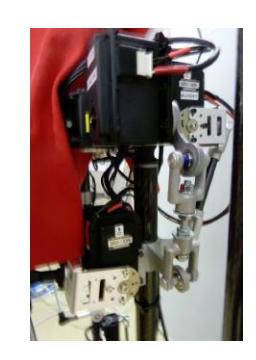
In a rst step we focus on the rst issue to provide suciently high torques: new concepts for a light-weight design are under research (composite compound materials and manufacturing with a rapid prototyping machine) and in addition the mean power of the actuators is increased by evaporative cooling. And, by the way, humans are also cooling their muscles by evaporative cooling - sweating. The motors are connected by means of beams to allow quick movements and a variable transmission ration depending on the angle.
Another characteristic is, that the motors are not directly connected to the frame but by means of beams. This allows a variable transmission ratio depending on the angle.
In later steps we will try to optimize control algorithms and optimize energy and momentum issues.
2.2 Thermodynamics
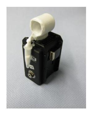
The torque of conventional actuators at a given mass is limited by the heat dissipation. An increase of heat transfer automatically helps to increase the mean torque of an actuator as long as the magnetic saturation is not reached. This is the case for most of the conventional actuators. For example, one of the possible actuators (Dynamixel MX-28R) is powered by an RE-max-17-motor manufactured by Maxon. The thermal resistance between housing and air is 35 K/W, and there is an additional thermal resistance due to the body of the actuator. The thermal resistance between the coils and the housing of the motor is only 12 K/W [ma1]. Reducing the thermal resistance between air by two thirds would therefore double the allowed heat dissipation. This reduction can be realized by conductive heat transport to a wet surface, where water is evaporated, see Fig. 2.
The mentioned actuator has a stall current of 1.7 A and a stall heat dissipation of approx. 25W. From that it is clear that this motor can stand this heat dissipation only in transient conditions for a few seconds. This time can be easily extended by an ecient cooling of the motor [HD1].
The amount of evaporated water with respect to the dissipated heat can be calculated according to $\dot{m} = \frac{\dot{Q}}{\Delta h_v}$ were $\dot{Q}$ denotes the dissipated heat and $\Delta h_v$ the specic heat of evaporation. Evaluating this relation for the mentioned actuator gives approximately. 1 g of water evaporation for 100 s of stall conditions, which, of course, still can not be applied continuously.
2.3 Design
To get full advantage of our new rapid prototyping machine (see 3.1) we need to design all details of Sweaty in 3D. FEM analysis of the structures are essential to optimize the design. As CAD-system we use Creo 2.0 and for FEM-Analysis Creo 2.0 and ANSYS.
2.4 Component Architecture
As already described in Sec.2.1, the computing and communication architecture of Sweaty comprises three levels:
- a main high level computing controller for the support of the central functionality, which is performed by an Odroid-XU, using Java for the decision and C++ for the vision part. Communication is via ROS.
- a main communication controller, which collects and controls data from the distributed micro-controllers. This MCU is based on 32-bit ARM Cortex- M4 micro-controllers.
- distributed ECUs are also based on 32-bit ARM Cortex-M4 micro-controllers. They are foreseen in the feet and near the head.
The communication between the main computing and the main communication controller is realized via USB 2.0, the communication between the main communication controller and the distributed ECUs via EIA-485 communication operates at a clock frequency of 2 MHz. A dedicated communication protocol is used for a unied information exchange to describe how each ECU informs the central units about the actual local process image.
Two physical EIA-485 communication networks are necessary for sucient data throughput.
Electronic Control Units had to be developed for the communication between the main controller (which does not have EIA-485-buses), the servos and the data acquisition of the sensors. In total we have 4 ECUs: one per foot, one near the center of mass and one in the head. The ECUs behavior is simulated with LTSpice [li1] and designed with EAGLE [ca1]. All ECUs are based on 32-bit ARM Cortex™-M4 micro-controllers.
2.5 Optical Recognition
For the optical detection of objects on the field of play (ball, goals, lines, opponents) two configurations have been developed. A light-weight variant was provided by the Nimbro team of the University of Bonn [AS1]. It consists of a Logitech camera with a fish-eye lens (approx. 180° field of view), which was mounted on a small motor to pan with respect to the robot. Independently a more complex stereo vision system with two USB RGB-cameras (1280x1024 pixels) placed 12 cm apart on a rigid support, which can be panned, tilted and turned around the central axis of view is designed.
As a starting point the object recognition part of the software of the Nimbro team [AS1] was adapted to the Ubuntu Linux running on the Odroid-XU. In this configuration it provides good facilities for color calibration and reliably detects the ball, the field of play and the goals. Another important aspect of this work was to get familiar with the ROS frame work. In this way communication with the Java software providing the localization and decision taking could be establish. The world coordinates of the ball could be determined with centimeter resolution. Without any optimization a frame rate of 10 Hz was reached.
Independent of the Nimbro- and ROS-based investigations on the Odroid-XU general work was carried out with OpenCV [op1]. This was for instance related to the geometrical calibration of the fish-eye lens with the classic chess-board approach or line detection methods which rely more on shape than on color features. For basic questions a scaled down complete field of play with good control of lighting conditions is available. In full size half a field of play has been setup, which is more dependent on ambient light conditions.
2.6 Motors
For motors we use Dynamixel (MX-64R, MX-106R) [ro1] and Volz-Servos [vo1]. To enable momentum control also for the analog servos, we have developed the necessary ECUs. To be able to provide sufficient speed at high momentum, we overload the digital servos. It is essential not to overheat the coils in motor, as we use motors without supports of the coils: an overheating directly results in a failure of the motor.
We have therefore developed a thermal model of the motor and we calculate the temperature of the coil for each motor continuously [Fe1]. As soon as we reach a high temperature, we slow down the motions of Sweaty or even stand still until the motors have cooled down - just like a real soccer player.
2.7 Sensors
Force-sensors [te1] are placed under the feet. There are 3 set of inertial systems, one placed near the center of mass and the other 2 placed in the feet to be able to detect grounding. For simplicity all inertial systems are of the same design. Each inertial system consists of 3 acceleration sensors, 3 gyroscopes and 3 magnetometers from STMicroelectronics [st1]. Data acquisition and analysis are carried out in our ECUs, see 2.4.
3 Manufacturing
The skeleton is composed of carbon fiber reinforced tubes to reach a light weight construction with a maximum of strength. The used wound tubes are produced in a complex, multi-layered composite of carbon fabric on the surface and also unidirectional and biaxial arranged carbon fibers inside the tube. Such tubes are highly resistant to bending and twisting. The tubes are bonded to the aluminum joints. The bonded joint between carbon fiber and aluminum material is developed and tested.
3.1 Rapid Prototyping
In our rapid prototyping machine we are able to produce individual component parts with high accuracy and even high complexity within a short time. The machine basically consists of a chamber with an elevator for a so called building platform, horizontal wipers to dispense the powder and an infrared laser. For the construction process the building platform is accurately covered smooth with a thin layer (50 µm height) of metal powder which is sintered by the laser. Each layer is nished by bringing up a new powder layer with wipers moving over the building platform. Then the platform is lowered and the process is repeated. The construction data are derived from CAD data using the .stl le format.
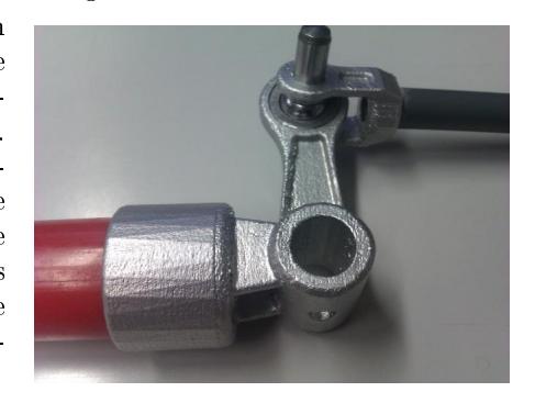
With this procedure complex items with cavities and heavily curved surfaces can be build. The design is not limited by constraints from conventional manufacturing. With this technology highly optimized structures can be manufactured [Ge1]. These are at least the joints (knee, elbow, hand) for the carbon tubes, also carrying the attachments for servos, cables and so on. As one can see in figure 3, the SLM process is ideal for producing elements like knee-joints.
4 Software and Simulation
4.1 Software
A main goal for the software team is to reuse code from 3D simulation as much as possible. The component based architecture of that code simplied this. To give a rough estimate on the success: the number of classes introduced into the framework specically for sweaty is 23. They include a specic inverse kinematic calculator, connection classes for ROS, a specic component factory and parametrization of some behaviors as well as a specic eld meta model for the dierent humanoid pitch size. Few more classes will have to be added for the game controller and some new behaviors to support. The number of Nao specic classes is 45, the number of classes shared for both is 511 (not including tools, just runtime). Of course, during the development some of these 511 classes had to be changed to make them generally usable for any humanoid robot type.
As a specic example, our walk has been reused leaving only a single class in the specic code of the robot that denes the parametrization. With a change of 13 parameters like step width or cycles per step, the same walk used for the 0.4 m Nao works for the 1.4 m Sweaty [GD1].
Reusing the structure and components of code from 3D simulation also has the advantage that the toolset can be reused including the magmaDeveloper, behaviorEditor and similar but smaller tools necessary to develop and debug bipedal robot software [Ri1].
4.2 Simulation
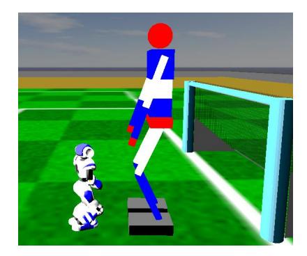
Sweaty is simulated in the simspark simulator used for 3D soccer simulation league. The simulator is based on ODE and supports gravity, rigidness and dynamics of bodies, hinge joints, maximum torque of joints, gyros, force resistance sensors, accelerometers, noise models, simulated cameras and more. Figure 4 shows Sweaty in the simspark simulation together with a simulated Nao robot.
5 Formals
- Referee: According to the rules our team will make a person with sucient knowledge of the rules available as a referee.
- Previous Achievements: Stefan Glaser and Klaus Dorer have participated with the magmaOenburg team in 3D simulation RoboCup competitions since 2009 reaching 9th, 13th, 9th, 4th and 7th place respectively in the world cup competitions. A team of the University of Appl. Sci. Oenburg has designed an electrical car during a similar project. Under the supervision of several professors of the university they were able to travel more than 1,000 miles without recharging the batteries. Lightweight design, new hub motors and new controllers were developed to achieve this result [sm1].
- Use of Software: We are especially thankful to the Nimbro team of Bonn University for their support and release of the Nimbro software. Specically we based our image processing software on their released code. The software for motion control and modeling the environment is used from our own 3D soccer simulation team magmaOenburg.
- Use of Hardware: We are also very thankful to the Nimbro team of Bonn University for the borrowing of their hardware including camera system and lenses. We could easily copy the hardware, we almost did not need any adaption of the hardware to our system.
6 Team
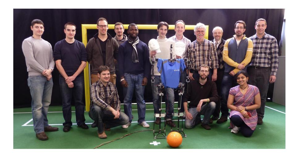
The Sweaty team: from left to right: back row: left to right: Waldemar Frei, Raphael Koger, Armin Dietsche, Michael Fehrenbach, Ibrahim Ismail, Mathias Niederhofer, Klaus Dorer, Michael Wülker, Ulrich Hochberg, Efstratios Tziallas, Rudi Kirn; front row: Igor Tropmann, Sweaty (face not decided yet), Stefan Glaser, Sneha Venkataramana
References
- Allgeuer P, Schwarz M, Pastrana J, Schueller S, Missura M and Behnke S: A ROS-based Software Framework for the NimbRo-OP Humanoid Open Platform In Proceedings of 8th Workshop on Humanoid Soccer Robots, IEEE-RAS International Conference on Humanoid Robots (Humanoids), Atlanta, October 2013
- Dorer K: Modeling Human Decision Making using Extended Behavior Networks. Baltes J et al. (Eds.): RoboCup 2009, LNAI 5949, pp. 81-91. Springer, Heidelberg, 2010
- Dorer K: Extended Behavior Networks for Behavior Selection in Dynamic and Continuous Domains. In: Visser U, et al. (Eds.) Proceedings of the ECAI workshop Agents in dynamic domains, Valencia, Spain, 2004
- Gebhardt A: Generative Fertigungsverfahren: Rapid Prototyping Rapid Tooling - Rapid Manufacturing. Hanser, 2007
- Glaser S and Dorer K: Trunk Controlled Motion Framework. In Proceedings of the 8th Workshop on Humanoid Soccer Robots, IEEE-RAS International Conference on Humanoid Robots, Atlanta, October 2013
- Hochberg U, Dietsche A and Dorer K: Evaporative Cooling of Actuators for Humanoid Robots. In Proceedings of the 8th Workshop on Humanoid Soccer Robots, IEEE-RAS International Conference on Humanoid Robots, Atlanta, October 2013
- Kurth M: Steuerung eines simulierten Roboters mit Hilfe von Motion Capturing Files. Bachelor thesis, Hochschule Oenburg, 2011
- Ritter B: Steuerung simulierter Roboter mit Kinect. Bachelor thesis, Hochschule Oenburg, 2012
- Fehrenbach M: Entwicklung eines Wärmemodells zur Berechnung der Wicklungstemperatur eines Servomotors mit Verdunstungskühlung. Bachelor thesis, Hochschule Oenburg, 2014
- Schultz G, Mombaur K: Modeling and Optimal Comtrol of Human-Like Running. IEEE/ASME Transactions on Mechatronics, Vol. 15, No. 5 (2010) pp. 782-792.
- www.maxonmotor.ch/maxon/view/product/motor/dcmotor/remax/remax17/214897 8th Jan. 2013.
- www.smartplanet.com/blog/transportation/ev-travels-1000-miles-on-a-singlecharge/779 8th Jan. 2013.
- ITI Gesellschaft für ingenieurtechnische Informationsverarbeitung mbH, Multidisziplinierte Simulation und Modellierung, 2012 [Online]. Available: http://www.iti.de/.
- SUNDIALS (SUite of Nonlinear and DIerential/ALgebraic equation Solvers), 2012. [Online]. Available: https://computation.llnl.gov/casc/sundials/main.html.
- www.robotis.com
- www.opencv.org
- www.volz-servos.com
- www.tekscan.com
- www.st.com
- www.linear.com/designtools/software/
- www.cadsoftusa.com