Tsinghua Hephaestus 2015 AdultSize Team Description
Mingguo Zhao, Qingqiu Huang, Yifan Hou, Fei Tan, Yangyang Li
Tsinghua University, Beijing, China
Abstract This document describes both hardware and software specifications and practical functions of the humanoid robot THU-Strider, developed by team Tsinghua Hephaestus as a platform for research in bipedal locomotion, robot self-localization and multi-robot cooperation. The robot will also be used to participate in the Humanoid League(AdultSize) of RoboCup 2015 China.
1 Introduction
The Tsinghua Hephaestus is a RoboCup Humanoid League team running at Dept. of Automation, Tsinghua University, China, since July 2006. Before that, we had three years participation experience in RoboCup Four Legged League and got the fifth place in the Technical Challenges of RoboCup2006 Bremen. Our current research interest is focused on bipedal locomotion[1][2][3][4], robot self-localization[5][6] and multi-robot cooperation in dynamic environment[7]. The team has got 3rd place five times and 2rd place twice (2008 and 2012).
THU-Strider is an AdultSize humanoid soccer robot developed as a platform for Tsinghua Hephaestus RoboCup team in RoboCup 2011. The main goal is to develop a light weight and fast walking soccer robot. A passive dynamic walking based powered walking-Virtual Slope Walking is been developed for gait generation and some mechanical refinements are ongoing. Also a variety of technological advancements on computer vision is put into use. This document will give a general overview of the robot.
This year, we implement legged locomotion for our robot in both passive and active way and try to make the robot to walk imitating a person. What's more, a new method that can detect a striped ball has been developed. We also try to make the robot walk like a person by employing path planning. Now we have been getting prepared for Robocup 2015.
2 The Robot Design
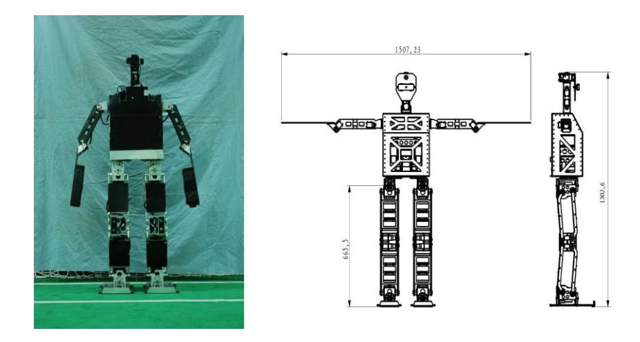
Fig 1-1) shows our THU-Strider robot in practice. The robot has a height of 1320 mm, and weights 18.10 Kg, including batteries. The detailed dimensions are shown in Fig. 1-2). The robot has 18 DOFs: 5 in each leg, 3 in each arm, 2 in the head.
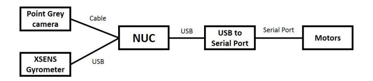
For THU-Strider, 10 Vstone V3310 servo motors are used as actuators for legs and 8 Robotis EX106+ for arms. We use an Intel NUC DC32171YE as the Main Controller of the robot, with two USB ports(one for the motion-controller, another for the gyro) and a cable for the camera. Specifically, an Mti-28A83G25 Gyro is mounted on top of the robot head, while a Pointgrey Blackfly camera located in the robot head is employed as our visual sensor. Buttons and LEDs, located on the back, are set to control and indicate the robot state. The motors of upper body are connected in series on a RS-485 bus and lower body (leg) motors are connected in series on a LVTTL bus. The details of the control system are shown in Fig. 2.
3 Software Architecture
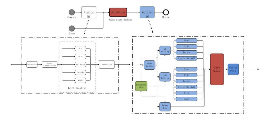
The software architecture is developed on Robot-Operating-System(ROS) and the distribution used is ROS Hydro. The whole software system consists of three main modules: Cognition, Behavior and Motion. Each module runs several different nodes in parallel to realize a specific function. Modules are arranged so that they are independent from each other. Both Cognition and Motion interchange data with Behavior through ROS messages or services. Cognition is responsible for information gathering from both camera and Gyro, self-localization and perception. Motion is responsible for gait planning and motor controlling, while Behavior acts as the brain of the robot, analyzing the data from Cognition and sending orders to Motion. Module configurations and data flows are shown in Fig. 3.
Image Grabber grabs images from the vision sensor and generates related information of the image and the pose of the camera.
Image Processor processes the incoming images grabbed by Image Grabber, and yields information needed for Localization and Behavior Control.
Localization&Perception: implements the Particle Filter localization algorithm, manages position information of robots and the ball, so as to be used by Behavior Control.
Behavior controls the game process and makes behavior decisions.
Motion Control manages all the actuators of the robot, and controls locomotion or any other actions of the robot according to the requests from Behavior.
Sensor Control manages other sensors, and interacts with the Sub-Controller.
4 Vision
A Point Grey camera with a Computar M0814-MP Lens is employed as our visual sensor. The Vision module has two tasks: object recognition and relative position estimation. We first map the RGB pixels to 8 color space simultaneously. Then, we resize the original image into a smaller one and use it for the detection of our objects, thus saving computational resources. This procedure takes full advantage of the tools the newly applied ROS middle-ware provides us with.
4.1 Vision Sensor
A Point Grey camera (BFLY-PGE-13E4C-CS) with a Computar M0814-MP Lens is used to provide the visual input of our robot. This combination yields a eld of view of about 70*°* (horizontal) × 60*°* (vertical). The robot has to rotate its head to widen this field. The connection to the main controller via the cable provides real-time image series of a resolution of 800 × 600 of 30 fps, but as explained earlier, the resized images used for object detection have a resolution of 480 × 360.
4.2 Color Segmentation
After images are captured, firstly we use the manual calibration, and then use machine learning method to map the RGB pixels to 8 color space simultaneously. In this way we can minimize the storage cost, using a monochromatic image to greatly reduce the storage space required and avoid the waste of bandwidth for the transmission of the image to the object detecting modules.
4.3 Feature Extraction
Objects are distinguished by colors and shapes. As the features, clusters of different colors were extracted along the scan line from top to bottom or left to right. And the process would end if no more special colors appear. The special color found calls further object recognition in related areas. For instance, consecutive orange pixels (maybe white this year) call the process of ball detector. Single special colored point would not be considered as a target object, in case there is some expected error spot in the image especially under walking or other dynamic situations.
4.4 Object Recognition
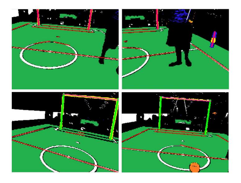
Features, characteristic series of colors or a pattern of colors, are used for object recognition, e.g., a sequence of some orange pixels (maybe white this year) is an indication of a ball. Fig. 4 shows the recognized ball, goal and obstacles in the image.
Ball detector After Color Segmentation, Breadth First Search (BFS) is used in order to obtain all the contours segmented by the color of ball as candidate regions with noise avoiding. Then for each candidate region, the convex set of the region is calculated and three points are sampled randomly on its edge. At last, a circle is fitted with these points and the fitting error is evaluated with regard to occlusion and shadows. If the error is less than a certain threshold, this region is accepted as a ball.
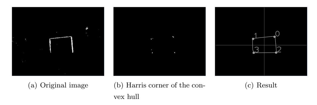
Goal detector Goal is a reasonably large rectangle area with yellow pixels (maybe white this year), whose main character is four corner points. The goal detector first searches all the connected domains in yellow and find the contours of these domains. Those contours in relatively small size will be considered as noise and ignored. Afterwards, the convex hull of these contours is calculated, and then, corner points of the hull are calculated using Harris algorithm[8]. The area where corner points concentrate in is regarded as the corner of the goal. The result is shown in fig. 5.
Field and Obstacle detector After the field is detected using its characteristic green color and already known shape, we look for black or dark colored objects that interrupt the field pattern and categorize them accordingly, calculating their width and distance.
Field Line detector A square frame with a specific width is the area in which we detect whether white spots exist. Since the penalty spot is isolated, if there is no white spot in a square frame, while its central point is white, this central point will be regarded as one pixel of the penalty spot. The result of penalty spot detector and the information of the boundary line of the field are used at the same time to detect the field lines and the method implemented is Hough transformation. 4.
5 Localization
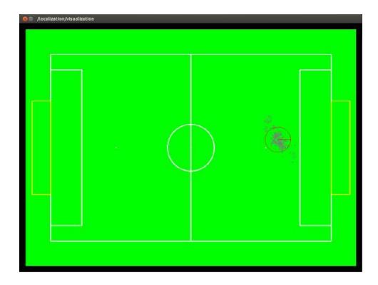
Apparently, in the game, the position of the robot is indispensable in making a proper decision of behaviour control. We implement an algorithm of localization based on Particle Filter (Monte Carlo Localization), using the information through our visual, gyro sensors as well as odometry data from the movement commands given.
One of the key ideas of the algorithm is Bayes Filter. Recursively applying the Bayes formula, P(B|A) = P (B∩A) / P (A) , we can update the belief of each state, i.e. the probability of the position of the robot, in real time. Therefore, we are able to estimate the position by the method of maximum likelihood.
However, in practice, it's impossible to calculate the posterior by an infinite number of parameters, so the alternative idea is to perform an approximation, which is implemented by the particle filter. It uses a finite number of particles to represent concrete instantiations of states in real time, with a positive weight denoting the possibility of the position. In that way, we can approximate the belief of each state recursively by constructing the particle set X^t from the set X^t−1.
Hence, we can derive the position of the robot effectively from the mean pose of the particles.
6 Behavior Control
The data provided by the sensors and localization modules is used to plan a more complex behavior series. And the module of Behavior Control takes charge of this task. The main task is separated into subtasks until they can be described as a set of basic behaviors which can be executed by the robot. All these are done by a hierarchical state machine described in XABSL (Extensible Agent Behavior Specification Language). The basic motion actions are transferred to and interpreted by the motion module, while other basic actions are processed in further modules.
It can output the following variables: 1) A motion request of basic behaviors to inform the motion module of the robot's next action. 2) A head motion request of head mode to inform the motion module of the robot's next head action. 3) 3 LED's state. An XABSL behavior specification is comprised by a set of behavior modules called options and a set of different simple actions called basic behaviors. Each option consists of various numbers of states or subordinate options. Each state has two parts of information, decisions and actions. Decisions describe the conditions whether to jump out or stay in the current state according to the input variable, while the actions consist of the outputs such as the basic behaviors, LEDs etc.
7 Gait Planning
For low level motion control, we implemented legged locomotion for our robot in both passive and active way. A state-machine for gait control is designed for handling switching of different gaits.
7.1 Passive Gait
The implementation of passive forward walking is applying Virtual Slope Walking in the sagittal plane with the Lateral Swing Movement for lateral stability[1]. We have achieved a maximum forward walking speed of 0.6m/s on THU-strider. The side-walking and turning are realized by carefully designing the key frames. The entire gait is generated by connecting the key frames with smooth sinusoids.
7.2 Active Gait
A ZMP-based online motion generation scheme is adopted for kicking gait and small steps motion design&control. Kinematic teaching is used to enable fast, flexible motion generation[9]. Human motion captured from Kinect is modified to ensure the static balance during the robot playback. We further enable the algorithm to run online, with dynamic balance using a hierarchal approach: Firstly use an IP model for pattern generation, then use a full-body model for whole-body motion control.
Gait planning is mainly done by the ROS program running on the NUC. When we get basic motion requests from a higher in hierarchy module, motion is translated into instructions for each joint actuator. Instructions keep being sent out to every motor at 20Hz so as to make the robot move as expected.
8 Conclusion
Our AdultSize robot THU-Strider is a completely autonomous humanoid robot, with 1 camera, 1 gyro and 18 actuators integrated on body, controlled by a NUC. In this paper we present the specifications and functions of the THU-Strider, as well as some related works on vision, localization, gait planning and control.
Tsinghua Hephaestus commits to participate in RoboCup 2015 in Hefei, China and to provide a referee knowledgable of the rules of the Humanoid League.
References
- M. Zhao, J. Zhang, H. Dong, Y. Liu, L. Li and X. Su, Humanoid Robot Gait Generation Based on Limit Cycle Stability, In the proceedings of the RoboCup Symposium 2008., LNAI 5399, pp. 403-413, 2009.
- M. Zhao, H. Dong and N. Zhang, The instantaneous leg extension model of Virtual Slope Walking, IEEE/RSJ International Conference on Intelligent Robots and Systems, pp. 3220- 3225, Oct. 2009.
- H. Dong, M. Mingguo Zhao, J. Zhang andN. Zhang, Hardware design and gait generation of humanoid soccer robot Stepper-3D, Robotics and Autonomous Systems, vol. 57, no. 8, pp. 828-838, 2009.
- H. Dong, M. Zhao and N. Zhang, High-speed and energy-efficient biped locomotion based on Virtual Slope Walking, Autonomous Robots, vol. 30, no. 2, pp. 199-216, Jan. 2011.
- Y. Cai, M. Zhao, Z. Shi and W. Xu, "An Experimental Comparison of Localiza tion Methods in Robocup Four Legged League", Robot, 2007, Vol. 29, No. 2, pp167-170.
- Z. Liu, Z. Shi, M. Zhao and W. Xu, Mobile robots global localization using adaptive dynamic clustered particle filters, IEEE/RSJ International Conference on Intelligent Robots and Systems, pp. 1059-1064, 2007.
- Z. Liu, M. Zhao, Z. Shi and W. Xu, Multi-robot Cooperative Localization through Collaborative Visual Object Tracking, In the proceedings of RoboCup 2007 Symposium, LNAI 5001, pp. 41-52, May. 2008.
- C. Harris and M. Stephens, A Combined Corner and Edge Detector, Proc. of Fourth Alvey Vision Conference, pp. 147-151, 1988.
- Y. Hou and M. Zhao "Follow My Step: A Framework for Biped Robots to Imitate Human Walking," 2014 IEEE International Conference on Robotics and Biomimetics,pp. 2471-2476, 2014.