IRC Team Description Paper 2018
Mortaza Abbaszadeh, Arash Ranjbaran, Ghafour Alipour, Vahid Alizadeh Marandi, Farid Mahdavi Ilkhechi
Department of Computer Science, Ilkhchi Branch, Islamic Azad University, Ilkhchi, Iran
Abstract This paper describes the Artin Humanoid Adult-size Robot trying to qualify for RoboCup2018 competition. The main characters of our Robot including mechanical design, electrical design, vision part and software design are described and some new improvements that have been made or are planned to be implemented for RoboCup 2018.
1. Introduction
To stimulate the development of multifunction humanoid robot, there are two well-known robot competitions held annually in the world, namely FIRA Robo-World Cup[1] and RoboCup[2]. Both of them contain several challenge events to encourage research in practical such as stable walk pattern generation[3-7], real-time image processing, intelligent decision making system, and fully autonomous ability[8].
Actually main aims of this type competitions and this kind of activities to increase the scope of artificial intelligence from various aspects. In this way, our team obtained 3rd place in the first appearance at RoboCup 2016 and again obtained 3rd place at RoboCup 2017. However, our team after the RoboCup all their efforts to improve different aspects of IRC robot.

Hardware and electronics
The characteristics of our robot hardware and software have been discussed in two separate parts in this section.
1.1. Mechanical structure
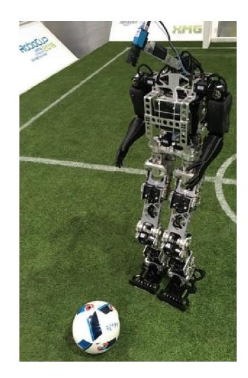
Artin that shown in figure 1. The most parts of mechanical structure in lower limb of robot is building of aluminum alloy by CNC machining. Also the upper body of Artin printed by 3D printer with PLA Alloys. The actuators used in Artin is MX-106t servo motors series that manufactured by Robotis company. Number of motors used for each kinematic chain of kneeshin-ankle-foot is 17, which enables 6 DOF in each leg. Also in the Artin's hands 3 motors for each hand used. Finally, there are 2 motors for robot head for pan and tilt movement of camera. In total DOF of Artin is 20. The Artin's configuration details have been explained in table 1.
Table 1. Hardware details of Artin
| Robot System | Artin |
|---|---|
| Weight | 25 kg |
| Height | 133 cm |
| DOF | 20 |
| Actuators | MX-106 |
| Vision System | Imaging Source® DFK 23G618 |
| Processing unit | Intel® Core™ i5 4250U processor, QBOX mini pc 2000 |
| OS | Windows 10 |
| Battery | Li-Po 11.1 V 8000 mA |
1.1. Electronics Structure
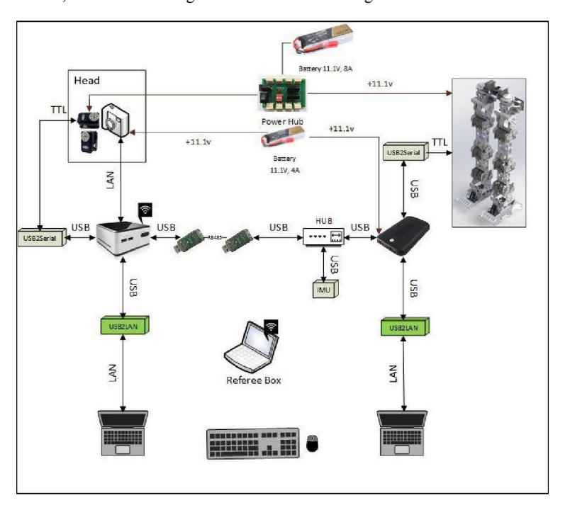
We used different kind of electronic modules that detailed below for controlling different parts of our robot that in this part we describe all of them. Also, the electrical design of our robot shown in figure 2.
1.2. Mini PC: Intel® NUC
We used this module as central processing unit which its operation system is windows 7.
- Intel® Core™ i5 4250U processor
- DDR3 SO-DIMM Socket
- 1x HDMI,1x Mini HDMI, 4x USB3.0
- 1x Phone Jack for both Line-Out & Mic-In
1.3. QBOX mini pc 2000
We used this module to control all of servo motors to help robot walking process which its operation system is windows 7.
- Intel® Atom™ Processor N2600
- Intel® NM10 Express Chipset
- DDR3 SO-DIMM Socket
- 1x HDMI, 3x USB2.0
- 1x Phone Jack for both Line-Out & Mic-In
- 1x mSATA
- 1x mPCIe Socket for Wi-Fi Module
1.4. GY80
This module contains compass (HMC5883L), accelerometer (ADXL345) and gyroscope (L3G4200D) sensors that are used for the purpose of this information is to maintain balance and orientation.
Description:
- ✓ Nine-axis module (Three-axis gyroscope + triaxial accelerometer + 3-axis magnetic field + pressure)
- ✓ Immersion Gold PCB process
- ✓ The use of chip: L3G4200D + the ADXL345 + HMC5883L + BMP085
- ✓ Power supply :3-5v
- ✓ Means of communication: IIC communication protocol (fully compatible with the system 3-5v)
- ✓ Module Size: 25.8mm * 16.8mm mounting hole 3mm
- ✓ Standard 2.54mm pin interface, convenient bread plate experiments connection
1.5. Machine vision
(Machine vision section)
1.5.1. Imaging Source DFK 23G618 camera
In our robot image processing and machine vision step we used an industrial camera that named "DFK 23U618" in new Robot, that made by "Imaging source" company. The configuration of this camera presented as follow.
2. Software Description
In this part we describe our humanoid robot software's detail and characteristics in separate parts as follow.
2.1. Robot Motions and Controlling
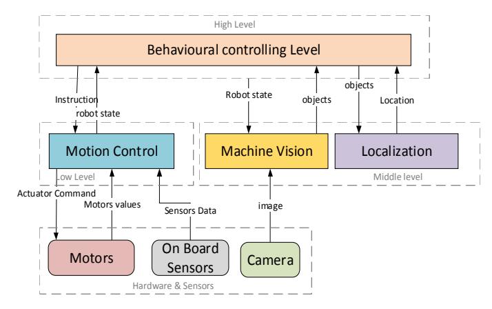
As we know one of the serious challenges in adult size humanoid robots is walking in the field. For this issue we have to use some different kinds of sensors. According to the previous section, we used QBOX mini pc for controlling our robot to walking. But, in the previous version[9] of IRC Robot, had been used CM9 controller for this task. In this way, we used GY80 sensor data. This data is used for balancing our robot in the different fields. It's obvious that when one humanoid robot is walking in the field there are a lot of noise in our balance sensor. Therefore, we implemented Kalman Filter for improving this sensor data.
After collecting filtered GY80 data and according to our motors type, we implemented one dynamic walking algorithm. In fact, our walking trajectory is combination of our proposed method and NAO based robots simulation. In this way, we use this simulation results for walking our robot. Also, in our robot there are some static motions which combined with dynamic behaviors through implementation of inverse Kinematic. For instance, kicking the ball has some static motions, which combined with dynamic states by assessing the data from GY80 sensor.
2.2. Image Processing and Behavior Controlling
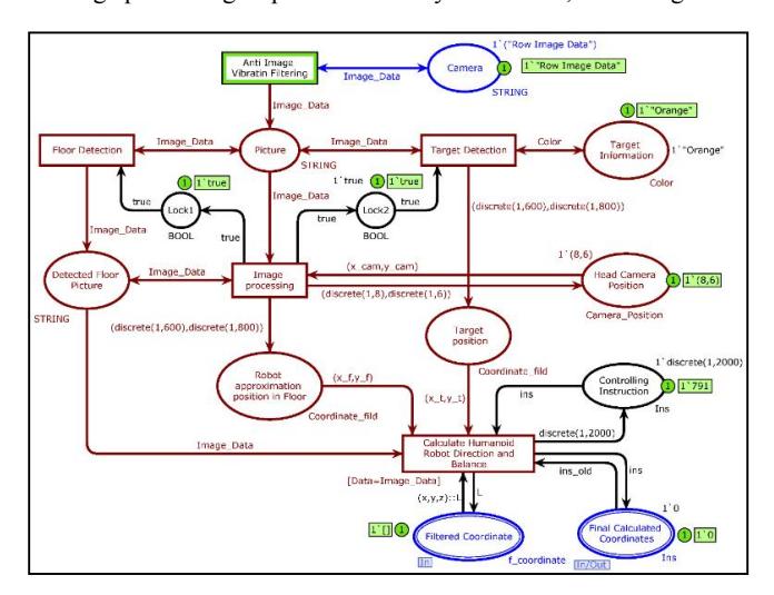
For image processing we used related mentioned camera. This Camera is connected to the system via Ethernet cable. We used C#.Net programming language for our image processing and controlling steps. Our used OS is windows 7. In the figure 4 our robot image processing steps is modeled by CPN-Tolls, modelling software.
2.2.1. Ball and Goal Detection
For ball and goal detection in our robot, we use object detection in image. For this operation we implemented one software in C# language in which we determine and select color range of each objects. After this step, all obtained spots have been investigated from shape aspect. In this way, we used several methods to detect main objects on the field. In addition, we are able to recognize and detect needed objects from each frame of pictures. Also for ball detecting movement we track it by center location of ball through detecting the ball circular edges. After that if the ball's center position will change, our robot will track it by head movement in PT directions.
2.2.2. Localization
We had rewritten some localization algorithms by our presented algorithm in which there are few steps. In first step our robot tries to find field center lines. In second step, it calculates direction of the first line that there is in front, for knowing detection robot side. In third step our robot tries to find correct goal for attacking. In this way, it avoided from any obstacles that there are on the path.
3. Conclusion
Humanoid Robots are one of the most complicated robots in building and controlling steps. Humanoid Robots competition is one great opportunity for progressing in robotic science. Our team has some different experiences in kid and Adult-size Humanoid robots. After the last success on RoboCup 2017, we tried to improve our Adult-size Robot from software and hardware aspect. In this way, we did several work, that have been explained in this paper.
Our IRC robot is one autonomous adult-size humanoid robot that is completely built manually.
There are no sources in the current document. Finally, we are going to improve our robot behaviors step by step, also we aim to use evolutionary algorithms on our robot as much as it is possible.
References
- FIRA RoboWorld Cup. Available from: http://www.fira.net/.
- Robocup Available from: https://www.robocuphumanoid.org/.
- Li, T.-H.S., et al., Walking motion generation, synthesis, and control for biped robot by using PGRL, LPI, and fuzzy logic. IEEE Transactions on Systems, Man, and Cybernetics, Part B (Cybernetics), 2011. 41(3): p. 736-748.
- Kuo, P.-H., et al. Development of humanoid robot simulator for gait learning by using particle swarm optimization. in Systems, Man, and Cybernetics (SMC), 2013 IEEE International Conference on. 2013. IEEE.
- Li, T.-H.S., et al., A Biped Gait Learning Algorithm for Humanoid Robots Based on Environmental Impact Assessed Artificial Bee Colony. IEEE Access, 2015. 3: p. 13-26.
- Morimoto, J., et al., A biologically inspired biped locomotion strategy for humanoid robots: Modulation of sinusoidal patterns by a coupled oscillator model. IEEE Transactions on Robotics, 2008. 24(1): p. 185-191.
- Liu, C., D. Wang, and Q. Chen, Central pattern generator inspired control for adaptive walking of biped robots. IEEE Transactions on Systems, Man, and Cybernetics: Systems, 2013. 43(5): p. 1206-1215.
- Ho, Y.-F., et al., Control Strategy Design for Throw-in Challenge in a Humanoid Robot Soccer Game, in Robot Intelligence Technology and Applications 4. 2017, Springer. p. 101-112.
- IRC Adult-size Humanoid Robot Soccer Team Description Paper 2017, in RoboCup2017, S. Saeedvand, et al., Editors. 2017: Nagoya, Japan.