Humanoid Robots: Abarenbou and DaoDan
Jacky Baltes, Sancho McCann, John Anderson
Autonomous Agent Lab University of Manitoba Winnipeg, Manitoba Canada, R3T 2N2
http://www.cs.umanitoba.ca/~jacky
Abstract This paper describes our latest humanoid robots ABARENBOU and DAODAN. ABARENBOU is a modification of the commercially available Kondo KHR-1 humanoid robotic kit. The research goal of ABARENBOU is the development of an affordable
This kit provides a mechanically sound and affordable platform, but does not provide facilities for on-board computer vision and other sensors for active balancing. Thus, it is not suitable as a research platform for humanoid robotics. To overcome these limitations, we added a pan and tilt camera mount, a small camera. Processing power is provided by a Sony Clie NR70V PDA which is responsible for computer vision and higher level reasoning. The PDA communicates with the robot kit via a serial line. We developed software to create, store, and play back motion sequences on the Kondo KHR-1.
1 Introduction
Humanoid robots have always inspired the imagination of robotics researchers as well as the general public. Up until 2000, the design and construction of a humanoid robot was very expensive and limited to a few well funded research labs and companies (e.g., Honda Asimov, Fujitsu HOAP). Starting in about 2001 advances in material sciences, motors, batteries, sensors, and the continuing increase in processing power available to embedded systems developers has led to a new generation of affordable small humanoid robots (some examples include: Pino [7], Manus I [8], Tao-Pie-Pie [2], Roboerectus [9], and Hansa Ram [5]).
These robots cost in the range from $1000.00 to $20,000 USD. Many hobbyists have build their own humanoid robots, especially in Asia.
The creation of these humanoid robots also coincided with an increased interest in several high profile research oriented international robotics competitions (e.g., RoboCup [3] and FIRA [1]). The researchers chose robotic soccer as a challenge problem for the academic fields of artificial intelligence and robotics. Robotic soccer requires a large amount of intelligence at various levels of abstraction (e.g., offensive vs defensive strategy, role assignment, path planning, localization, computer vision, motion control). Robotic soccer is a dynamic real-time
environment with multiple agents and active opponents that try to prevent the robot from achieving its goal. These competitions allowed researchers to compare their results to others in a real-world environment. It also meant that robustness, flexibility, and adaptability became more important since these robots had to perform for extended periods of time in variable conditions. This is in contrast to researchers that could previously fine tune their system to the specific conditions in their laboratory. The inaugural humanoid robotics competition at RoboCup and at FIRA were held in 2002.
Furthermore, in 2002 hobbyists formed several popular robotics events which had less of a research emphasis. The most popular example are the televised Robot Wars (Battle Bots) events where remote controlled wheeled robots with weapons try to destroy each other. The huge interest in humanoid robotics in Asia has led to the creation of humanoid robot fighting competitions in Japan (Japan One) and Korea (K-One). Several of these humanoid robots are now commercially available at a competitive price. Even though the robustness and cost make these remote controlled fighting robots attractive for humanoid robotics researchers, the robots are not immediately suitable as autonomous robot research platforms.
The main disadvantages are: (a) these fighting robots do not have sufficient processing power for on-board vision, and (b) they have few if any sensors (e.g., accelerometers, gyroscopes, force sensors) to support dynamic balancing and feedback control of the walking gait.
This paper describes our work in converting the Kondo KHR-1 humanoid robot kit from a remote controlled fighting robot into a fully autonomous soccer playing robot Abarenbou. To keep the cost down, Abarenbou uses a commonly available personal digital assistant (PDA) with a built in camera as processing platform for vision and higher level reasoning. We used the Sony Clie NR70V PDA as the brain of our robot.
The following section describes the hardware of the Kondo KHR-1 robot and our modifications to the hardware. Section 4 describes the methodology we used for developing new motions (e.g., walk, turn, and kick). The vision processing part of our system is described in section 5. Section 6 describes our pragmatic Al method for localizing the robot in the playing field and mapping the environment around the robot. The agent architecture is described in Section 7. The paper concludes with section 8, which also gives directions for future work.
2 Team Members
For the last three years, the Keystone Rescue is an important and integral part of our research into articial intelligence, computer vision and machine learning. Various students and staff have contributed to the 2006 Keystone Rescue team and a comprehensive list would be too long. The following table lists the core team members of the Keystone Rescue 2006.
Core team members of the Keystone Rescue 2006
| Jacky Baltes | team leader, hardware John Anderson robot coordination | |||
|---|---|---|---|---|
| Sara McGrath | vision | Terry Liu | map generation | |
| Sancho McCann victim identification | Shane Yankee | path planning |
3 Hardware Description
3.1 Abarenbou
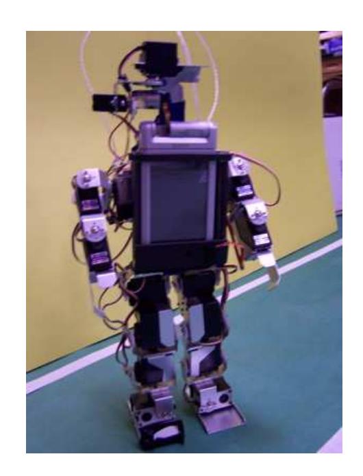
The Kondo KHR-1 robot is a humanoid robotics kit with 17 degrees of freedom (DOF) controlled by servo motors. These include two in each ankle for frontal and lateral movement of the foot, one in each knee, two at each hip for frontal and lateral movement of the leg, three in each arm, and one to pan the head. The KRS-784ICS servo provides 8.7kg/cm at 6.0 V of torque and a maximum speed of 0.17sec/60◦ . These servos are powerful given their cost and were the main reason that we decided on this robot kit.
The servos are controlled by two simple PIC based micro-controller board. Each board can control a maximum of 12 different servos; this means that in theory the Kondo KHR-1 kit can control up to 24 different servos. However, in practice the number of servos is limited by the maximum current that can be driven by the controller boards. To reduce the maximum current for the two boards, the 17 servos of the KHR-1 are distributed equally across the two boards. The first controller board is responsible for the legs, whereas the upper torso, arms, and head are controlled by the second controller board.
The two embedded systems are controlled via a shared serial line. The controller boards accept commands at 115200 baud. Commands include setting the position (i.e., set point for all 17 servos), writing a motion (i.e., a sequence of positions), as well as reading back positions and motions. The firmware of the controller boards is limited to 31 motions.
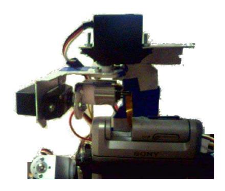
Several additions were made to the standard kit. A pan and tilt camera unit was constructed using two servo motors and the camera from a Sony Clie NR70V PDA 1. First, we removed the camera from the Sony Clie NR70V casing. The camera is connected to the main board via a fragile short ribbon cable. This means that the camera only has a small range of motion. Therefore, a pan and tilt unit was constructed out of two micro RC servos in such a way that the link joint as close as possible to the original position of the camera. The pan and tilt assembly allows the camera to tilt by +/- 45 degrees and to pan by +/- 70 degrees. The Clie itself was mounted in a bracket attached to the front of the robot.
The PDA uses a 66 MHz Dragonball CPU for processing and captures images with a 320x240 resolution. While the PDA does not have as much processing power as other alternatives, it does have a serial port for communication with Abarenbou's control boards. A MAX232 based level changer is used to convert the voltage from TTL level (PDA) to RS232 level (Abarenbou controller board). After generating the correct voltage, we were able to send data to the robot, but were unable to read data from the robot successfully. Upon further investigation, we discovered that the control circuitry on the robot did not generate 12V.
Instead the client software was expected to drive the DTR pin low, and this pin was connected via a pull down resistor to the transmit pin on the robot. We generated a 12V signal using the Maxim MAX232 level changer IC in a similar manner. After this modification, we were able to send and receive data from the robot reliably.
After these modifications, Abarenbou has a height of 41cm, each foot has a surface contact area of 41.85cm², and the center of gravity is at a height of 18.5cm.
3.2 DaoDan
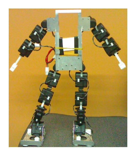
DaoDan is our latest and most sophisticated humanoid robot. It has 17 degrees of freedom. DaoDan uses the A1001 AI motors from the Korean company Megarobotics. These motors are provide about 10 kg/cm torque but have several features that make them attractive for complex robots such as humanoids.
Firstly, the motors use a TTL level serial protocol which means that they can be daisy chained. This greatly simplifies the cabling of the robot. Secondly, the AI motors provide position and torque feedback. This makes it easier to develop stable walking gaits. We are also currently investigating methods where this feedback is used to actively control the angle of the upper torso to reduce the torque on the ankle joints. The torque on the ankle joints is a limiting factor in the development of walking gaits for humanoid robots, since all but the most expensive RC servos do not have enough torque to support a robot in the single support phase. In spite of these advantages, the A1001 AI motors are reasonably priced at approximately $50.00 CAN. This is in stark contrast to the $150 CAN or more that other teams spend on the robotis servos or high quality digital servos from Hitec and Futaba.
DaoDan uses Li-Polymer batteries because of their good power density and maximum current.
DaoDan is being controlled by a Palm Zire 72 PDA, which has a powerful arm based processor running at 312Mhz Intel PXA270 processor. It includes 32 MB of RAM (24 MB usable) which is sufficient for most robotics applications. The PDA has a built-in bluetooth connection and a large 320x200 display which are useful in debugging.
4 Motion Development
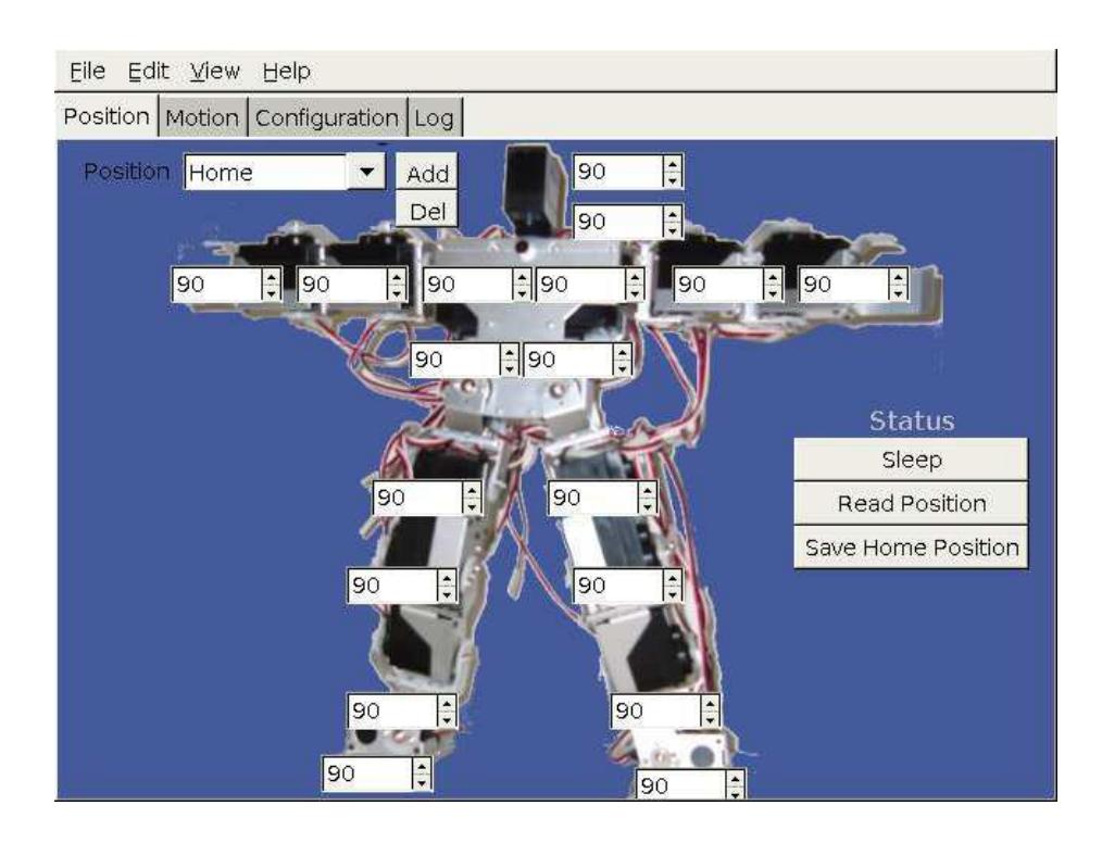
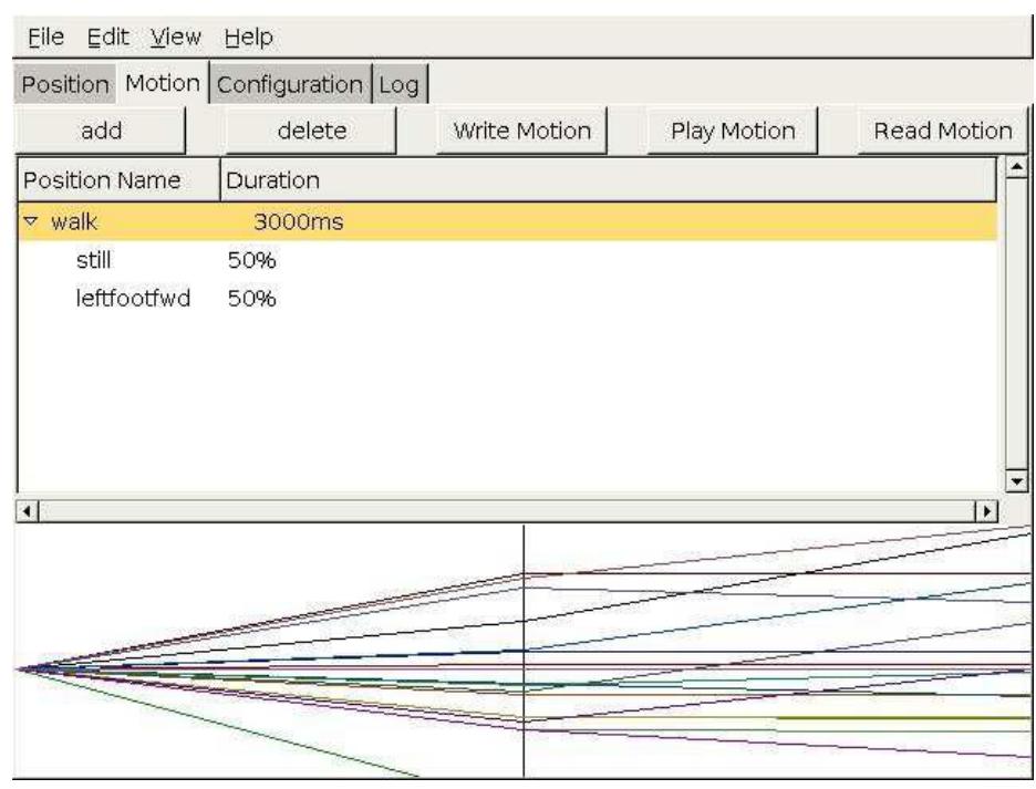
Figure 4 shows the interface of the motion control software that we developed to control Abarenbou and DaoDan. The interface allows one to move the robot into a specific position and save this position. The interface also allows one to set the trim (i.e., offset) for all joints as well as the home position.
A separate window tab is used to combine positions into motions. Each motion has a cycle time associated with it and each part of a motion has a arrival time associated with it. Thus, the interface allows the user to easily adjust the speed of a whole motion or individual parts of the motion. The trajectory of all joints is shown in the bottom window.
Eight movements were programmed onto the robot: start walking, take step with right foot, take step with left foot, stop from left walk, stop from right walk, sideways step left, sideways step right, and kick with right foot.
These movements are then available to be played back as required by any of our programs running on the PDA.
5 Vision Processing
Abarenbou uses a CMOS camera as the main sensor. The camera is used to approach objects in the field of view of the robot as well as localization and mapping.
To be robust enough to deal with the complex environment of robotic soccer, the vision processing makes little use of colours, but uses a very fast approximate region segmentation algorithm. First, the algorithms scans the image and extracts scan line segments (i.e., segments of similar colour) of approximately the right size. This step is similar to standard region segmentation algorithms.
However, we noticed that implementing a full union-find algorithm was too slow since it took about 2 secs. per image. Since most objects of interest in the environment are relatively small, we use a flood fill pixel merge algorithm, to find the associated region for a scanline. Note that the flood fill algorithms keeps track of which pixels have previously been visited and thus will visit each pixel at most once. The returned region is then checked for size (i.e., number of connected pixels), size of the bounding box, aspect ratio, and compactness. Only in the final step does the algorithm test whether the average colour of the region matches the object colour. If any of these tests fail, the object is rejected. Using only average colours of regions results in robust recognition of the ball and the goals and takes on average approximately 200ms.
An approximation of the relative position of objects is possible by determining the pan and tilt angles, and then calculating the distance to the centre of the image. It is assumed that these objects are on the ground plane. The relative position of an object at the centre of the image will have the closest approximation, so the camera is centered on important objects such as the ball before a decision is made as to what action to take next.
Goals are also detected as objects. Each goal is a distinct colour according to RoboCup rules. If both goal colours are found in one image, the regions of each goal colour are merged with other regions of the same goal colour. The goal colour that is present in the largest merged region is considered to be the goal currently being viewed.
To help the feature based localization method described in the following section, we use a complex camera calibration based on the Tsai camera calibration algorithm [6]. This calibration is only done once for each robot. Given this calibration information, we are able to map points in the image accurately to their real world coordinates. This is essential since it allows us to determine the distance and orientation of the ball to a feature point (ball, goal post, line)
Before localization can occur, features must be extracted from the image. The relevant features for localization on the soccer field are lines, goals, and the centre circle. We use the lines and the goals to achieve localization.
Every 5th column, the system scans from the bottom of the image towards the top. If there is a transition from a green pixel to a white pixel, the pixel p is remembered in a list. The scan continues upward, so there may be more than one transition pixel in a column.
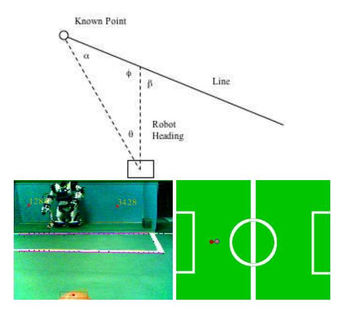
Next, lines are found by running a gradient guided Hough transform [4]. For each point pi , a set of adjacent points is determined. Triplets are formed from these by including one point to the left of the point pi , and one point to the right of pi . There are several triplets that can be formed this way out of the neighborhood of adjacent points. Each triplet votes for an unbounded line in the image. This vote is fuzzified by voting for a small range of slopes through the point pi .
The peaks in the Hough accumulator space determine the equations of possible lines. For each peak in the accumulator space, we search along the pixels determined by the line equation to find start and end points of the lines. This results in a set of line segments.
The line segments are ordered based on their size. The longest line segment is assumed to represent the edge of the playing field. Given the distance and gradient of the line segment, the position and direction of the robot can be computed.
6 Localization and Mapping
Knowing the position of the ball is important. Its relative position from the robot is easily determined from an image. However, without knowing the world position of the ball, the robot would often kick the ball out of bound or even into its own goal. Actions can not be taken toward kicking the ball until its world position is known.
Absolute localization of the robot will give absolute localization of the ball. Absolute localization can be done as long as a point is viewed with a known world coordinate, and knowing the robot's world bearing from it. One instance of this is when a goal post is seen. Once this is accomplished, dead reckoning can be used with some accuracy for a short time afterward.
7 Agent Architecture
This section will give a brief introduction to the behaviour tree based agent architecture used in Abarenbou. The discussion will focus on the state transitions. More complex features of the agent architecture (e.g., behaviour trees and state references) are outside of the scope of this paper.
Designing an architecture that is flexible, versatile, and intuitive enough for an intelligent mobile robot is a difficult problem. This is especially true in the case of autonomous robots with limited processing capabilities.
Abarenbou uses a behaviour tree to balance the need for deliberate planning and reactive behaviours. The behaviours themselves are implemented as finite state machines. As the complexity of the task increases, the implementation of the state machine becomes more error prone.
We therefore developed a meta language to describe the behaviors in XML. The specification of the behaviors includes preconditions (enter functions) and post conditions (exit functions) of the behaviours. An slightly simplified example of a simple behaviour that scans for a target with increasing sweeps is shown in Table 1.
<State id="Scan For Target" >
<Enter>
%%v(angle) = 0;
if ( previousState == %%State("Target Right Forward") )
      %%v(newAngle) = 20; /* Turn 20 degrees first */
      %%v(angleAdjust) = +10;
 else
      %%v(newAngle) = - 20; /* Turn 20 degrees first */
      %%v(angleAdjust) = -10;
</Enter>
<Process>
  if ( ( %%v(newAngle) >= -190 ) &&
       ( %%v(newAngle) <= 190 ) )
      if (%%v(angle) != %%v(newAngle) )
           turn( (%%v(angleAdjust) * TEN_DEGREE) / 10 );
           %%v(angle) = %%v(angle) + %%v(angleAdjust);
      else
           %%v(newAngle) = - %%v(newAngle) - 40;
           %%v(angleAdjust) = - %%v(angleAdjust);
  else
      %%Transition("Random Walk");
</Process>
</State>
The XML schemas include additional markup to refer to states by name (%%State("Random Walk") access variables (%%v) and to trigger transitions to other states (%%Transition).
Behaviours are organized into behaviour trees. Higher level behaviours can override or enable other lower level behaviours. For example, a "Perception" behaviour may disable the scan for target behaviour and enable the state "Target In Front" if it recognizes the target.
One of the design goals of the meta language was to be highly efficient. Therefore, instead of adding a XML parser and interpreter to the agent, the meta language is parsed and interpreted offline and converted into highly efficient C code. This code is then compiled and executed on the PDA. For example, the example above shows that the programmer uses state names (e.g., "Random Walk," and "Scan For Target"). However, the states names are converted to integers in the C code.
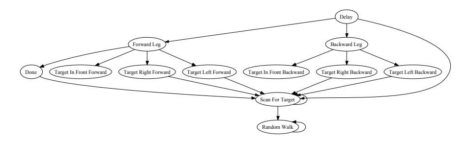
An additional advantage of using a formalized state representation language with markup in the code is that it is possible to generate other representations. For example, our state compiler automatically generates a state transition graph. Figure 6 shows the state transition graph for a simple approach task. The robot first approaches a target and then walks away from it.
8 Conclusion
This paper describes the modifications and additions that we made to convert the Kondo KHR-1 humanoid fighting robot kit into a platform for humanoid robotic soccer.
The addition of a Sony Clie PDA NR-70V with a pan and tilt assembly provides visual feedback for the robot. The original embedded controllers of the Kondo KHR-1 robot are used to control the motion. The PDA communicates via a serial line with the robot and is able to start/stop the motions of the robot.
We use a vision-based approach to determine the behaviour of the robot. The robot uses lines on the playing field to localize itself on the playing field and to map objects into the robot's environment.
The development of the complex architecture necessary for an intelligent soccer player is simplified through the use of an XML based meta language for behaviour trees. This meta language makes the pre-conditions, process stack, and state transitions explicit. The XML representation is converted into C code, which can be compiled into efficient code and thus does not introduce computational overhead through its use.
We are currently investigating methods for adding sensors (e.g., accelerometers, gyroscopes, and force feedback) that provide feedback about the balance of the robot. Even though active balancing is not necessary for a robot playing soccer on an even surface, it is at the heart of humanoid robotics research and is necessary to build robots that are able to move over uneven surfaces. This requires a reprogramming of the PIC micro-controllers used in the Kondo KHR-1 controller boards.
References
- Jacky Baltes and Thomas Bräunl. HuroSot Laws of the Game. University of Manitoba, Winnipeg, Canada, May 2004. http://www.fira.net/hurosot.
- Jacky Baltes and Patrick Lam. Design of walking gaits for tao-pie-pie, a small humanoid robot. Advanced Robotics, 18(7):713–716, August 2004.
- RoboCup Federation. Robocup humanoid league 2002. WWW, November 2001. http://www.robocup.org/regulations/humanoid/rule humanoid.htm.
- K. Y. Hough. Mehod and means for recognizing complex patterns. U.S. Patent 3069654, 1962.
- Jong-Hwan Kim, Dong-Han Kim, Yong-Jae Kim, Kui-Hong Park, Jae-Ho Park, Choon-Kyoung Moon, Jee-Hwan Ryu, Kiam Tian Seow, and Kyoung-Chul Koh. Humanoid robot hansaram: Recent progress and developments. JACIII, 8(1):45–55, 2004.
- Roger Y. Tsai. An efficient and accurate camera calibration technique for 3d machine vision. In Proceedings of IEEE Conference on Computer Vision and Pattern Recognition, pages 364–374, Miami Beach, FL, 1986.
- Fuminori Yamasaki, Tatsuya Matsui, Takahiro Miyashita, , and Hiroaki Kitano. Pino the humanoid: A basic architecture. In Peter Stone, Tucker Balch, and Gerhard Kraetszchmar, editors, RoboCup-2000: Robot Soccer World Cup IV, pages 269–278. Springer Verlag, Berlin, 2001.
- Ruixiang Zhang, Prahlad Vadakkepat, Chee-Meng Chew, and Janesh Janardhanan. Mechanical design and control system configuration of a humanoid robot. In Proc. of 2nd Int. Conf. on Computational Intelligence, Robotics and Autonomous Systems (CIRAS 2003), Singapore, 15 - 18 December 2003.
- Changjiu Zhou and Pik Kong Yue. Robo-erectus: a low-cost autonomous humanoid soccer robot. Advanced Robotics, 18(7):717–720, 2004.