Humanoid Team Humboldt Team Description 2006
Manfred Hild, Matthias Jüngel, Michael Spranger
Institut für Informatik, LFG Künstliche Intelligenz, Humboldt-Universität zu Berlin, Unter den Linden 6, 10099 Berlin, Germany
http://www.humanoidteamhumboldt.de
Abstract This document describes the current hardware and software of the robot system developed by the Humanoid Team Humboldt for the RoboCup competitions to be held in Bremen 2006. The robots are based on a construction kit, which has been significantly extended to serve as a platform for research and competition. The construction kit is enriched by sensors like cameras and acceleration sensors. The existent processing power is expanded by a PDA as well as microprocessors that can be distributed over the body. The paper also explores the developed control software, including the perceptional, modeling, behavioral, and motion controlling components. Mechanical, electrical, and software design are discussed.
1 Introduction
The Humanoid Team Humboldt was founded in 2005, as part of the Artificial Intelligence Lab at the Humboldt-Universität zu Berlin, which has a long and successful history in RoboCup competitions. The Lab is the home of the Agent Team Humboldt (World Champion in the Simulation League 1997 and Vice World Champion in 1998 and 2004), as well as the Aibo Team Humboldt. The Aibo Team Humboldt which can be seen as a predecessor of the Humanoid Team Humboldt is founding member of the GermanTeam [1, 4, 17, 16], which won the RoboCup competitions in the Four-legged League in 2004 and 2005. The Aibo Team Humboldt won the German Open in the Four-legged League two times. The Humanoid Team Humboldt can leverage existent human ressources, knowledge and experience of the existent RoboCup community at the Artificial Intelligence Department at Humboldt-Universität zu Berlin.
While a lot of tasks have been solved regarding perception, modeling and behavior of autonomous systems, one of the biggest problems regarding the RoboCup vision of 2050 [3, 2], namely two legged locomotion, still poses significant problems to researchers world wide. The Humanoid Team Humboldt tries to integrate existing research results from the simulation and the Fourlegged League, as well as results coming from neuro-dynamic research to achieve an intelligent humanoid autonomous system.
2 RobotDesign
[This section contains only subsections]
2.1 Mechanical Design
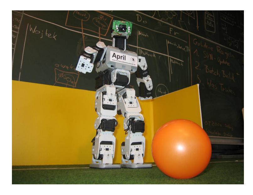
All four robots of the Humanoid Team Humboldt are based on the Bioloid Robot Construction Kit produced by Robotis Inc., Korea. The kit consists of sensomotoric actuators (Dynamixel AX-12), a central processing unit (CM-5), and several universal frame construction pieces. Apart from the basic body construction, not all robots use the same mechanical configuration. Some of which use the built-in camera of a PDA mounted in front of the robot's upper torso, whereas others are equipped with a pan-and-tilt camera module as shown in figure 1. The upper torso contains the battery pack, the central processing unit, a PDA (Pocket Loox, Fujitsu-Siemens) with a (built-in) camera.
Depending on the configuration, each robot has between 19 and 21 degrees of freedom, six per leg, three per arm, one between hip and upper torso, and optional two additional degrees of freedom in the camera's pan-and-tilt module. The robot's size is 42cm and the overall weight is 2,1kg. The whole system is driven by a 9.6V, 2500mAh battery pack, only the PDA has its own battery. A bus systems delivers the power to each submodule, including the pan-and-tilt camera and additional sensor modules (see section 2.3).
2.2 Actuators
All joints are built using the Dynamixel AX-12 actuator. This actuator is a smart, modular actuator that incorporates a gear reducer, a precision DC motor and a control circuitry with networking functionality, all in a single package. Despite its compact size, it can produce high torque and is made with high quality materials to provide the necessary strength and structural resilience to withstand large external forces. It also has the ability to detect and act upon internal conditions such as changes in internal temperature or supply voltage.
One of the actuator's advantages over standard servos is the high speed bus system, the comparably high operating voltage (up to 12V), and the sensory feedback. The most important parameters are:
- Weight: 55 g
- Gear Reduction Ratio: 1/254
- Max Holding Torque: 16.5 kgf.cm (@10V)
- Speed: 0.196 sec/60 degrees (@10V)
- Resolution 0.35 degrees
Within a forthcoming robot body design revision, the two AX-12 actuators of the pan-and-tilt camera module may be replaced by lightweight miniature servos.
2.3 Sensors
At the present state (February 15th, 2006) there are three types of sensory sources:
- Camera subsystem
- Sensory feedback of the actuators
- Acceleration data
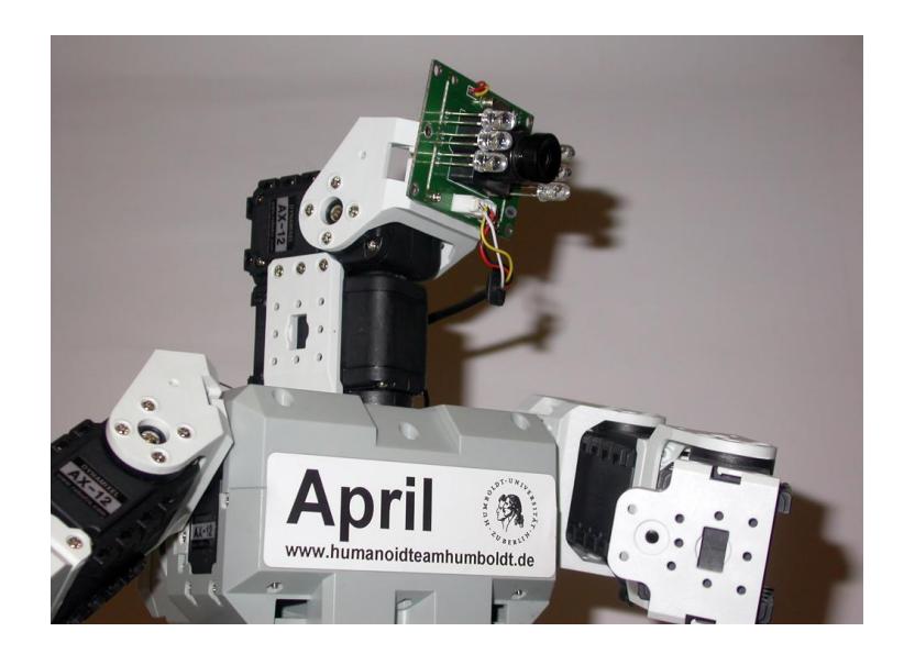
The camera subsystem consists of the PDA-built-in camera (12 fps, 640x480 pixels, using YUV422 packed format and a suitable SDK), or a separate camera module, the video signal of which is digitized by a frame grabber (FlyGrabber, connected per CompactFlash interface). A detailed view of this setting is given in figure 2.
The sensory feedback of the actuators includes the present joint angle, the present motor speed, and the present load. For diagnostic purposes and safety processing also monitoring of the supply voltage and motor temperature is possible.
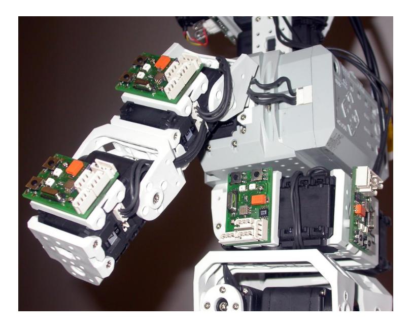
Supplementary acceleration data is acquired by Humanoid Team Humboldt's AccelBoards, which provide a preprocessed signal from Analog Devices' ADXL213 dual axis acceleration sensor. The AccelBoards can easily be mounted at various positions and orientations onto the robot's body, as shown in figure 3.
Sensory data from the AccelBoards is useful to detect different robot poses, especially if combined with the actuator's angle values. This facilitates the decision of the appropriate stand up movements, once the robot has been overthrown by external forces. The AccelBoards seamlessly integrate into the existing robot's bus system.
2.4 Processors
Two main processors operate in parallel. The PDA uses an Intel PXA272 running at 520 MHz and executes vision, modeling, and behavior processes. The CM-5 uses an Atmel ATmega128 running at 16 MHz and executes motion processes.
In addition, each AccelBoard has free processing power left, which can be used for calculation of motion data.
2.5 Inter-Processor-Communication
The PDA, the Dynamixel units, the main processor and the sensor boards are connected via a bus system. The PDA and the CM-5 are connected via RS232 (full duplex). The communication between the CM-5, the sensor boards and the Dynamixel units is done using RS485 (half duplex, asynchronous, 1 MBaud). For the communication between the PDA and the CM-5 a simple protocol is used which sends walk requests and commands for the pan-tilt unit of the head to the CM-5. The CM-5 generates motion patterns and writes the desired joint data to the Dynamixel units. All sensor boards and motors send current sensor readings back to the bus. The CM-5 calculates odometry data and sends it back to the PDA. The protocol that is used on the RS485 bus is defined by the communication protocol of the Dynamixel units. The sensor boards use the same protocol.
3 Control System
A lot of the control system structure has been adopted by the GermanTeam software architecture. Components that have been successfully used in the Fourlegged League, were adopted to suit the needs of humanoid robots. This includes the vision subsystem, large parts of the probabilistic modeling scheme, as well as the behavior architecture and specification scheme [1, 4, 17, 16].
The control system is structured into tasks. Tasks identified include vision, modeling, behavior and motion. The tasks vision, modeling and behavior are each encapsulated by a module. The Module and Solution architecture [15] is a scheme for developing cognitive systems that was introduced by the German-Team. A module is comprised of an interface, which every solution for the task must implement. Software components or solutions that implement a certain task may be individually tested. The runtime system allows for switching solutions at runtime. The system manages the state of all possible solutions and all switched on solutions.
The control system is also roughly structured by the hardware design. While a number of modules are running on the PDA, including the vision, modelling and behavior control system, the motion control system is distributed over the CM-5 processor and the AccelBoards.
3.1 Vision
The vision system is scan-line based which means that only pixels along scan lines are analyzed. The scan lines are aligned to the horizon which can be calculated using the sensor readings from the Dynamixel motors and the acceleration boards. Scan lines are sparse near the horizon as far distant objects are smaller and closer to the horizon. The exact position of objects in the image is determined using so called specialists which are modules that use the full resolution of the image to determine the borders of the objects. The vision system uses color classification and edge detection methods for object recognition. [7][11][12][18]
3.2 Modeling
The WorldModel module is responsible for accumulating information from the sensors over time and incorporating all information from the vision module and the other sensors into one integrated consistent view of the world. The methods used here are well known and often used methods, which include particle filters for self localization as well as kalman filters and rao-blackwellised particle filters for modeling the ball.
Self Localization One of the most successfully applied approaches to the problem of estimating a robots position and orientation is called Monte-Carlo-Localization, a probabilistic approach, in which the current location of the robot is modeled as the density of a set of particles. The particles consist of a robot pose, a vector representing the robot's x/y-coordinates in millimeters and its rotation θ in radians. The Markov-localization method requires both an observation model and a motion model. The observation model describes the probability for taking certain measurements at certain locations. The motion model expresses the probability for certain actions to move the robot to certain relative postures. The localization approach works as follows: first, all particles are moved according to the motion model of the previous action of the robot. Then, the probabilities for all particles are determined on the basis of the observation model for the current sensor readings, like bearings on landmarks calculated from the actual camera image. Based on these probabilities, the so-called resampling is performed, moving more particles to the locations of particles with a high probability. Afterwards, the average of the probability distribution is determined, representing the best estimation of the current robot pose. Finally, the process repeats from the beginning. A detailed description of the system can be found in [18]. The extension made to the particle filter proposed by parts of our group are published in [9, 10, 8]
Ball Modeling It is of great importance for all players to keep track of the position of the ball even if they are not able to see it from where they are. Therefore, a model of the ball is created including the ball's position and speed. The ball's position is derived geometrically from the seen ball in the image, taking into account the robot's pose. The ball speed is calculated from the current and the last ball position perceived. To reduce the measurement's noise a Kalman filter is applied to ball position and speed derived from the ball in the image. The ball modeling system is described in [16, 5].
3.3 Behavior
The module BehaviorControl is responsible for decision making based on the world state, the motion request that is currently being executed by the motion modules, and the team messages from other robots.
For modeling and specification of the behavior control system the Humanoid Team Humboldt uses the Extensible Agent Behavior Specification LanguageXABSL architecture as well as some improvements (YABSL) made by the GermanTeam in the Four-legged League. XABSL and its improvements have proven to be an efficient, complexity reducing way of modeling behavior control. [13, 14] give a detailed view of this system.
3.4 Motion
For motion control two concepts are distinguished: walking and special actions like kicks and getup motions. Special actions are defined using key frames. These key frames can be edited very fast using our tool RobotControl. For walking we investigate different methods. Some of them are pattern generator driven like approaches based on inverse kinematics or fourier series expansion [6] others try to include sensor readings like swing/stance networks.
3.5 Debugging Tools
The Humanoid Team Humboldt is developing an integrated debugging tool, called RobotControl, which tries to integrate different needs of robot control software developers. RobotControl has capabilities for debugging higher level cognitive algorithms like perception. This includes mechanisms for manipulating and viewing images for debugging purposes, as well as providing drawing primitives for easy drawing into representations of images and fields. Simple time measurement as well as data manipulation methods are provided. It is also possible to connect to lower level micro-controllers and individual sensors.
4 Future Plans
The design of our robots' hard- and software in this year is dominated by a very pragmatic approach: to be able to compete in RoboCup competitions as quick as possible. Future plans include modifications of the mechanical design of the robots as well as improvements of the control system. We have already started with preparations to remove the CM-5 as a central processor. The motor control program will be distributed to the processors of the sensor boards. To create more dynamic movements we plan to increase the number of sensors. We want to investigate which parts of the body are most suitable to attach acceleration and pressure sensors. Another planned change of the design of our robots is to distribute the battery to different parts of the body to optimize the balance of the robots.
Compared to our four legged robots there arise new challenges in perception. The calculation of the camera matrix is less precise than on the Aibo robots due to the many degrees of freedom of the humanoid robot. Thus we will investigate how to learn relations between perceived objects and the robot based on the robots joint and acceleration sensors. Additionally humanoid robots are a perfect platform to test the interaction between mechanisms for object modeling and gaze control.
References
- R. Brunn, U. Düffert, M. Jüngel, T. Laue, M. Lötzsch, S. Petters, M. Risler, T. Röfer, K. Spiess, and A. Sztybryc. Germanteam 2001. In A. Birk, S. Coradeschi, and S. Tadokoro, editors, RoboCup 2001: Robot Soccer World Cup V, volume 2377 of Lecture Notes in Artificial Intelligence, pages 705–708, Seattle, WA, 2002. Springer. more detailed in GermanTeam RoboCup 2001. Technical Report (41 pages, http://www.tzi.de/kogrob/papers/GermanTeam2001report.pdf).
- H.-D. Burkhard, D. Duhaut, M. Fujita, P. Lima, R. Murphy, and R. Rojas. The road to robocup 2050. IEEE Robotics and Automation Magazine, 9(2):31–38, 2002.
- H.-D. Burkhard and H.-A. Marsiske. Endspiel 2050 Wie Roboter Fußball spielen lernen. Heise, 2003.
- U. Düffert, M. Jüngel, T. Laue, M. Lötzsch, M. Risler, and T. Röfer. Germanteam 2002. In G. A. Kaminka, P. U. Lima, and R. Rojas, editors, RoboCup 2002: Robot Soccer World Cup VI, volume 2752, pages 114–124. Springer, 2003. more detailed in GermanTeam RoboCup 2002. Technical Report (178 pages, http://www.tzi.de/kogrob/papers/GermanTeam2002.pdf).
- D. Göhring. Modellierung bewegter Objekte durch mobile Agenten: Diplomarbeit. Master's thesis, Institut für Informatik, Humboldt-Universität zu Berlin, 2004.
- J. Hoffmann and U. Düffert. Frequency space representation and transitions of quadruped robot gaits. In Proceedings of the 27th conference on Australasian computer science, volume 26, pages 275 – 278. Australian Computer Science Society, Inc., 2004.
- J. Hoffmann, M. Jüngel, and M. Lötzsch. A vision based system for goal-directed obstacle avoidance. In D. Nardi, M. Riedmiller, C. Sammut, and J. Santos-Victor, editors, 8th International Workshop on RoboCup 2004 (Robot World Cup Soccer Games and Conferences), volume 3276, pages 418–425. Springer, 2005.
- J. Hoffmann, M. Spranger, D. Göhring, and M. Jüngel. Negative information and proprioception in monte carlo self-localization for a 4-legged robot. Nineteenth International Joint Conference on Artificial Intelligence (IJCAI), 2005. Workshop on Agents in Real-Time and Dynamic Environments.
- J. Hoffmann, M. Spranger, D. Göhring, and M. Jüngel. Exploiting the unexpected: Negative evidence modeling and proprioceptive motion modeling for improved markov localization. In I. Noda, A. Jacoff, A. Bredenfeld, and Y. Takahashi, editors, 9th International Workshop on RoboCup 2005 (Robot World Cup Soccer Games and Conference). Springer, 2006.
- J. Hoffmann, M. Spranger, D. Göhring, and M. Jüngel. Making use of what you don't see: Negative information in markov localization. In Proceedings of the 2005 IEEE/RSJ International Conference of Intelligent Robots and Systems (IROS). IEEE, 2006.
- M. Jüngel. Using layered color precision for a self-calibrating vision system. In D. Nardi, M. Riedmiller, C. Sammut, and J. Santos-Victor, editors, 8th International Workshop on RoboCup 2004 (Robot World Cup Soccer Games and Conferences), volume 3276, pages 209–220. Springer, 2005.
- M. Jüngel, J. Hoffmann, and M. Lötzsch. A real-time auto-adjusting vision system for robotic soccer. In D. Polani, A. Bonarini, B. Browning, and K. Yoshida, editors, 7th International Workshop on RoboCup 2003 (Robot World Cup Soccer Games and Conferences), volume 3020, pages 214–225. Springer, 2004.
- M. Lötzsch. Xabsl: A behavior engineering system for autonomous agents: Diploma thesis. Master's thesis, Institut für Informatik, Humboldt-Universität zu Berlin, 2004.
- M. Lötzsch, J. Bach, H.-D. Burkhard, and M. Jüngel. Designing agent behavior with the extensible agent behavior specification language XABSL. In D. Polani, B. Browning, A. Bonarini, and K. Yoshida, editors, RoboCup 2003: Robot Soccer World Cup VII, volume 3020. Springer, 2004.
- T. Röfer. An architecture for a national robocup team. In G. A. Kaminka, P. U. Lima, , and R. Rojas, editors, RoboCup 2002: Robot Soccer World Cup VI, volume 2752, pages 417–425. Springer, 2003.
- T. Röfer, R. Brunn, I. Dahm, M. Hebbel, J. Hoffmann, M. Jüngel, T. Laue, M. Lötzsch, W. Nistico, and M. Spranger. GermanTeam 2004: The German national RoboCup team. In D. Nardi, M. Riedmiller, C. Sammut, and J. Santos-Victor, editors, RoboCup 2004: Robot Soccer World Cup VIII, volume 3276 of Lecture Notes in Artificial Intelligence. Springer, 2005. Full team report can be downloaded at http://www.germanteam.org/.
- T. Röfer, I. Dahm, U. Düffert, J. Hoffmann, M. Jüngel, M. Kallnik, M. Lötzsch, M. Risler, M. Stelzer, and J. Ziegler. Germanteam 2003. In D. Polani, B. Browning, and A. Bonarini, editors, RoboCup 2003: Robot Soccer World Cup VII, volume 3020 of Lecture Notes in Artificial Intelligence, pages 114–124, Padova, Italy, 2004. Springer. more detailed in GermanTeam RoboCup 2003. Technical Report (199 pages, http://www.germanteam.org/GT2003.pdf).
- T. Röfer and M. Jüngel. Vision-based fast and reactive monte-carlo localization. In D. Polani, A. Bonarini, B. Browning, and K. Yoshida, editors, Proceedings of the 2003 IEEE International Conference on Robotics and Automation (ICRA), pages 856–861. IEEE, 2003.