JEAP Team Description
Norbert Michael Mayer, Masaki Ogino, Rodrigo da Silva Guerra, Joschka Boedecker, Sawa Fuke, Hiroyuki Toyama, Ayako Watanabe, Kazuhiro Masui, Minoru Asada
Dept. of Adaptive Machine Systems, Osaka University
Abstract We present here the structure of our humanoid robot soccer team JEAP. We use a heterogenous set of commercial humanoid robots that are havily customized from their original design. For this RoboCup we are also ordering a new custo m designed humanoid whose specifications are already included in this paper. The task of controlling these robots is faced through the use of a unified software approach applicable for all types of humanoid robots. In this team description paper we focus on the hardware and the behavioral system.
1 Introduction
The JEAP team origins from the Senchans team[5] that participated in competitions of the humanoid league since its beginning in the year 2002. The name JEAP is an acronym for JST ERATO Asada Project and refers to a new ERATO project. The ER-ATO project is concerned with the study of Synergistic Intelligence through the use of cognitive developmental approaches to robotics. named Synergistic Intelligence is starting in April 2006. Our team is embedded into this project.
Significant changes to previous years characterized last years Humanoid League competition. One can see an evolutionary process towards certain technologies. The typical winning robot of this years competition is a small robot that uses servo motors as actuators and a simple but robust control structure.
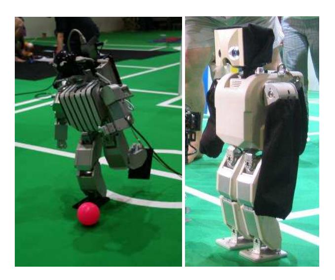
Thus, also the JEAP team considers now the servo-actuated robots and integrates them into their software environment. For pictures of two of our servo based robots see figure 2 (HEP is still under development, so no image is available for the time being). The result is a rather heterogenous environment of robots. We outline the situation on the hardware side in section 2. In the following section (section 3) we discuss our present high level behavior system. Finally, we report about the walking algorithm in section 5.
2 Heterogenous Robot Hardware
The design concepts of the robots used in the Humanoid League are converging. As with other leagues, the teams tend to copy design concepts from successful teams in the previous years. For example, we see more and more robots that are controlled by servo motors. We use several types of robots and thus plan to introduce several types in the RoboCup 2006 competition. The platforms are Hoap 2 and Hoap 3 from Fujitsu Inc.,
The cameras and computers are planned to be interchangeable between the robots thus the final configuration may be a permutation of the Table outlined below.
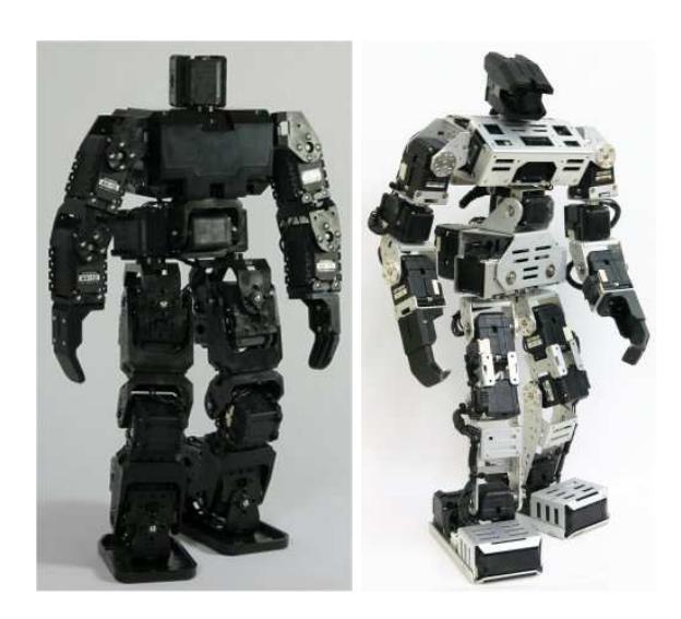
Table 1. Robot types and specifications to be used in the RoboCup 2006 competition. Abbreviations are: C. (camera), A. (acceleration sensor), T. (touch sensor), Dyn. (Dynamixel).
| Name | Hoap 2 | Hoap 3 | Bioloid | Cycloid II | Jeap HEP |
|---|---|---|---|---|---|
| Manufacturer Fujitsu | Fujitsu | Tribotix | Tribotix | VStone | |
| Height | 58cm | 60cm | ≈ 40cm | 41.5cm | 45cm |
| Weight | 7.5kg | 8.3kg | 2.2kg | ≈ 3kg | 4.0kg |
| Speed of W. | 1.2m/min | 1.2m/min | ≈ 1m/min | ≈ 1m/min | ≈ 1m/min |
| DOF | 25 | 28 | 19 | 23 | 24 |
| Actuators | DC Motors | DC Motors | Dyn. AX-12 Dyn. DX-117 Dyn. DX-117 | ||
| Manufacturer Fujitsu | Fujitsu | Tribotix | Tribotix | Tribotix | |
| Torque | up to 450 Ncm up to 450 Ncm ≈ 150Ncm ≈ 350Ncm | ≈ 350Ncm | |||
| Speed | 1000 deg/s | 1000 deg/s | 300 deg/s | 500 deg/s | 500 deg/s |
| Sensors | C., A., T. | C., A., T. | C. | C. | C.,A. |
| Camera res. 640x480 | 640x480 | 176x255 | 176x255 | 640x480 | |
| Frame rate | 30fps | 15-30fps | <50fps | <50fps | 20fps |
| Type | Firefly | Quickcam | CMUCam | CMUCam | Quickcam |
| CPU type | PC 104 | PC 104 | Gumstix | Gumstix | PNM-SG3, SH2 |
| CPU speed | 800MHz | 800 MHz | 400MHz | 400 MHz | 800MHz |
3 Object Oriented Framework
Despite the heterogenous structure of the hardware we are planning to control the behavior of the robots by one type of behavior control architecture. The critical point is the interface between the behavior and the low level commands that depend specifically on the hardware of the robot type and has to be designed fro each robot in a different way.
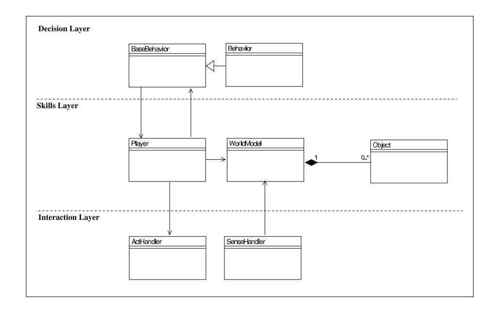
The structure of the agent code for our team consists of a very flexible framework for behavior development which had been borrowed from the veteran simulation league team RoboLog [1]. There have been several efforts for the approximation among the leagues and re-use of knowledge from simulation to humanoids and vice-versa (for instance see [4],[3] and [2]). The figure 3 shows a simplified UML representation of this architecture, where three distinct layers are discriminated:
- Interface layer: Handles all sensory information input to the robot as well as it handles the control signals sent to the lower level controllers of motor behaviors.
- Skills layer: Here information is parsed and processed in order to keep updated the models of the external world.
- Decision layer: This layer uses information provided by the skills layer for determining the best action in each situation.
3.1 Plug-in architecture
This modular design allows easy extensibility and portability. As could be seen in the section 2, our team has a varied range of different platforms. The robots have different mass distribution, different CPUs, different types of actuators and sensors, and different degrees of freedom (DOFs) to cite a few. Nevertheless, our framework is malleable enough for allowing the re-use of code among these different machines.
3.2 Forwarders
It is not always possible to attach a display in these humanoid robots, and even doing so, debugging of the code is almost infeasible due to the huge amount of flowing messages that would be required to be displayed. Moreover, it is useful, sometimes, to simply suppress debug information or to forward this information to a file, etc. The forwarders plug-in defines an standard interface to which all the debug information is sent in the form of streams. By doing so it becomes no longer necessary to recompile the code just in order to suppress or redirection the debugging data.
3.3 Parameter parsing
The parameter parsing feature is a handy solution for the easy manipulation of various settings with no need for recompilation of source code. The format for the parameter files allows the nesting of sections into several levels, which can be parsed later in the code. The code bellow shows a small section of the parameters file and an example of the code for retrieving such information:
...
camerasettings {
    device = /dev/video1394;
    driver = ieee1394;
    focallength = 500;
    framerate = 15;
    picture {
        ieee1394 {
             exposure = 319;
             gain = 200;
             saturation = 126;
             shutter = 7;
             whitebalance {
                 UB = 99;
                 VR = 76;
                 ...
Example of code:
string whitebalanceStr =
  ParamReader.Integer("camerasettings:picture:ieee1394:whitebalance");
Fig. 4. Example of parameter file and the corresponding code for retrieving some value.
4 Behavior
It is very common and straight forward to explicitly design robot behaviors such that the robot pursue a systematic sequence of logical procedures. One example of this type of approach could be, for example, measuring the distance up to the ball with accurately calibrated cameras and then counting the exact number of steps to the such location.
JST Erato Asada Project, our funding organization, is concerned with the study of cognitive developmental processes as they happen in natural beings like man and other animals in general. It is obviously impractical with currently technology to fully approach such a complex problem like playing soccer based on a extremely purist point of view. In a strength for matching our purist approach to the practical needs of the RoboCup competitions we tried to construct the robot behaviors in the most natural way by:
- Choosing a robot centered coordinate system: Instead of having global coordinates of any sort, we explicitly opted for using the agent's self point of view. This brings the drawback of making it difficult for the robot to make decisions based on the relative positions in the field. Despite of that, the use of relative positions to the observer makes it easer to generalize the use of a determined behavior in several situations – same relative positions might repeat in several different locations of the field.
- Describing position of objects in terms of neckangles: We decided not to use newtonian distances for localization of objects. Instead of that we kept all our model of the world in the natural format in which it was acquired: neck angles. Roughly speaking, pan/tilt rotations of the head are transformed into image displacements in terms of pixels and vice-versa. We took a very simplified model of a pinhole for transforming the Cartesian coordinates of blobs in the image plane into pan and tilt angles for the robot. Position of objects outside the current view field were kept for small intervals until the robot moved the neck so as to update positions again.
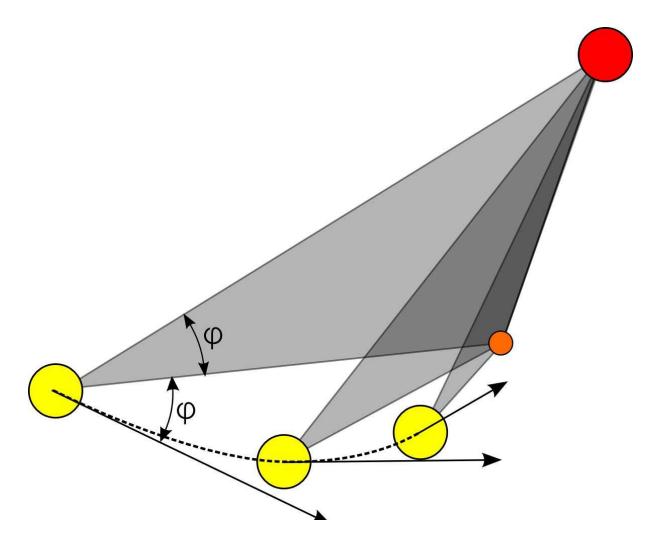
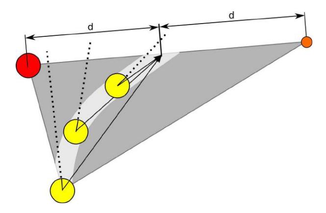
- Translating behaviors in terms of objects alignments and reactive beha viors. The most common soccer playing schemes were described in terms of purely reactive behaviors based as much as possible in very low level sensing. See figures 5 and 6 for some examples. The relative angles are described in terms of neck position giving a realistic embodied description to the nature of each situation.
5 Rhythmic Walking Controller
5.1 A biped robot model
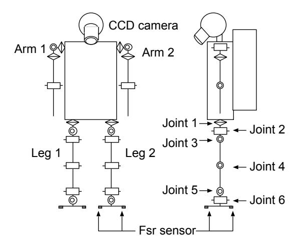
Fig. 7 shows a biped robot model used in the experiment which has a one-link torso, two four-link arms, and two six-link legs. All joints rotate with a single DOF. Each foot has four force-sensing-resistor (FSR) sensors to detect reaction force from the floor, and a CCD camera with a fish-eye lens is attached at the top of the torso.
5.2 A rhythmic walking controller based on CPG principle
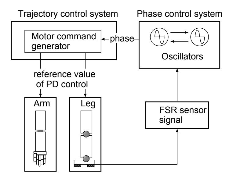
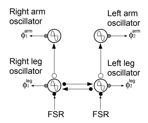
We build a lower-layer controller based on one proposed by Tsuchiya et al. [6]. The controller consists of two sub-controllers: a trajectory controller and a phase controller (see Fig. 8). The trajectory controller outputs the desired trajectory of each limb depending on the phase that is given by the phase controller. The phase controller consists of four oscillators, each of which is responsible for the movement of each limb (see Fig. 9). Each oscillator changes its speed depending on the touch sensor signal, and the effect is reflected on the oscillator in each limb. As a result, the desired trajectory of each joint is adjusted so that the global entrainment of dynamics between the robot and the environment takes place. In the following, the details of each controller are given.
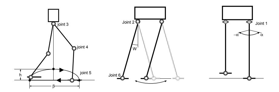
Trajectory controller The trajectory controller calculates the desired trajectory of each joint depending on the phase given by the corresponding oscillator in the phase controller. Four parameters characterize the trajectory of each joint as shown in Fig. 10. For joints 3, 4 and 5, which coincide with pitch axis, the desired trajectory is determined so that in the swing phase the foot trajectory draws a ellipse that has the radii h in the vertical direction and β in the horizontal direction, respectively. For joints 2 and 6, which coincide with roll axis, the desired trajectory is determined so that the leg tilts from −W to W relative to the vertical axis. The amplitude of the oscillation, α, determines the desired trajectory of joint 1. The desired trajectories are summarized by the following functions:
$$\theta_1 = \alpha \sin(\phi),$$
$$\theta_2 = W \sin(\phi),$$
$$\theta_i = f_i(\phi, h, \beta), \quad (i = 3, 4, 5)$$
$$\theta_6 = -W\sin(\phi).$$
The detail of f^i is explained in the Appendix. Among the four parameters described above, α, which determines the walking step length, and β, which determines the walking direction, are selected as rhythmic parameters of walking. Although these parameters characterize approximate direction and step length, they do not determine the resultant walking as precisely because of slippage between the support leg and the ground. These parameters are learned in the upper-layer learning module, which is described in 3.
Phase controller The phase controller sets the phase that determines the desired value of each joint. The phase controller consists of two oscillators, φ^R and φ^L, for the right and left leg, respectively. The dynamics of each oscillator is determined by the basic frequency, ω, the interaction term between two oscillators, and the feedback signal from the sensory information,
$$\dot{\phi}_L = \omega - K(\phi_L - \phi_R - \pi) + g_L$$
$$\dot{\phi}_R = \omega - K(\phi_R - \phi_L - \pi) + g_R.$$
The second term on the RHS in the above equations ensures that the oscillators have opposite phases. The third term, feedback signal from sensor information, is given as follows:
$$g_{i} = \begin{cases} K'Feed_{i} & (0 < \phi < \phi_{C}) \ -\omega(1 - Feed_{i}) & (\phi_{C} \le \phi < 2\pi) \end{cases}$$
$$i = {R, L},$$
where K′, φ^C and Feed^i denote feedback gain, the phase when the swing leg contacts with the ground, and the feedback sensor signal, respectively. Feed^i returns 1 if the FSR sensor value of the corresponding leg exceeds a certain threshold value, otherwise 0. The third term in (5) and (6) ensures that the mode switching between the swing phase and the support phase happens appropriately according to the ground contact information from the FSR sensors. In this paper, the values of parameters are set as follows: φ^C = π [rad], ω = 5.23 [rad/sec], K = 15.7 and K′ = 1.
6 Discussion
We present in this work the design structure of our robots and the software environment. We regard the new heterogenous structure of our robot hardware as a special challenge. The further work is to complement our development environment by a simulator tool. Our intention is here not to develop an own simulator. Since a part of our team is involved in the simulation league one of our special concerns is to make use synergies that may evolve from this. As part of this idea we want to help to bring the simulation league and the humanoid league closer together (see also [2, 3]).
7 Acknowledgments
We thank Oliver Obst for helpful hints discussions. In addition, we thank the Handai FRC, Kaken and the ERATO project for their financial support.
References
- Heni Ben Amor, Joschka Boedecker, and Rodrigo da Silva Guerra Yuichi Matsumoto. Team Description RoboLog. In RoboCup Simulation League Team Description Paper, 2006.
- Joschka Boedecker, Rodrigo da Silva Guerra, Norbert Michael Mayer, Oliver Obst, , and Minoru Asada. 3D2Real: Simulation League Finals in Real Robots. In RoboCup Symposium, 2006. (submitted).
- Joschka Boedecker, Norbert Michael Mayer, Masaki Ogino, Rodrigo da Silva Guerra, Masaaki Kikuchi, and Minoru Asada. Getting closer: How Simulation and Humanoid League can benefit from each other. In Proceedings of the 3rd International Symposium on Autonomous Minirobots for Research and Edutainment (AMiRE), 2005.
- Rodrigo da Silva Guerra, Joschka Boedecker, Norbert Michael Mayer, Shinzo Yanagimachi, Yasuji Hirosawa, Kazuhiko Yoshikawa, Masaaki Namekawa, and Minoru Asada. CITIZEN Eco-Be!: bringing new flexibility for research and education to RoboCup. In Daniele Nardi, Martin Riedmiller, and Claude Sammut, editors, RoboCup 2006: Proceedings of the International RoboCup Symposium. Springer, Berlin, Heidelberg, New York, 2006. to be reviewed.
- Norbert Michael Mayer, Joschka Boedecker, Masaki Ogino, Masaaki Kikuchi, Rodrigo da Silva Guerra, and Minoru Asada. Osaka University Team Senchans 2005. In Proceedings of RoboCup Symposium, 2005.
- K. Tsuchiya, K. Tsujita, K. Manabu, and S. Aoi. An emergent control of gait patterns of legged locomotion robots. In Proc. of the Symposium on Intelligent Autonomous Vehicles, pages 271–276, 2001.