Charrobot - RoboCup Humanoid League 2006
Norberto Velázquez, Salvador Alejandro Velázquez, Juan Guillermo Fitch, Roberto Carlos Ramírez, Daniel Laborin
Panamerican University, Campus Guadalajara
Abstract Here we describe the design and realization of Charrobot , a humanoid robot that plays soccer manufactured by students, able to make several tasks, as walking, identifies objects like a soccer ball and approaches to it and kicks it. Also there will be described not only its primary functions, but all the constraints presented along and characteristics of our design like sizes, components, specifications and design of the structure and electronic system. Because we are presenting two robots, we will specified the two different program codes, one for the player and the other for the goal keeper.
This is the first time we participate in this League and the design we are presenting is totally new.
1 Introduction
From the beginnings of robotic we have been trying to emulate the movements of human beings initiating with some insects movements because of their great functionality and adaptability in certain lands and conditions. The actual challenge of robotic is to equal the mobility of the human being to make movements of great complexity and precision.
With this project we pretend to develop an adaptable prothesis to the legs of a person, with the objective and possibility that an invalid person could walk again and recover great part of he's activities.
We do not have already the design of the prothesis, because this project just begins, in fact the RoboCup competitions will be an opportunity to prove our designs and prototype.
Because of the necessity of automatization, technology and control has been developing because lots of tasks or processes are performed via robots, replacing men and keeping always the simplest and most comfortable way to do things, many ideas can be achieved thanks to these machines.
As robots are flexible enough to develop many or specific challenges, it's design, manufacturing and testing are important points to take care of.
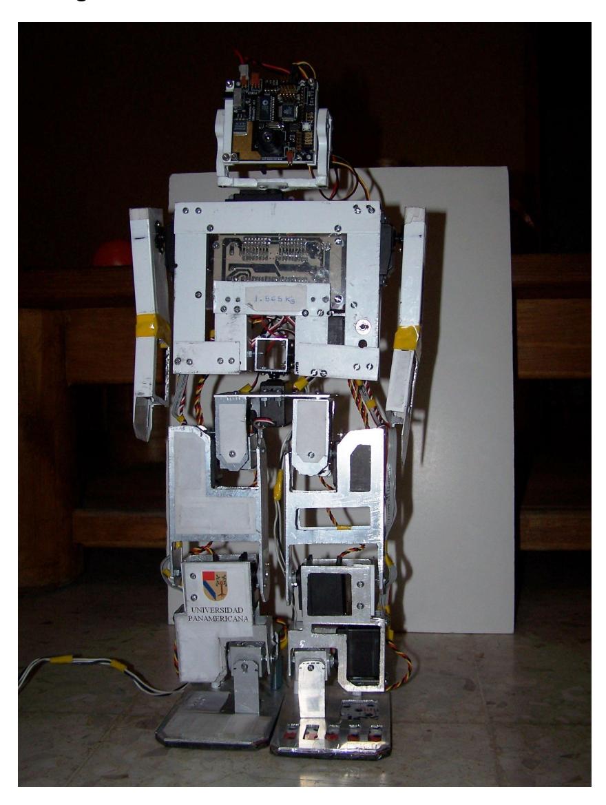
2 Image of the robot
3 Name of the robot
Charrobot
4 Robot height
The height of the robot was determine by (1):
$$H = \min(H_{top} 2.2 \bullet H_{com}) \tag{1}$$
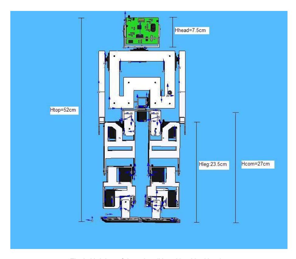
The total height (Htop) of our robot is of 52 cm, and the center of mass (Hcom) is at a distance of 27 cm from the floor. Applying this distances in equation (1), we obtain H.
$$H = \min(52cm, 2.2 \bullet 27cm)$$
Because H is 52 cm and contemplating that our robot is participating in the Kid Size Category it fulfills the next condition (2).
$$30cm \le H \le 60cm \tag{2}$$
$$30cm \le 52cm \le 60cm$$
5 Size of the robot
Fulfilling with the Humanoid Robots Specifications we will present de general sizes of the robot.
Each foot of the robot must fit in an area of (3):
$$A = \frac{H^2}{22} \tag{3}$$
$$A = \frac{52^2}{22} = 1352cm^2$$
The robot must fit in cylinder diameter of (4):
$$D = \frac{H}{2} \tag{4}$$
$$D = \frac{52}{2} = 26cm$$
The arms extensión maximally streched in horizontal direction is less than (5):
$$1.2 \bullet H \tag{5}$$
$$1.2 \bullet 52 = 62.4$$ cm
The robot does not possess a configuration where it is extended longer than (6):
$$1.5H\tag{6}$$
$$1.5 \bullet 52 = 78cm$$
The length of the legs Hleg=23.5, including the feet, satisfies (7):
$$.04 \bullet H \le H_{leg} \le .6H \tag{7}$$
$$.04 \bullet 52cm \le 23.5 \le .6 \bullet 52cm$$
The height of the head Hhead= 7.5cm, including the neck, satisfies (8):
$$0.1 \bullet H_{head} \le 0.2 \bullet H \tag{8}$$
$$0.1 \bullet 7.5cm \le 0.2 \bullet 52cm$$
6 Weight of the robot
The weight of the robot is of 2.1 kg and was design so that the torque of our motors could move all the joints in an efficient way. We decide to cut some of the unnecessary aluminum parts that will help us reduce weight without sacrificing resistance joints.
We also distributed the weight of the robot so that the center of mass will help us achieve the necessary height so that this will be in an specified range.
7 Number of degrees of freedom (DOF)
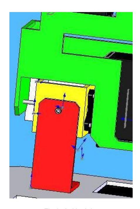
The total number of degrees of freedom in our robot is 16. In each one of the joints of the robot we decided to put a servo motor that each one will represent a (DOF).
7.1 Actuators
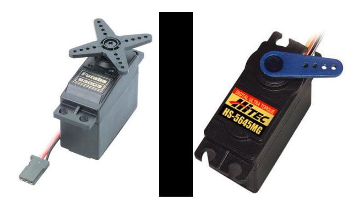
The total number of actuators in our design is of 16 servo motors. Our robot in conform of two different torque servo motor. The first one is a FUTABA S3003 with a torque of 3kg-cm and the second one is a HITEC HS-5645MG with a torque of 12 kg-cm, both with a speed of 60°/0.19 sec. We decide to use the HITEC HS-5645 MG of 12 kg-cm of torque in the
lowest part of the robot, because is where he needs more force to walk,
kick and stand up in case of falling. By the opposite we use the FUTABA S3003 with a torque of 3kg-cm in the upper part of the robot.
Head: 2 servo motor, FUTABA S3003
Arms (2): 1 servo motor in each arm, FUTABA S3003
Waist: 2 servo motors, FUTABA S3003
Ingle: 4 servo motor, the HITEC HS-5645 MG
Knee (2): 1 servo motor in each knee, the HITEC HS-5645 MG Ankle (4): 2 servo motor in each ankle, the HITEC HS-5645 MG
8 Communication
The robot was designed to act autonomously during the competition, so no external power supplies, teleoperation, of any kind of remote control are used on the system. The start and stop signals are sent them manually to the robot using the control panel; it was programmed to give the robot handler a few seconds to leave the field before it starts to move.
In this occasion, being our first participation and because of the short time in which we developed the project, we did not use a remote control system; without blocking that the robot fulfills with the established rules since it must be able to play even without a wireless network or a low signal of it. However , this will not interference with the robot's performance and fulfillments of the rules.
The communication between the robots, base in our design, was not necessary because each of the robots has specific duties and therefore the programming of each one was independent.
9 Processing boards
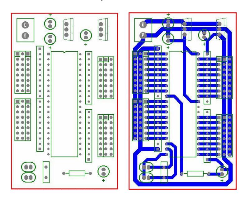
It only counts of a processor board that is the brain and was design and construct by members of the team. This contains the microcontroller, he's oscillating circuit, two voltage regulators and connection for the feeding and the control signal of the 16 servomotors. Next we present the distribution of the electronic components of the board.
9.1 Battery
Analyzing the electronic system, we saw that the peak current of the robot its 2 amperes and the operational current its 0.8 amperes, therefore the robot is using four rechargeable AA batteries of 1.2 volts each one and they work at 1200mAh.

10 Control
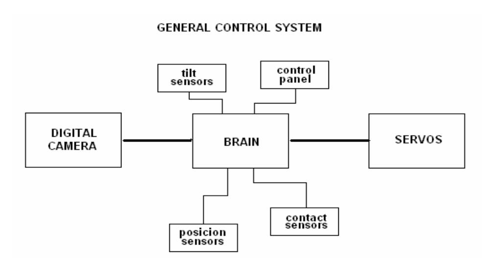
The control system of the robot is basically a microcontroller in which several sensors are connected that provide necessary information to assure the correct operation. The brain is microcontroller AT89S8252 of the 8051 family of ATMEL. We choose this element because of his low price, easy programming and because of the four ports of 8 bits of entrance and exits for handling data. The program code its shown in appendix because the program was made in assembler language.
Below is a diagram of the elements that conform it and we will explain its operation ahead.
10.1 Digital Camera
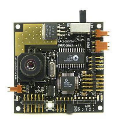
The main sensor placed on the robot's head is the camera CMUcam2 and it consists of a SX52 microcontroller interfaced with an OV7620 Omnivision CMOS camera on a chip that allows simple high level data to be extracted from the camera's streaming video. The board communicates via a RS-232 or a TTL serial port and has the following functionality:
Track user defined color blobs at up to 50 Frames Per Second*
Track motion using frame differencing at 26 Frames Per Second
Find the centroid of any tracking data
Gather mean color and variance data
Gather a 28 bin histogram of each color channel
Manipulate Horizontally Pixel Differenced Images
Transfer a real-time binary bitmap of the tracked pixels in an image
Arbitrary image windowing
Adjust the camera's image properties
Dump a raw image (single or multiple channels)
Up to 160 x 255 Resolution 1
Supports Multiple Baudrates: 115,200 57,600 38,400 19,200 9,600 4,800 2,400 1,200
Control 5 servo outputs
Slave parallel image processing mode off of a single camera bus
Automatically use servos to do two axis color tracking
B/W Analog video output (PAL or NTSC)
10.2 Tilt sensors
We also used a pair of tilt sensors to detect when the robot fall to the ground or exceed the limit of tilde and this information is used by the microcontroller to decide the actions to take to get up or to keep the balance.
These are just switches who close when certain inclination is reached or when they are in an horizontal position.
10.3 Position and contact sensors
The position sensors are located in the ankle and knee joints of both legs of the robot and are variable resistances that when they are connected to a oscillator circuit, any variation in the doblez of the joint will be represented like a lineal variation of the period and the duty cycle of the exit signals of the oscillators, that will be too introduce to the micro.
The exit signals of the sensors indicate us sufficient precision the position of the legs of the robot with respect to a reference fija that is the stop position. This information its very important when the land where he is walking its irregular since it provides a new reference of the land and this will help maintain the necessary balance to walk in the land.
The contact sensors that are push buttons will be localized under the feet of the robot and when its connected to the brain, they will have like objective to indicate the moment in which the foot of the robot makes contact with any surface.
11 Conclusions
This project was a great experience for all of us in several aspects, and helped us to discover our different capabilities as well as our weaknesses, that we could handle and fix with the teamwork.
The teamwork was our better strength because we had a lot of problems along the project that we had to solve sometimes briefly, and the way we solved them, which we consider the best one, was the teamwork, since although we were divided in two parts; control system and mechanics; we helped each other in difficult situations and we never forgot that we are a team and we all took this project seriously and with the disposition needed, because this is a not easy project and it demands many time and sacrifice, as well as good will after all what happened even the situation of possible contest cancellation, what did not stop us from working.
This project help us to comprehend the different movements of human beings, because we had to analyze carefully how persons move to program our robot an try to imitate the exact movements.
It also help us to understand more about development of prothesis and the advantages that this offers to does people that need to recover their movements.
A very important thing is the fact that we received complete support from our University, part of the budget was supported by them and other resources like electronics and tool labs, computers, software. Another part of the budget was support by the members of the team.
It was a really good thing counting with their help all this time long, what we are very thankful of.
During this project we applied part of the knowledge acquired along the engineering studies, and in some occasions we had to investigate on subjects that didn't know about, and ask for support of some teachers who had the knowledge and the experience to advise us.
12 Appendix
12.1 Program code
ORG 00H

MOV 21H,#41H ;1 ;carga los
registros en la posición cero
MOV 23H,#18H ;2
MOV 25H,#30H ;3
MOV 27H,#4CH ;4
MOV 29H,#26H ;5
MOV 2BH,#82H;10H ;6
MOV 2DH,#31H ;7
MOV 2FH,#42H ;8
MOV 31H,#40H ;9
MOV 33H,#30H ;10
MOV 35H,#2CH ;11
MOV 37H,#12H;82H ;12
MOV 39H,#3DH ;13
MOV 3BH,#26H ;14
MOV 3DH,#6EH ;15
MOV 3FH,#2EH ;16

MOV 41H,21H ;SERVO1 ;CARGO LA POSICIÓN INICIAL PARA EVITAR QUE SE VUELVAN LOCOS AL PRINCIPIO
MOV 43H,23H ;SERVO2
MOV 45H,25H ;SERVO3
MOV 47H,27H ;SERVO4
MOV 49H,29H ;SERVO5
MOV 4BH,2BH ;SERVO6
MOV 4DH,2DH ;SERVO7
MOV 4FH,2FH ;SERVO8
MOV 51H,31H ;SERVO9
MOV 53H,33H ;SERVO10
MOV 55H,35H ;SERVO11
MOV 57H,37H ;SERVO12
MOV 59H,39H ;SERVO13
MOV 5BH,3BH ;SERVO14
MOV 5DH,3DH ;SERVO15
MOV 5FH,3FH ;SERVO16
MOV 75H,#06H ;CARGO LA VEL
LCALL DESPLAZA
MOV 51H,#41H ;QUÉDATE UN MOMENTO
MOV 75H,#0FFH
LCALL DESPLAZA
; EMPIEZA A CAMINAR

MOV 41H,#37H ;1 ;SE INCLINA A LA IZQUIERDA
MOV 43H,#0EH ;2
MOV 4FH,#38H ;8
MOV 5BH,#1CH ;14
MOV 45H,#33H;UN POCO AGACHADO
MOV 75H,#02H
LCALL DESPLAZA

MOV 41H,#2CH ;1 ;SE INCLINA A LA
MOV 43H,#03H ;2 ;SOLO
IZQUIERDA
"A" POSICIONES
MOV 4FH,#2DH ;8
MOV 5BH,#12H ;14
MOV 49H,#2EH ;MUEVE PIE
DERECHO PA DELANTE, 8 POSICIONES
MOV 59H,#45H
MOV 47H,#54H ;MUEVE EL PIE IZQ
PARA ATRÁS 8 POSICIONES
MOV 4DH,#39H
MOV 4BH,#16H; DOBLA UN POCO
"4"POS, LAS RODILLAS
MOV 57H,#7CH
MOV 5DH,#66H ;MUEVE LOS BRAZOS
MOV 5FH,#26H
MOV 75H,#02H ;VELOCIDAD
LCALL DESPLAZA

MOV 41H,#41H ;1 ;PARADITO
MOV 43H,#18H ;2
MOV 4FH,#42H ;8
MOV 5BH,#26H ;14
MOV 45H,#30H;ERGIDO OTRA VEZ
MOV 5DH,#5CH ;MUEVE LOS
BRAZOS
MOV 5FH,#1CH
MOV 4BH,#14H; REGRESA
"2"POS, LAS RODILLAS
MOV 57H,#7EH
MOV 75H,#02H
LCALL DESPLAZA

MOV 51H,#41H ;QUÉDATE UN MOMENTO
MOV 75H,#0AFH
LCALL DESPLAZA

;SEGUNDO PASO

MOV 41H,#4BH ;1 ;SE INCLINA A
LA DERECHA "A" POSICIONES
MOV 43H,#22H ;2
MOV 4FH,#4CH ;8
MOV 5BH,#30H ;14
MOV 45H,#34H ;UN POCO AGACHADO
MOV 75H,#02H ;CARGA VELOCIDAD
LCALL DESPLAZA

MOV 41H,#5AH ;1 ;SE INCLINA A LA
DERECHA
MOV 43H,#31H ;2 ;SOLO "A"
POSICIONES
MOV 4FH,#56H ;8
MOV 5BH,#3AH ;14
MOV 49H,#26H ;5 ;MUEVE PIE DER
PA TRAS, 8 POSICIONES
MOV 59H,#3DH ;13
MOV 47H,#4CH ;4 ;MUEVE PIE IZQ PA
DELANTE, 8 POSICIONES
MOV 4DH,#31H ;7
MOV 5DH,#6EH ;15 ;MUEVE LOS
BRAZOS
MOV 5FH,#2EH ;16
MOV 75H,#02H ;VELOCIDAD
LCALL DESPLAZA

MOV 41H,#41H ;1 ;PARADITO
MOV 43H,#18H ;2
MOV 4FH,#42H ;8
MOV 5BH,#26H ;14
MOV 45H,#30H;ERGIDO OTRA VEZ
MOV 5DH,#76H ;MUEVE LOS
BRAZOS
MOV 5FH,#38H
MOV 75H,#02H
LCALL DESPLAZA

MOV 51H,#41H ;QUÉDATE UN MOMENTO
MOV 75H,#0AFH
LCALL DESPLAZA

MOV 41H,#41H ;1 ;carga
los registros en la posición cero
MOV 43H,#18H ;2
MOV 45H,#30H ;3
MOV 47H,#4CH ;4
MOV 49H,#26H ;5
MOV 4BH,#12H;10H ;6
MOV 4DH,#31H ;7
MOV 4FH,#42H ;8
MOV 51H,#40H ;9
MOV 53H,#30H ;10
MOV 55H,#2CH ;11
MOV 57H,#80H;82H ;12
MOV 59H,#3DH ;13
MOV 5BH,#26H ;14
MOV 5DH,#6EH ;15
MOV 75H,#01H
MOV 5FH,#2EH ;16

EMPEZARE: LCALL DESPLAZA
LJMP EMPEZARE ;por ahora vuelvo a empezar

;TODAS LAS DE ABAJO SON SUBRUTINAS DE NIVEL BÁSICO (PWM Y CONTROL DE VELOCIDAD)

DESPLAZA: MOV 77H,#00H ;BORRA LAS BANDERAS
MOV 78H,#0C0H ;por ahora un C0 porque solo manejamos 14 servos

CARGAPWM: MOV R1,75H ;CARGA VELOCIDAD

OTROPWM: LCALL PWM ;CORRE PWM
DJNZ R1,OTROPWM

DAMEOTRO1: MOV A,21H ;EMPIEZA LAS COMPARACIONES
CJNE A,41H,QUELADO1 ;COMPARA SERVO 1
ORL 77H,#01H
SJMP DAMEOTRO2

QUELADO1: CLR C
MOV A,21H
SUBB A,41H
JC MENOR1
DEC 21H
SJMP DAMEOTRO2

MENOR1: INC 21H

DAMEOTRO2: MOV A,23H ;COMPARA SERVO 2
CJNE A,43H,QUELADO2
ORL 77H,#02H
SJMP DAMEOTRO3

QUELADO2: CLR C
MOV A,23H
SUBB A,43H
JC MENOR2
DEC 23H
SJMP DAMEOTRO3

MENOR2: INC 23H

DAMEOTRO3: MOV A,25H ;COMPARA SERVO 3
CJNE A,45H,QUELADO3
ORL 77H,#04H
SJMP DAMEOTRO4

QUELADO3: CLR C
MOV A,25H
SUBB A,45H
JC MENOR3
DEC 25H
SJMP DAMEOTRO4

MENOR3: INC 25H

DAMEOTRO4: MOV A,27H ;COMPARA SERVO 4
CJNE A,47H,QUELADO4
ORL 77H,#08H
SJMP DAMEOTRO5

QUELADO4: CLR C
MOV A,27H
SUBB A,47H
JC MENOR4
DEC 27H
SJMP DAMEOTRO5

MENOR4: INC 27H

DAMEOTRO5: MOV A,29H ;COMPARA SERVO 5
CJNE A,49H,QUELADO5
ORL 77H,#10H
SJMP DAMEOTRO6

QUELADO5: CLR C
MOV A,29H
SUBB A,49H
JC MENOR5
DEC 29H
SJMP DAMEOTRO6

MENOR5: INC 29H

DAMEOTRO6: MOV A,2BH ;COMPARA SERVO 6
CJNE A,4BH,QUELADO6
ORL 77H,#20H
SJMP DAMEOTRO7

QUELADO6: CLR C
MOV A,2BH
SUBB A,4BH
JC MENOR6
DEC 2BH
SJMP DAMEOTRO7

MENOR6: INC 2BH

DAMEOTRO7: MOV A,2DH ;COMPARA SERVO 7
CJNE A,4DH,QUELADO7
ORL 77H,#40H
SJMP DAMEOTRO8

QUELADO7: CLR C
MOV A,2DH
SUBB A,4DH
JC MENOR7
DEC 2DH
SJMP DAMEOTRO8

MENOR7: INC 2DH

DAMEOTRO8: MOV A,2FH ;COMPARA SERVO 8
CJNE A,4FH,QUELADO8
ORL 77H,#80H
SJMP DAMEOTRO9

QUELADO8: CLR C
MOV A,2FH
SUBB A,4FH
JC MENOR8
DEC 2FH
SJMP DAMEOTRO9

MENOR8: INC 2FH

DAMEOTRO9: MOV A,31H ;COMPARA SERVO 9
CJNE A,51H,QUELADO9
ORL 78H,#01H
SJMP DAMEOTRO10

QUELADO9: CLR C
MOV A,31H
SUBB A,51H
JC MENOR9
DEC 31H
SJMP DAMEOTRO10

MENOR9: INC 31H

DAMEOTRO10: MOV A,3DH ;COMPARA SERVO 15
CJNE A,5DH,QUELADO10
ORL 78H,#02H
SJMP DAMEOTRO11

QUELADO10: CLR C
MOV A,3DH
SUBB A,5DH
JC MENOR10
DEC 3DH
SJMP DAMEOTRO11

MENOR10: INC 3DH

DAMEOTRO11: MOV A,3FH ;COMPARA SERVO 16
CJNE A,5FH,QUELADO11
ORL 78H,#04H
SJMP DAMEOTRO12

QUELADO11: CLR C
MOV A,3FH
SUBB A,5FH
JC MENOR11
DEC 3FH
SJMP DAMEOTRO12

MENOR11: INC 3FH

DAMEOTRO12: MOV A,37H ;COMPARA SERVO 12
CJNE A,57H,QUELADO12
ORL 78H,#08H
SJMP DAMEOTRO13

QUELADO12: CLR C
MOV A,37H
SUBB A,57H
JC MENOR12
DEC 37H
SJMP DAMEOTRO13

MENOR12: INC 37H

DAMEOTRO13: MOV A,39H ;COMPARA SERVO 13
CJNE A,59H,QUELADO13
ORL 78H,#10H
SJMP DAMEOTRO14

QUELADO13: CLR C
MOV A,39H
SUBB A,59H
JC MENOR13
DEC 39H
SJMP DAMEOTRO14

MENOR13: INC 39H

DAMEOTRO14: MOV A,3BH ;COMPARA SERVO 14
CJNE A,5BH,QUELADO14
ORL 78H,#20H
SJMP DAMEOTRO17

QUELADO14: CLR C
MOV A,3BH
SUBB A,5BH
JC MENOR14
DEC 3BH
SJMP DAMEOTRO17

MENOR14: INC 3BH

DAMEOTRO17: MOV A,77H ;CHECA LAS BANDERAS Y NO DEJA PASAR HASTA QUE TODAS ESTEN HABILITADAS
CJNE A,#0FFH,BRINCOTE
MOV A,78H
CJNE A,#0FFH,BRINCOTE
SJMP AREGRESO

BRINCOTE: LJMP CARGAPWM

AREGRESO: RET

PWM: SETB P1.0 ;RUTINA DE 2mS QUE ACTUALIZA 2 REGISTROS A LA VEZ SERVOS 1 Y 2
SETB P1.1
LCALL RETA1MS
MOV R0,#90H

OTRO1: MOV A,20H
CJNE A,21H,DDOS
CLR P1.0
SJMP DOSS

DDOS: INC 20H
NOP
SETB P1.0

DOSS: MOV A,22H
CJNE A,23H,TTRES
CLR P1.1
SJMP FIN1

TTRES: INC 22H
NOP
SETB P1.1

FIN1: DJNZ R0,OTRO1

MOV 20H,#00H
MOV 22H,#00H

RUTINA2: SETB P1.2 ;RUTINA DE 2mS QUE ACTUALIZA 2 REGISTROS A LA VEZ SERVOS 3 Y 4
SETB P1.3
LCALL RETA1MS
MOV R0,#90H

OTRO2: MOV A,24H
CJNE A,25H,CCUATRO
CLR P1.2
SJMP CUATROO

CCUATRO: INC 24H
NOP
SETB P1.2

CUATROO: MOV A,26H
CJNE A,27H,CCINCO
CLR P1.3
SJMP FIN2

CCINCO: INC 26H
NOP
SETB P1.3

FIN2: DJNZ R0,OTRO2

MOV 24H,#00H
MOV 26H,#00H

RUTINA3: SETB P1.4 ;RUTINA DE 2mS QUE ACTUALIZA 2 REGISTROS A LA VEZ SERVOS 5 Y 6
SETB P1.5
LCALL RETA1MS
MOV R0,#90H

OTRO3: MOV A,28H
CJNE A,29H,SSEIS
CLR P1.4

SSEIS: INC 28H
NOP
SETB P1.4
SJMP SEISS

SEISS: MOV A,2AH
CJNE A,2BH,SSIETE
CLR P1.5
SJMP FIN3

SSIETE: INC 2AH
NOP
SETB P1.5

FIN3: DJNZ R0,OTRO3

MOV 28H,#00H
MOV 2AH,#00H

RUTINA4: SETB P1.6 ;RUTINA DE 2mS QUE ACTUALIZA 2 REGISTROS A LA VEZ SERVOS 7 Y 8
SETB P1.7
LCALL RETA1MS
MOV R0,#90H

OTRO4: MOV A,2CH
CJNE A,2DH,OOCHO
CLR P1.6
SJMP OCHOO

OOCHO: INC 2CH
NOP
SETB P1.6

OCHOO: MOV A,2EH
CJNE A,2FH,NNUEVE
CLR P1.7
SJMP FIN4

NNUEVE: INC 2EH
NOP
SETB P1.7

FIN4: DJNZ R0,OTRO4

MOV 2CH,#00H
MOV 2EH,#00H

RUTINA5: SETB P3.0 ;RUTINA DE 2mS QUE ACTUALIZA 2 REGISTROS A LA VEZ SERVOS 9 Y 10
SETB P3.1
LCALL RETA1MS
MOV R0,#90H

OTRO5: MOV A,30H
CJNE A,31H,DDIEZ
CLR P3.0
SJMP DIEZZ

DDIEZ: INC 30H
NOP
SETB P3.0

DIEZZ: MOV A,32H
CJNE A,33H,OONCE
CLR P3.1
SJMP FIN5

OONCE: INC 32H
NOP
SETB P3.1

FIN5: DJNZ R0,OTRO5

MOV 30H,#00H
MOV 32H,#00H

RUTINA6: SETB P3.2 ;RUTINA DE 2mS QUE ACTUALIZA 2 REGISTROS A LA VEZ SERVOS 11 Y 12
SETB P3.3
LCALL RETA1MS
MOV R0,#90H

OTRO6: MOV A,34H
CJNE A,35H,DDOCE
CLR P3.2
SJMP DOCEE

DDOCE: INC 34H
NOP
SETB P3.2

DOCEE: MOV A,36H
CJNE A,37H,TTRECE
CLR P3.3
SJMP FIN6

TTRECE: INC 36H
NOP
SETB P3.3

FIN6: DJNZ R0,OTRO6

MOV 34H,#00H
MOV 36H,#00H

RUTINA7: SETB P3.4 ;RUTINA DE 2mS QUE ACTUALIZA 2 REGISTROS A LA VEZ SERVOS 13 Y 14
SETB P3.5
LCALL RETA1MS
MOV R0,#90H

OTRO7: MOV A,38H
CJNE A,39H,CCATORCE
CLR P3.4
SJMP CATORCEE

CCATORCE: INC 38H
NOP
SETB P3.4

CATORCEE: MOV A,3AH
CJNE A,3BH,QQUINCE
CLR P3.5
SJMP FIN7

QQUINCE: INC 3AH
NOP
SETB P3.5

FIN7: DJNZ R0,OTRO7

MOV 38H,#00H
MOV 3AH,#00H

RUTINA8: SETB P3.6 ;RUTINA DE 2mS QUE ACTUALIZA 2 REGISTROS A LA VEZ SERVOS 15 Y 16
SETB P3.7
LCALL RETA1MS
MOV R0,#90H

OTRO8: MOV A,3CH
CJNE A,3DH,DDIECISEIS
CLR P3.6
SJMP DIECISEISS

DDIECISEIS: INC 3CH
NOP
SETB P3.6

DIECISEISS: MOV A,3EH
CJNE A,3FH,DDIECISIETE
CLR P3.7
SJMP FIN8

DDIECISIETE: INC 3EH
NOP
SETB P3.7

FIN8: DJNZ R0,OTRO8

MOV 3CH,#00H
MOV 3EH,#00H

LCALL RETA1MS ;RETARDO DE 4mS PARA FINALIZAR LA RUTINA DE PWM
LCALL RETA1MS
LCALL RETA1MS
LCALL RETA1MS

RET

RETA1MS: MOV R5,#04H ;RETARDO DE 1mS
TIEMPO1: MOV R4,#0FAH
TIEMPO2: DJNZ R4 TIEMPO2
DJNZ R5 TIEMPO1
RET

END
13 References
- Arranz Ramonet Antonio. PLANIFICACIÓN Y CONTROL DE PROYECTOS. Grupo Noriega Editores. México 1993. Asti Vera Arrnando.: METODOLOGIA DE LA INVESTIGACION. Editorial Kapeluszo. Argentina. 1a. Ed. 1968. Barahona Abel; Barahona Francisco.: METODOLOGIA DE LOS TRABAJOS CIENTIFICOS. Editorial IPLER. Colombia. 4a. Ed.1984. (160 ).
- Diseño en ingeniería mecánica / Joseph Edward Shigley
- Electrónica : teoría de circuitos y dispositivos electrónicos / Robert L. Boylestad, Louis Nashelsky
- Enciclopedia de la electrónica, ingeniería y técnica / Char les Belove Mecanismos y dinámica de maquinaria / Hamilton H. Mabie, Charles F. Reinholtz
- Sistemas digitales: principios y aplicaciones / Ronald J. Tocci CMUcam2 User manual Humanoid League Rules 2006
14 Contacts
If any comment please contact us:
Norberto Velázquez Niño [email protected]
Daniel Laborin reina [email protected]
Roberto Carlos Ramirez [email protected]
Guillermo Fitch [email protected]
Salvador Alejandro Velásquez Niño [email protected]
References
- Arranz Ramonet Antonio. PLANIFICACIÓN Y CONTROL DE PROYECTOS. Grupo Noriega Editores. México 1993. Asti Vera Arrnando.: METODOLOGIA DE LA INVESTIGACION. Editorial Kapeluszo. Argentina. 1a. Ed. 1968. Barahona Abel; Barahona Francisco.: METODOLOGIA DE LOS TRABAJOS CIENTIFICOS. Editorial IPLER. Colombia. 4a. Ed.1984. (160 ).
- Diseño en ingeniería mecánica / Joseph Edward Shigley
- Electrónica : teoría de circuitos y dispositivos electrónicos / Robert L. Boylestad, Louis Nashelsky
- Enciclopedia de la electrónica, ingeniería y técnica / Char les Belove Mecanismos y dinámica de maquinaria / Hamilton H. Mabie, Charles F. Reinholtz
- Sistemas digitales: principios y aplicaciones / Ronald J. Tocci CMUcam2 User manual Humanoid League Rules 2006