Description of TKU Team for Humanoid League of RoboCup 2006
Ching-Chang Wong, Chi-Tai Cheng, Kai-Hsiang Huang, Yu-Ting Yang
Department of Electrical Engineering, Tamkang University Tamsui, Taipei, Taiwan
Abstract A humanoid soccer robot of the TKU team to attend the humanoid league of RoboCup 2006 is presented in this paper. A platform for the study of biped walking control is designed and implemented. First, the mechanical structure of the implemented biped robot is described. Then, the system architecture and electronic components are presented, where a CMOS sensor, two infrared (IR) sensors, and a digital compass are used to obtain the information of the environment. In order to design the robot locomotion control, a human-machine interface is made to study the locomotion control design of biped robot. From the practical test, we can see that the implemented robot can autonomous walk to a desired position, avoid obstacles, and kick a ball.
Introduction
The robot soccer games are used to encourage the researches on the robotics and artificial intelligence. Two international robot soccer associations, RoboCup and FIRA, advance this research and hold the international competitions and the international symposiums. The goal of RoboCup is"Bytheyear2050,developateam of fully autonomous humanoid robots to win against the human world cup champion team."Therearemanyleaguesinthecompetitionsoftherobotsoccergames.Inthe humanoid league, many technology issues and scientific areas must be integrated to implement the biped robot, such as mechanics, electronics, control, computer science, and semiconductor. Besides, the research technologies of biped walking control, autonomous motion, direction judgment, kicking and shooting ball will be applied [1-10]. In order to let the robot can autonomous play a soccer game, three basic skills are designed and implemented on it: environment perception, move ability, and artificial intelligence. In order to let the robot have a high ability of environmental detection, a vision sensor (a CMOS sensor), two inclinable sensors (two gyroscopes), and a direction sensor (an electrical compass) are equipped on the body of the implemented robot to obtain the information of the environment to decide an appropriate action. A control board with a FPGA chip and a 64 Mb flash memory are mainly utilized to control the robot. Many functions are implemented on this FPGA chip so that it can receive the vision signal obtained by the CMOS sensor via a serial port and process the data obtained by gyroscopes and the digital compass. It also can process the high level artificial intelligence, such as the navigation. The biped robot is designed as a soccer player so that the implemented robot can walk, turn, and shoot the ball.
The rest of this paper is organized as follows: In Section 2, a mechanical structure of the implemented biped robot is described. In Section 3, the system architecture and electronic components are presented. In Section 4, a human-machine interface is described. Finally, some conclusions are made in Section 5.
Mechanical Design
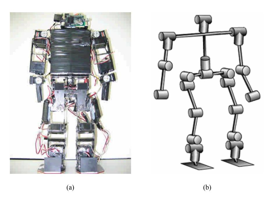
The photograph of the implemented biped robot is shown in Fig. 1(a), where servomotors with high torque are used as the actuators. The joints configuration of this robot is described in Fig. 1(b), where 24 degrees of freedom are implemented in the robot. There are 12 degrees of freedom on the two legs, and 2 degree of freedom on the neck, 8 degrees of freedom on the arm, and 2 degrees of freedom on the hip. In order to realize the normal walking motion of human, six degrees of freedom are adopted to implement the joints of one leg. In the neck of this robot, two degree of freedom is adopted so that the head of the robot can turn right-and-left and up-anddown.
Electronic Design
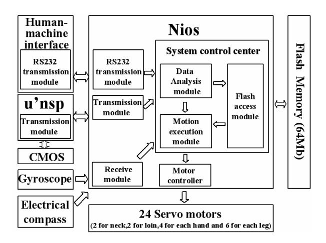
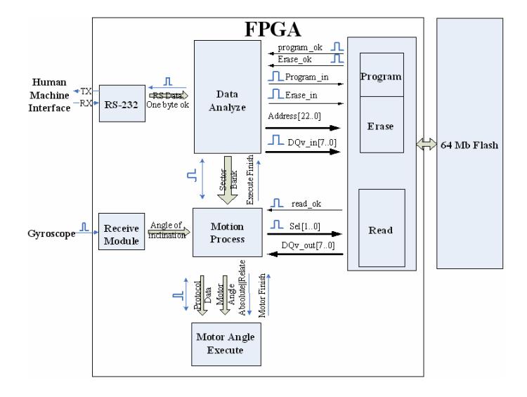
In the electronic design of the robot, the system block diagram is described in Fig.2, where 24 servomotors with high torque are used as the actuators of the robot. In order to build a fully autonomous vision-based humanoid robot, a 16-bit DSP processor with a CMOS sensor is chosen to process the vision image of environment. The image of the field is captured by the CMOS sensor and the position information of the ball and goals is processed and extracted by the DSP processor. Two IR sensors and a digital compass are installed on the body of robot to detect obstacles and determine the head direction of the robot respectively. In order to reduce the weight of robot, the concept of SOC design is applied in the complexity design of biped robot. The configuration of the FPGA chip is described Fig.3. The implemented FPGA chip can process the data obtained by IR sensors and the digital compass and generate desired pulses to control the angles of servomotors. Many functions are implemented on a FPGA chip to process the data and control the robot so that the weight of the robot is reduced.
In the electronic design of the robot, the main electronic components are a flash memory, a CMOS sensor, two gyroscopes, and a digital compass. They are described as follows:
Flash Memory
For the flexible reason, a flash memory is chosen to store the database of the motion of the robot. In this way, the user can adjustthemotorangleofrobot'smotion such as the motion of walk or turn on the PC via the human-machine interface. Then these motion data is saved on the flash memory so that the FPGA chip will read the motion data from the flash memory whentheDSPdecidestherobot'smotion.
CMOS Sensor
The CMOS sensor is installed in the head of the robot so that the vision of the field can be obtained. Two main parts are in the vision system of the robot: a CMOS sensor and a 16-bit DSP processor. The captured image data by the CMOS sensor is transmitted to the DSP processor via a serial port. Based on the given color and size of the object, the DSP processor can process the captured image data to determine the position of the object in this image. The noise of the environmental image can be eliminated by the DSP processor. Based on the extracted position information, an appropriate strategy is made and transmitted to the FPGA chip via a serial port.
Gyroscope
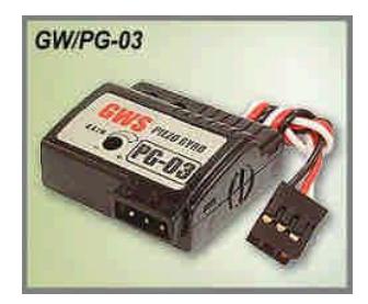
The gyroscope is installed to detect the inclinable angle of the robot. As shown in Fig. 4, PG-03 mode manufactured by GWS is used and its signal is received by NIOS to determine the inclinable angle. Then the robot can correct its actions by itself.
Digital Compass
In order to let the robot can avoid obstacles smoothly and go to the appointed place accurately, a digital compass is installed on the body of robot to determine the head direction of the robot. It provides the important direction information for the robot navigation. The digital compass can offer the indispensable magnetism information while navigating the robot. The digital compass picks the angle of the robot and the north geomagnetic pole. Its photograph and structure are respectively shown in Fig. 5 and Fig. 6. The pin name and function is shown in Table 1. The data of the digital compass is transmitted in the RS-232 mode and 4800 bps. Follow the chronological chart of the digital compass and offers a control signal to the model, as shown in Fig.7Fig. 7. We can get three materials that each one has 8 bits:Status、MSB and LSB . The first one is the state data. The others are the angle data. If the first one receive Hex-81, which shows the two angle data are not correct. If the first one receive Hex-80, which shows the two angle data are correct. We can get the clockwise angle of the robot to the North Pole of terrestrial magnetism according to Equation (1).
$$\theta = (\theta_{MSB} \times 256 + \theta_{LSB})/2 \tag{1}$$
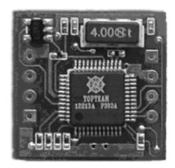
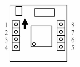
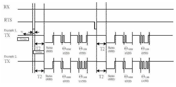
Table. 1. The pin name and function forms.
| Pin | Pin Name | Function |
|---|---|---|
| 1 | VCC | VCC |
| 2 | NC | Reserved |
| 3 | RTS | RS-232 Data Rx control |
| 4 | NC | Reserved |
| 5 | TX | RS-232 Data Tx |
| 6 | RXD | RS-232 Data Rx Control |
| 7 | GND | GND |
| 8 | NC | Reserved |
Human-Machine Interface
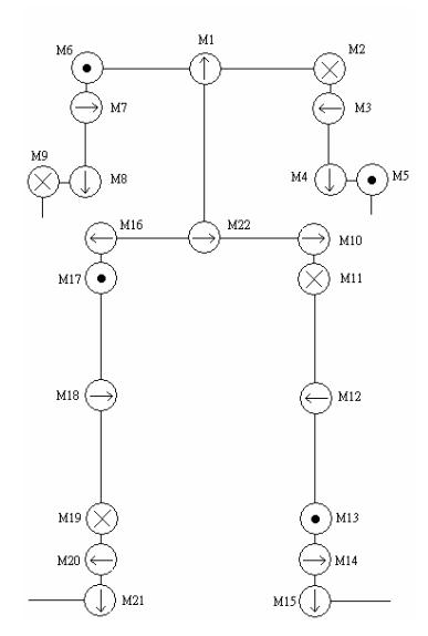
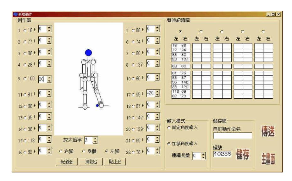
A human-machine window interface is designed and implemented by BCB to control and monitor the locomotion of the biped robot. This human-machine interface is designed to be a convenient develop platform to shorten the develop time of the locomotion control design. All of the robot statuses, environment variables, and the learning abilities can be adjusted and analyzed from this interface. Besides, the interface also provides a dynamic simulation. The joints of the robot for the simulation are shown in Fig. 8 and a window display of this interface is shown in Fig.9.
A protocol of the transmission is proposed to communicate between the BCB of the PC and the hardware circuit. There are two kinds of commands for the communication. The first one is the order command. The other one is the program command. The transmission type is a handshaking transmission. The PC transmits one byte to the FPGA chip, and then the FPGA chip transmits one byte to the PC. The transmitted data ispacketby"FE"and"FC".Ifthesecondofthetransmitted data is FD, The packet is the order command. Otherwise, the packet is the program command.
Order Command
The order command as shown in Table 2 ispicketedby"FD"and"FC".Thereare four kinds of order commands: erase chip, erase sector, execute, and autonomous. The first and second commands are used for erase the flash memory. The third command is used to execute the motion, such as walk and turn left. Each motion is stored in the different bank of different sector of the flash memory. Therefore, if the user wants to test the robot motion, the execution order will give the sector and bank data to the FPGA chip. Besides, the interface also provides an autonomous type. Once the FPGA chip receives an autonomous command, it will decide the robot motion automatically. The data format of order command is shown in Table 3.
Table 2. Communication protocol of the order command.
| 1 | 2 | 3 | 4 | 5 | 6 | 7 |
|---|---|---|---|---|---|---|
| FE | FD | Order | Order | Order | Order | FC |
Table 3. Data format and content of four order commands.
| Description | Order1 | Order2 | Order3 | Order4 |
|---|---|---|---|---|
| Erase Chip | F0 | 00 | 0043 | 00 |
| Erase sector | F0 | 01 | Sector | 01 |
| Execute | F1 | 00 | Sector | Bank |
| Autonomous | F1 0 | 01 | 014 | 01 |
Program Command
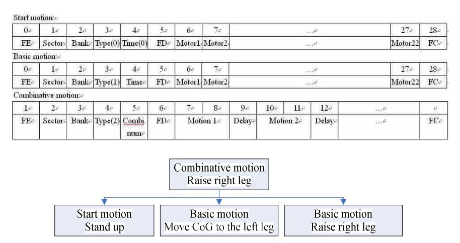
The program command is divided into three parts: start motion, basic motion, and combinative motion. The communication protocol is described in Table 4. The start motion is such as the motion of stand up. The basic motion is such as the motion of the center-of-gravity position to the right foot. These motions will be executed after start motion. The final one is the combinative motion. The combinative mode will integrate the start motion, basic motion and combinative motion. For example, if the combinative motion is raise the right leg. The whole motion can be illustrated as Fig. 10. In this case, stand up is the motion 1, move the center-of-gravity (CoG) position to the left foot is the motion 2, and raise the right leg is the motion 3.
Conclusions
In this paper, a design and implemented method of a humanoid soccer robot is proposed to kick the ball. A biped structure with 24 degrees of freedom is designed and implemented so that it can walk forward and backward, turn right and left, and kick the ball. A CMOS sensor, two gyroscopes, and a digital compass are integrated so that the robot can obtain the environmental information to decide the action behavior. A platform with a human-machine interface is implemented so that we can view the motion of the biped robot at any direction from the window interface. Based on the platform, we can simulate the motion of the robot so that the locomotion control design of the biped robot is fast and efficiency.
Acknowledgment
This research was supported in part by the National Science Council of the Republic of China under contract NSC 94-2213-E-032-002.
References
- Wong, C.C., Cheng, C.T., Wang, H.Y., Li, S.A., Huang, K.H., Wan, S.C., Yang, Y.T., Hsu, C.L., Wang, Y.T., Jhou, S.D., Chan, H.M., Huang, J.C., Hu, Y.Y.: Description of TKU-PaPaGo Team for Humanoid League of RoboCup 2005. RoboCup International Symposium 2005 (2005).
- Zhou, C., Jagannathan, K.: Adaptive Network Based Fuzzy of a Dynamic Biped Walking Control Robot. IEEE Int. Conf. on Robotics and Automation. 4 (2000) 3829-3834.
- Pauk, J. H., Chung, H.: ZMP Compensation by On-Line Trajectory Generation for Biped Robots. IEEE International Conference on Systems, Man, and Cybernetics. 4 (1999) 960-965.
- Huang, Q., Li, K., Nakamura, Y.: Humanoid Walk Control with Feedforward Dynamic Pattern and Feedback Sensory Reflection. IEEE International Symposium on Computational intelligence in Robotics and Automation. (2001) 29-34.
- Sugihara, T., Nakamura, Y., Inoue, H.: Real time Humanoid Motion Generation through ZMP Manipulation based on Inverted Pendulum Control. IEEE International Conference on Robotics and Automation. 2 (2002) 1404-1409.
- Furuta, T.: Design and Construction of a Series of Compact Humanoid Robots and Development of Biped Walk Control Strategies. IEEE International Conference on Robotics and Autonomous Systems. (2001) 65-88.
- Vukobratovic, M., Frank, A. A., Juricic, D.: On the Stability of Biped Locomotion. IEEE Trans. Bio-Med. Eng. 17 (1970) 25-36.
- Golliday, C. L., Jr., Hemami, H.: An Approach Analyzing Biped Locomotion Dynamics and Designing Robot Locomotion Control. IEEE Trans. Aut. Contr. (1977) 963-972.
- Miyazaki, F., Arimoto,S.: A Control Theoretic Study on Dynamical Biped Locomotion. ASME J. Dyna., Syst., Meas., Contr. 102 (1980) 233-239.
- Furusho, J., Masubuchi, M.: A Theoretically Motivated Reduced Order Model for the Control of Dynamic Biped Locomotion. ASME J. Dyna., Syst., Meas., Contr. 109 (1987) 155-163.