TeamOSAKA A (Kid size) Team Description Paper
Hitoshi Takayama, Reo Matsumura, Naoki Shibatani, Takuro Imagawa, Takeshi Maeda, Takahiro Miyashita, Tomotaka Takahashi, Yohei Akazawa, Nobuo Yamato, Hiroshi Ishiguro
Osaka Universities Intelligent Robotics Lab, 2-1 Yamada-oka Suita Osaka 565-0871 Japan; Vstone, 4-2-7 Shimaya Konohana-ku, Osaka, 554-0024, Japan; ATR Intelligent Robotics and Communications Lab, 2-2-2 Hikaridai Keihanna Science City, Kyoto, 619-0288, Japan; Robo Garage, Yoshidahonmachi Sakyo-ku, Kyoto, 606-8501, Japan; Systec Akazawa, 6-2-47 Noda Fukushima-ku, Osaka, 553-0005, Japan
http://www.ed.ams.eng.osaka-u.ac.jp/ · http://www.vstone.co.jp · http://www.irc.atr.jp/index.html · http://www.robo-garage.com/ · http://www.akazawa.co.jp · http://www.vstone.co.jp/top/products/robot/roboviemaker.html
Abstract This paper describes the specifications and the functions of the humanoid robot that TeamOSAKA have developed for RoboCup2006. This robot has 25 DOF as well as omni-directional image sensor, 2-axis acceleration sensors that detect gravity and 3-axis gyro sensors that detect angular velocity. This robot is developed as the platform of RoboCup Humanoid League and for the research of Coordination among robots, Teleportation by human operator, and robotic systems integrated with sensor networks.
1 Introduction
The robot that TeamOSAKA has developed for RoboCup 2006 is a fully autonomous humanoid robot. TeamOSAKA was established in 2003 to develop robot technologies in Osaka; actually, TeamOSAKA won RoboCup2004 in Lisbon and RoboCup 2005 in Osaka. Companies, universities, and cities are collaborating in TeamOSAKA whose members are Osaka City, Vstone Co. Ltd., Osaka University Intelligent Robotics Lab, Systec Akazawa, Robo Garage, and ATR Intelligent Robotics and Communications Lab. The rest of the paper contains the summarized description of each component of the robot. Mechanical specifications, electrical specifications, and software specifications are described in section 2, 3, and 4.
1.1 General specifications of the robot
Table 1 shows the general specifications of the robot. The significant features are as follows:
- A fully autonomous robot based on sensory information
- Wireless communication between robots
- Distributed system
Robots need to share the local information in order to recognize the relation of the partner robots and environment more exactly during the task such as 2on2 soccer game. Therefore, this robot communicates with each other by wireless network function. Moreover, distributed system enables us to maintain the robot more easily.
Table 1. General specifications of the robot
| Height [mm] | 480 |
|---|---|
| Width [mm] | 200 |
| Height [mm] | 150 |
| Weight [kg] | 3.2 |
2 Mechanical Specifications
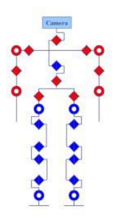
The robot has total of 25 DOF. Table 2 and Fig. 1 show the arrangement and types of the actuators. Table 3 shows the specifications of the actuators used for the robot. The actuator has a microcontroller and communicates with the host controller though UART multi drop network. Therefore the host controller can receive current angular position of each joint, speed, temperature, and calibrate pid gain and compliance parameter.
Normally, knee joint needs twice speed than the other leg joints in order to keep the same posture, for example when bend and stretch. Therefore, the robot possesses two actuators in the knee and the knee joint can move twice faster than the other joints.
Table 2 Motor types and rotation axis
| Part | Rotation Axis | Actuator |
|---|---|---|
| Head | Pitch | VstoneServoS |
| Body | Pitch, Yaw | VstoneServoM, VstoneServoS |
| Sholders | Roll, Pitch | VstoneServoS, VstoneServoS |
| Arms | Pitch, Yaw | VstoneServoS, VstoneServoS |
| Hips | Roll, Pitch, Yaw | VstoneServoM, VstoneServoM, VstoneServoS |
| Knees | Pitch, Pitch | VstoneServoM, VstoneServoM |
| Ankles | Roll, Pitch | VstoneServoM, VstoneServoM |
| Total DOF | 25 |
Table 3 Specifications of actuators
| Type | VstoneServoM | VstoneServoS |
|---|---|---|
| Size [mm x mm x mm] | 32.7 x 21 x 40.5 | 26 x 15 x 33 |
| Torque [kg cm] | 28.5 | 7.1 |
| Speed [sec / 60deg] | 0.14 | 0.11 |
| Weight [g] | 66 | 30 |
| Voltage Range [V] | 4 ~ 10 | 4 ~ 10 |
| Current Max [A] | 5 | 3 |
| Communication Speed [bps] | 1Mbps | 1Mbps |
| Microcontroller | R8C/Tiny 20MHz | R8C/Tiny 20MHz |
3 Electrical specifications
(Section content continues below in subsections)
3.1 Controllers
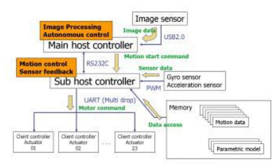
The robot has two host controllers and actuator controllers that are loaded in each actuator. One of the host controllers possesses image data from the image sensor and controls autonomous behavior of the robot (Main controller), and the other one computes the motion trajectory and sensor feedback values (Sub controller). Moreover actuator controller computes pid-control and drives the motor. Table 4 shows the specifications of these controllers.
3.2 Sensors
The robot has 5 types of sensors.
- Image sensor
This sensor captures environment image data around the robot. This sensor is controlled by main controller.
- Acceleration sensor
This sensor detects gravity vector when the robot is static. There are two applications with the sensor. One is recognizing whether it is standing or lying down and the robot gets up automatically. And the other is keeping the vertical posture on the level. This sensor is controlled by sub controller.
- Gyro sensor
This sensor detects angular velocity of the robot. The application of the sensor is keeping the posture of the robot on the level when the robot is moving. This sensor is controlled by sub controller.
- Potentiometer
This sensor detects the rotation angle of the actuator. With this sensor, the robot recognizes the current angular position of the joint. This sensor is controlled by actuator controller.
- Temperature sensor
This sensor detects the temperature of the actuator. If the temperature is high, the robot stops the movement and prevents the breakdown of the actuator. This sensor is controlled by actuator controller.
Table 4 Specifications of host and client controllers
| Main Controller | Sub Controller | Actuator Controller | |
|---|---|---|---|
| CPU | GeodeLX 800 | SH2 7054 | R8C/15Tiny |
| ROM | 4GB | 384 + 64 KB | 16 KB |
| RAM | 512 MB | 16 + 512 KB, 1 KB | |
| OS | Windows XP | None, None | |
| Interface | Storage device slot (CF card) x 1 | UART x 2 | UART x 1 |
| USB2.0 x 4 | 10bit AD converter x 8 | 10bit AD converter x 2 | |
| UART (RS232C) x 4 | GPIO | ||
| Analog video capture device x 2 | Input capture | ||
| Wireless network device IEEE802.11a x 1 | |||
| RGB display output interface x 1 | |||
| Speaker (1W) x 2 | |||
| Mic x 1 | |||
| Sensor | Image sensor x 1 | Acceleration sensor x 2 | Potentiometer |
| Gyro sensor x 3 | Temperature sensor | ||
| Application | Autonomous processing | Computing motion | Motor control |
| Image processing | Sensor feedback |
4 Software specifications
The software of the robot consists of several modules. Fig. 2 shows the overall system of the software.
4.1 Motion control module
The movement of the robot is implemented in two ways: real-time trajectory computation with inverse kinematics and predefined motion pattern.
- Real-time trajectory computation
When the goal position changes, the robot must normally stop walking and then start to walk to the new goal. However, this method wastes the time when the robot stops and walks again. In order to decrease the time, the robot computes it own walking trajectory real-time and computes the trajectory again when the new goal position is given.
- Predefined motion pattern
The method to make motion such as shooting the ball and waving hands depends on the feeling of the human heavily. Therefore we use "Robovie Maker" to make these motions, which enables us to make motion intuitively. The further information about "Robovie-Maker" is updated as follows (in Japanese):
http://www.vstone.co.jp/top/products/robot/roboviemaker.html
4.2 Sensor feedback module
Sub host controller recognizes and calibrates the posture of the robot with the acceleration sensors and gyro sensors.
- Acceleration sensor (Static stability) Acceleration sensor detects the gravity vector when robot is static. Therefore the robot can keep the vertical posture against the ground. With its feedback, the robot can walk through rough terrain in RoboCup 2005.
- Gyro sensors (Dynamic stability) When the robot is moving fast, the noise by the force of inertia is added to the signal of the acceleration sensor and it causes the decrease of the acceleration sensor's reliability. In order to keep the stability when the robot is moving; the robot detects the angular speed with gyro sensors and keeps dynamic stability.
4.3 Image processing module
The image processing algorithm is as follows:
- Capture images to transmit to main host controller.
- Beforehand, a human operator makes a color index table to recognize the target object. This color mapping method is RGB direct mapping method.
- Match the image data with the color index.
- Make the histogram with the specified color index (polar coordinate).
- Compute the median point of the target region by selecting the maximum peek in the histogram.
5 Conclusion
In this paper, we present the specifications of our robot that has two controllers and 25's DOF, and several kinds of sensors to autonomously generate various motions no only for RoboCup but also for several research issues.