Toin Phoenix Team Description Paper
Toin Phoenix Team
Abstract This paper describes kids size humanoid robot system of the team Toin Phoenix. Last year we developed kids size robots for Robocup 2005. The robots have following abilities: scan environment using laser range scanner to detect the ball and other objects, walk to any direction using hand crafted sequence of poses, and approach and kick the ball using deterministic maneuver. Major changes and improvements have been made for Robocup 2006 in aspects of both hardware and software, including mechanisms, locomotion, sensor systems, and higher level of software.
Introduction
This paper describes kids size humanoid robot system of the team Toin Phoenix. Last year we developed kids size robots for Robocup 2005. The robots has following abilities.
- Scans environment using laser range scanner to detect the ball and other objects.
- Walks to any direction using hand crafted sequence of poses.
- Approaches and kicks the ball using deterministic maneuver.
There are many limitation and problems with them. The first is lack of accuracy and robustness of its motions. The second is absence of tactical/strategical planner. And also, laser range scanners are prohibited in Robocup 2006.
We have redesigned our robot systems in aspects of both hardware and software for Robocup 2006. Major changes are, mechanisms, locomotion, sensor systems and higher level of softwares.
Actuator and Sensor System
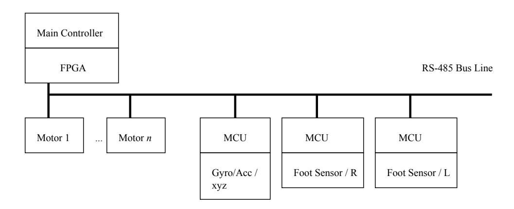
In this project, distributed control system is used. All motors and sensors are on RS-485 bus with host controller on main robot CPU. The bus is half-duplex, so all the transactions including status reading is initiated by the host. Because all the transactions are initiated by the host, there is no arbitration on the bus. It guarantees some real-timeness.
Sensors deployed in this project are as follows:
- MEMS gyroscope
- MEMS accelerometer
- FSR (Force Sensitive Resistor)
Gyroscopes and accelerometers are usually used in pairs to measure and stabilize upper body movement. They are used in pairs to complement their effective range of measurement in frequency space. Four FSR's are used in one sole to measure ZMP position.
Details on sensor feedback is described in following section.
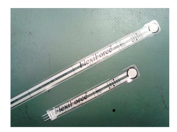
Brief spec of FlexiForce(FSR)
| Outside diameter size | Width 14mm, Length 205mm |
|---|---|
| The maximum measurement load 10 [N] | |
| Resistance at no load | 10 [MΩ] |
| Resistance at the maximum load 20 [kΩ] |
Mechanisms
Foot design FSR (Force Sensing Register) is used for four corners in foot back as a method of detecting ZMP. Four FSR is used for one foot, and eight FSR in total is used. Figure 2 is the FSR we use and table 1 is its brief specification.
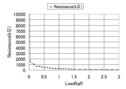
A FSR is a kind of variable resistance which value changes depending on load to act on. So, it can be used as a force sensor in a perpendicular direction. Figure. 3 shows the relation between load and resistance of FSR. Fig.3 shows the experiment method. The thin tubular rubber is placed on FSR and the load container is placed on them as shown in Fig.3. The load is applied to FSR adjusting amount of water in the container.
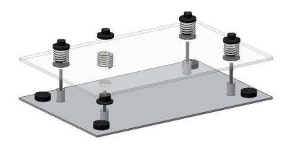
When small load is applied, resistance becomes very large value. It makes the resulting force value inaccurate. Therefore, it is necessary to put some load to offset measurable range. Figure.4 shows the structure of the foot. 4 springs are used to apply constant load on FSRs. Upper plate is attached to leg of the robot and FSRs between two plates are pressed by the robot and springs.
Software System
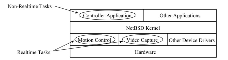
On main processor unit on the robot, there runs NetBSD as an operating system. Control software is written as applications and device drivers running on NetBSD.
Original NetBSD is multi-user preemptive operating system. User level application does not have privilege of preempting the BSD kernel, it lacks the real-timeness for usage such as motion control. In this project, real time tasks are written as device drivers
In NetBSD, user space application cannot preempt kernel task. Therefore it is necessary to write such a task in a device driver as an interrupt handler and use hardware timer to issue timer interrupt.
In this project, video capturing and motion control are coded as device drivers to ensure real-timeness.
Soft real time tasks such as decision making and image recognition are coded as user space application. These tasks communicate with real time tasks through ring buffers to absorb fluctuation of data rate on user space application.
Motion Generation
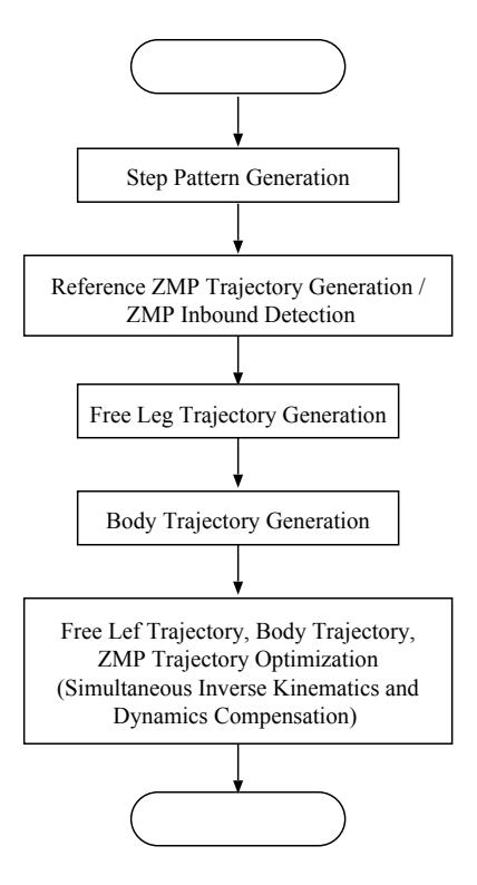
For application such as soccer, quick and fast movements are required and therefore maintaining dynamic stability becomes important. For this reason, ZMP was used to evaluate the stability. Simultaneous optimization was performed to generate joint trajectory that satisfies free leg trajectory, body trajectory, and ZMP trajectory at same time. Newton-Raphson method was used in optimization.
Newton-Euler formulation was used to calculate the inverse dynamics of the robot and ZMP. By calculating inverse dynamics, joint torque can be calculated, that can be used to determine if the generated movements can be realized by the motors attached on the robot.
Figure 6 depicts calculation flow of motion generation with ZMP compensation.
ZMP referencing is also used for movements such as kicking a ball. In this case, ZMP is kept in area near center of the sole. By considering ZMP in these movements, robot can produce faster and stronger kick without losing the stability.
Gait Planning
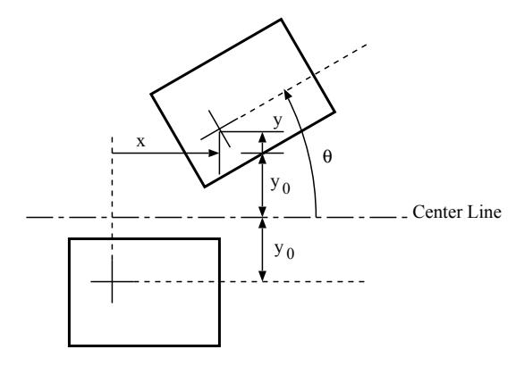
To achieve arbitrary direction walking, movements are partitioned into fragments. State of walking can be described as a point in multi-dimensional space. For an example, walking on flat surface can be expressed as three-dimensional space of x, y, and θ (See Figure 7).
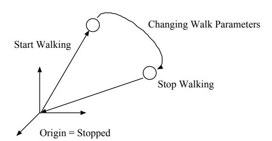
There are three intuitive phases of walking: start up, constant, and stopping. According to the model shown above, These phases can be described as follows. Start up phase is walking with state transition from origin to some value. Constant phase is walking with state kept at same point. Stopping phase is walking with state transition from some point to origin (See Figure 8). Extending this concept, various state transition can be defined.
In this project, fragments of movements toward all direction and combination will be precalculated. All transitions between the states will also be precalculated. With this model, arbitrary walking can be achieved by selecting appropriate states and transitions with latency of maximum two steps. This technique is effective on using ZMP reference walking because it is inherently impossible to generate gait truly on-line with ZMP reference walking since it involves recursive calculation for optimization.
For movements to fine adjust robot position, which will be used for adjusting position of the robot against the ball, step width is interpolated between precalculated values. Strictly speaking, generated gait will not follow the designed ZMP trajectory, but the gait will be robust enough because the inbound judgment of ZMP is done with smaller polygon than actual sole.
Feedback System
The described method will generate stable movement if there is no disturbance. However, in reality, there are not only disturbances from environment, but modeling error will also act as a disturbance. To stabilize robot even under disturbances, on-line feedback stabilization is necessary.
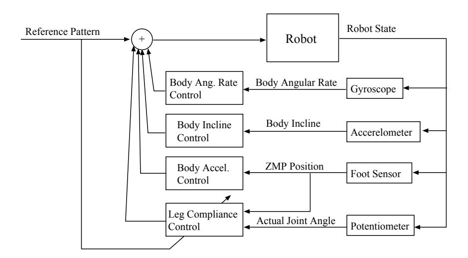
Following feedback loops are present to stabilize the robot.
- Body angular rate control
- Body incline control
- Body acceleration control (ZMP control)
- Leg compliance control
Figure 9 depicts conceptual block diagram of the feedback control system.
Body angular rate control and incline control will maintain body posture calculated in gait generation. Gyroscope and accelerometer are used respectively. Body acceleration control prevents ZMP to reach the edge of the supporting convex hull, which can result in falling down on the floor. Foot pressure sensors are used to measure ZMP.
Feedbacks above are used for suppressing the effect of disturbance, but the compliance control is used to suppress the cause of the disturbance. Two leg support of the walking forms closed kinematic chain which is kinematically redundant. It means presence of internal force is possible. If there is internal force stored in closed kinematic chain will be released when the friction between the floor and a foot becomes smaller than the internal force. This phenomenon can be observed as a "jump" of link movement. This kind of impulsive movement can be severe disturbance on feedback loops and can result in loss of stability. The internal force may be produced by mechanical misalignments and tracking error of the joint servo.
If the motor torque is large enough to lift the robot, redundant constraint may result in uneven contact between the robot and the floor. By reducing the stiffness of one leg in double support phase, both internal force and misalignment can be relieved.
Localization
Localization is done by dead reckoning which accumulates expected difference of position and direction from current motion state. However, positioning error is also accumulated into estimated position, it must be compensated by measuring relative position to some object in environment which position is fixed. Further more, this kind of objects are not always visible because of occlusion and limited camera sight.
We use a maximum likelihood estimation framework for positioning. The dead reckoning subsystem updates estimated position and estimated positioning error on regular basis. If the vision system detects a corner pole and goal together, it modifies estimated position and estimated positioning error using constraints.
The higher level of software, which manages strategy level of decision, monitors estimated positioning error. If it go too large, the strategy subsystem interrupts current tactics, and observes environment to correct its position.
Local navigation
The position and direction of the robot is effected by every state of motion(start up phase, some constant phase and stopping phase or transition phase of motion). In ordinary case, the effect of single motion(single step) is not large enough to approach target position and direction, hence combination of some motion to reach the goal should be calculated. In our system, GA is used to search and optimize the sequence of motion. The sequence is periodically re-evaluated and replaced on the fly during execution of it. Therefore if unexpected disturbance or moving obstacle can be handled.
Tactics and Strategy
Strategy and tactics are implemented as some kind of FSM. Tactical level of algorithms such as ball tracking or intercepting are one of states. State transition is controlled and triggered by strategy subsystem which monitors image processing subsystem and localization subsystem.
Conclusion
Major improvements against Robocup 2005 version of our robot system are described. We've got a powerful controller, reliable mechanism, precise vision system and well structured software. Our robots will show an advanced performance at Robocup 2006.