TeamSpirit Description Paper
Dae-jin Kim, Do-ryang Kim, Eu-myung Joo, Dong-hui Song, Je-yong Lee
Seoul National University of Technology Mechatronics Lab Room 231, Hitech Hall, Seoul National University of Technology, Gongneung 2(i)-dong, 139-743 Nowon-gu, Seoul, Republic of Korea; Robocube-tech, Room 101-A, Business Incubation Center, Seoul National University of Technology, Gongneung 2(i)-dong, 139-743 Nowon-gu, Seoul, Republic of Korea
http://cafe.daum.net/RnD.SNUT · http://www.robocube.co.kr · www.robotis.com
Abstract This paper describes the specifications of our humanoid soccer robots. We have developed this robot for Robocup2009. This robot has 18 DOF, 1-CMOS sensor(wide angle lens), 2-axis rate gyro sensors, 1-axis tilt sensor. This robot has fully autonomous system fitting the humanoid Robocup competition. We have researched stabilization and artificial intelligence of the humanoid robot. This robot is integrated our whole technique.
Introduction
TeamSpirit consists of the company which was called Robocube-tech and our humanoid laboratory. Our humanoid laboratory was established in Seoul National University of Technology, Korea to develop the human ability in robot. Team Spirit took part in Robocup2008 Suzhou which was the first participation in the Robocup. We advanced to the quarter final last year. A year later, our robots are upgraded continuously in parts. The rest of the paper contains the summarized description of each component of the robots but that may change prior to the competition.
Mechanical Specifications
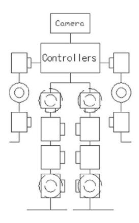
The robot has total of 18 DOF. Table 1 and Fig. 1 show the arrangement and types of the actuators. Table 2 shows the specifications of the actuators used for the robot. The actuator has a micro-controller and communicates with the sub controller though RS-485. Therefore the sub controller can check current angular position of each joint, torque, speed, temperature, and calibrate compliance parameter.
Table 1. Motor types and rotation axisFont sizes of headings.
| Part | Rotation Axis | Actuator |
|---|---|---|
| Shoulde | Pitch, Roll | (RX-28, RX-28) ×2 |
| rs | ||
| Arms | Pitch | (RX−28) ×2 |
| Hips | Roll, Pitch, | (RX-64, RX-64, RX-28) |
| Yaw | ×2 | |
| Knees | Roll, Pitch | RX-64 ×2 |
| Ankles | Total DOF | (RX-64, RX-64) ×2 |
| Total DOF | 18 |
Table 2. Specifications of Actuators
| Type | RX-28 | RX-64 |
|---|---|---|
| $\texttt{Size[mm} \times \texttt{mm} \times \texttt{mm]}$ | 35.6×50.6×35 .5 |
40.2×61.1×4 1 |
| Torque[kg cm] | 37.7(at 16V) | 64.4(at 15V) |
| Speed [sec / 60deg] | 0.126(at 16V) | 0.188(at 15V) |
| Weight[g] | 72 | 125 |
| Voltage[V] | 12~16 | 12~21 |
Electrical specifications
(see subsections)
Controllers
There are three controllers in upper body of robot.
One is a main controller that receives images from two USB cameras and reasons about situations and commands sub controller to next motion via RS-485.
Anther is a sub controller that receives motion commands and controls with transferring information about each angle of motors and transfers information about each sensor to main controller. Here is a specification of contollers at Table 3.
The other is a motor controller in Dynamixel servo motor. We mentioned above about mechanical part of the servo motor. In this section, we add electrical part of the servo motor at section 3.3 Electrical specification of Dynamixel.
Table 3. Specifications of Controllers
| Main Controller | Sub Controller | Motor Controller |
|
|---|---|---|---|
| CPU | Celeron-M 600 MHz |
TMS320F2810 | ATMEGA8 |
| ROM | 8GB | 512KB | 8KB |
| RAM | 1GB | 4KB | 1KB |
| Detail | Windows XP CF Card × 1 USB2.0 × 6 |
150MIPS UART(RS-232, RS- 485) 32-bit Timer × 4 |
16MPS UART(RS-485) 10-bit ADC × 6 |
| RGB Output × 1 | 12-bit ADC $\times$ 16 | 8-bit Timer $\times$ 2 | |
| UART (RS232) $\times$ 2 | 16-bit Timer × 1 |
Sensor
A Robot has 4 kinds of sensor. Tilt, 2-axis Rate gyro, 1-axis Accelometer and 1-Camera is placed in chest of robot. CMOS-Camera(wide angle lens) is placed on head of robot. Here is a description of sensor at Table 4.
Table 4. Description of Sensor
| Sensor | Place | Purpose |
|---|---|---|
| Tilt | Chest | Check status whether robot is standing or laying |
| Rate gyro | Chest | Make robot's walking more stable Compensate each joint with angle at memorized walking pattern |
| USB CMOS CAM |
Head | Recognize the objects and localization More wide FOV(wide angle lens) |
Electrical specification of Dynamixel
We can control motors more easy, because we use Dynamixel. There are only two things that we do for use this motor. Supplying power and connecting RS-485 serial communication are all. We descript features at Table 5.
Table 5. Features of Dynamixel
| Feature | Description | ||
|---|---|---|---|
| Temperature | Sensing of motor Operating stop at set value of temperature |
||
| 485 | Up to 1MBPS | ||
| Checking status |
Transferring current angle of joint, temperature, torque |
Software specifications
Our team's software structure is divided into 3 parts. First part's job is image processing and making commands that are transmitted the sub-controller(motion controller). Second part's job is that transmit the motion control data to each actuator controller and feedback the sensors data. Fig. 2 shows the software structure of our soccer robot.
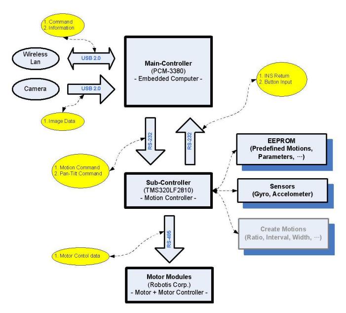
Image processing and making command
We use 1-CMOS camera that has 300,000 pixel resolutions. The purpose of using 1-camera is in order to recognize the localization of the objects and the robot. The camera and the main-controller communicate by USB 2.0. Result of the image processing, we acquire the information (Localization of the robot, distance and angle of the objects) . Finally base on the information the logic algorithm make a decision of the environment and transmit to sub-controller.
The image processing algorithm is as follows:
- Captured images to transmit to main-controller.
- RGB image format convert HSV format (because HSV is more robust than RGB).
- Operate the histogram back-projection. (Use color of the object)
- Convolution with kernel and make the probability distribution map.
- Find the object in map. (The most probability in probability distribution map is the
Motion control and sensor feedback
The sub-controller has 2 important tasks. The one is motion data transmission to motor-modules that have motor-controller and motor, potentiometer.(We use motor module of the ROBOTIS corporation – www.robotis.com) Because of uncertain condition, we make many motion data to good performance. The motions saved EEPROM execute by the command transmitted by main-controller. The other is sensors(Tilt sensor, Rate gyro sensor) feedback and use them to motion. The Tilt sensor detect pose of the robot. When the robot is fall down, output of the sensor is changed. The rate gyro sensor detects the angular velocity. When the robot is moving, use the rate gyro sensor detected the angular velocity for stabilization of the robot.
Conclusion
In this paper, we have presented the specification of the robot. Several parts of the robots have changed and upgraded. Since last year, our robots are now obtaining human sensibility like navigating obstacles. Also we have wide experience from Robocup2008 at Suzhou in China. We really look forward to playing in Robocup2009 in Graz.