Virbot@field : taking service robots to play soccer
Llarena Adalberto, Escalante Boris, Torres Luis, Abad Verónica, Vázquez Lauro
Bio-Robotics Laboratory, Department of Electrical Engineering Universidad Nacional Autónoma de México, UNAM
Abstract This paper describes the efforts to use the VirBot architecture for controlling the operation of robotic biped soccer players. The ViRbot architecture is designed to deal with a wide range of problems for the service robots, including navigating, motion planning, global localization, speech recognition and task planning using a rule based system. This paper discusses what modifications must be done when using devices with limited resources and how decisions can be taken.
1 Introduction
The ViRbot system [1] has been tested in the Robocup@Home [2] category in the Robocup competition at Bremen, Germany in 2006 with the robot TX8 and in the same competition in Atlanta, USA in 2007 with the robot TPR8, getting the 3rd place. In the humanoid category we have participated in the Mexican Robotics Open 2007 with a demonstration of our system.
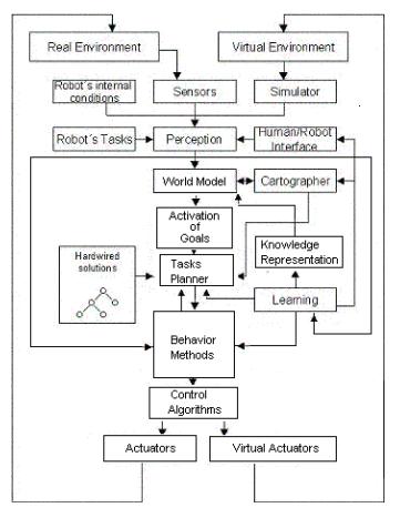
The ViRbot system divides the operation of a mobile robot in several subsystems:
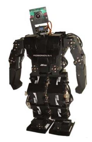
Each subsystem has a specific function that contributes to the final operation of the robot. When trying to control an autonomous biped robot such as Robonova I [3] with limited processing capabilities, several adaptations must be done to the architecture in order to simplify the complexity of operation, localization and knowledge representation, see figure 2.
This paper discusses how the VirBot modules can be modified to allow biped robots to play soccer.
2 Module Description
This section explains the different ViRbot modules and how they can be modified.
2.1 Internal Sensors
In the case of our biped robots, basically the internal sensors are a gyroscope and tilt sensors, digital compass and Triple Axis Acelerometer. They serve to control the balance of the robot and detect fallings. The biggest difference in biped robots is that there are no wheels and wheel encoders, so the localization problem becomes more difficult to address.
2.2 External Sensors
The only external sensor currently used in our robots is a CMU Cam 3 camera [4], since there are imposed restrictions when using sonar and IR sensors. This camera is equipped with a Philips LPC2106 processor, 64 Kb RAM, 128 Kb ROM, serial port and SD card slot. It can grab RGB and YCrCb images up to 352 by 288 pixels at rates of 26 FPS. We do not use any other contact, reflective, infrared or microphone sensor. For this reason the amount of information the robot can extract from the environment is limited to visual information.
2.3 Human-Robot Interface
As mentioned above, due to space and processing limitations in small biped robots, currently they are not equipped with microphones and speech recognition. In the future some speech recognition in Digital Signal Processors DSP's will be implemented.
2.4 Robot Control Module
Like the TX8 and TParacho robots, our robots are equipped with on-board controlling card. In this case a Micom MR-C3000 with an ATmega 128 MPU with 32K flash memory. All the movements the robot does, like walking or kicking, are programmed as single routines in the Robonova I board, using RoboBasic [5]. Once the program is downloaded and stored in the robot, the commands are fired through the robot's standard RS-232 serial port connected directly to the CMUCam 3 serial port (our controlling device). The internal sensors are directly attached to the robot's board, so it uses their reading to correct position and standing-up the robot when falling down.
2.5 Perception Module
Unlike the service robots, the visual processing and robot's intelligence is done in the same board, in this case the CMUCam 3. Despite we have recently migrated successfully entirely our ViRbot system to the Pocket PC architecture, our tests on the robot demonstrated it is still too heavy to be carried out for the Robonova. We are currently using basic YCrCb [6] color segmentation on the camera to find the ball, enemies and goal areas.
2.6 Global Localization Module
Since there is no map representation and the environment is always changing, due to the self, others and ball movements, a vision based localization method is necessary. Currently MCL Monte Carlo Localization [7] is being implemented but it becomes more inaccurate because there are no map, laser and sonar readings, and the only fixed characteristics are the field lines, goal areas and two landmark poles. By the moment our localizing algorithm uses the goal areas color and the amount of viewable pixels of such color to determine its distance and current orientation. The movement estimation is obtained by previously measuring the movements the robot does after each command and getting its probability density. When turning, for example, each turn has a fixed amount and successive turns are accumulated. The same applies for walking and running. Obviously a good robot calibration becomes fundamental.
2.7 Cartographer
Since the only elements in the field are the robots and the ball, and the field is a fixedsize rectangle, the map consists on a probabilistic occupancy grid. The field is divided into regions of 5 per 5 centimeters. One byte per location indicates the probability (from zero to +-128) of being occupied and the sign indicates if it is a partner or enemy robot. In total 5,400 bytes are needed for storing the assumptions about all the elements in the field, except the ball and the self position, those are carried separately. Since the CMUCam 3 incorporates a SD connector, currently is possible to decide where to store the information. By now the map is stored in a 1 GB SD secondary memory card.
2.8 Movement Planner
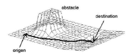
The map representation allows calculating the robot movements in a straightforward way. As implemented in the service robot, here the robot uses Potential Fields Theory [8]. Under this idea, the robot is considered as a particle under the influence of an artificial potential field ∇U whose local variations reflects the free space structure and it depends on the obstacles and the goal point that the robot needs to reach. The potential field function is defined as the sum of an attraction field that push the robot to the goal (the ball in this case) and a repulsive field that take it away from the obstacles (other robots). The probabilistic occupancy grid representation gives directly a good approximation to the force field:
The movement planning is done by iterations, in which and artificial attracting force is induced by the ball and repulsive forces are induced by the enemy robots. The sum of those forces will be the final direction the robot will follow, in the form of steps and turns.
2.8 Knowledge Representation
Unlike the ViRbot service robots, CLIPS Expert System [9] cannot be longer used to represent rules and to fire actions in these limited robots, and another way of managing actions must be used. Commonly, variable ranges are used to decide the robot actions, in the form of:
 if var1 > lower_val1 and var1 < upper_val1 and
var2 > lower_val2 and var2 < upper_val2 and
…
varN > lower_valN and varN < upper_valN then
robot.action();
else
if …
Example of a Computer Program for performing actions based on data ranges
but when having many variables becomes difficult to establish such ranges in order to avoid letting some ranges out of decisions or, in the opposite case, giving some ranges more than one action. Also the priority management becomes difficult to modify. This is known as the Subsumption Model [10] and it's used in ViRbot as the Arbiter.
In this case, we are implementing a Fuzzy Rule Decision System [11]. A fuzzy system consist of a number of Fuzzy Rules in the form of
$$R^{(l)}: IF \ x_1 \ is \ F_1^l \ and \cdots and \ x_n \ is \ F_n^l \ THEN \ y_1^l \ is \ G_1^l, \cdots, y_m^l \ is \ G_m^l$$
This is known as pure fuzzy form, where $F_1^l, \dots, F_n^l$ represent fuzzy values of each variable and the output function $G^l$ is also a fuzzy variable. In this case we have a MIMO (Multiple Input Multiple Output) fuzzy rule system. We use this kind of system to activate the different behaviors like kick or step. For instance one fuzzy rule can be:
R: If ball distance is near and kicking direction is good then kick is good
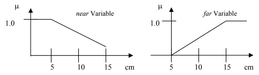
When fuzzifying one variable, it's possible to give a natural meaning to a value (or range of values) of a given variable. By natural we mean linguistic understandable meaning. For example we can define the terms near and far for the ball_distance variable as follows:
2.9 Behavior Selection
When evaluating a fuzzy rule, the fuzzy value $\mu$ is evaluated for every fuzzy variable and the rule's final $\mu$ is calculated using fuzzy inference (in our case a simple product). Once all fuzzy rules have been evaluated, all the results are combined using a defuzzifier for obtaining the final output (in our case we use the maximum $\mu$ to fire the behavior $\mu$ ). As seen above, this way of computing outputs is very similar to defining ranges, but outputs are basically combined and then the action with the biggest output value is selected. This method allows easy error detection and bad activation values. Also, fuzzy rules can be stored on secondary memory in order to be transferred to other robots only adjusting their belonging factors ( $\mu$ functions), and more new rules can be added with a well established method for combining them.
2.10 Learning Module
Currently no learning is implemented in our robots.
2.11 Future Works
We are intending to develop a goal-area detection by form to agree with the Robocup regulations for future competitions and self-calibrated vision and control algorithms are currently being developed by our new members.
3 Conclusions and Discussion
This paper proposes some basic modifications to the ViRbot architecture, allowing biped robots to play soccer. Also proposes a way of representing and managing knowledge and easily computing behavior responses with visual sensors.
In the past edition of Robocup in Suzhou China, we reached the quarter-finals of the event, being the best team in America in our first participation. We detected some problems with the localization and specifically with the ankle movement when turning. We have re-designed our robots based on the Robonova-I design but adding 6 DOF more to be able to rotate the whole leg around the hip articulation, and a 360 degrees arm rotation by the shoulders to be able to do the throw-in challenge.
By now the biggest challenge will be communicating the robots with wi-fi technology to become more collaborative and achieve more team coordination. Also the vision calibration will be fundamental for getting a better place in the competition. We have to demonstrate why we did arrive to finals last year.
References
- Jesús Savage, Adalberto LLarena, Gerardo Carrera, Sergio Cuellar, David Esparza, Yukihiro Minami, Ulises Peñuelas; ViRbot: A System for the Operation of Mobile Robots. RoboCup 2007 Symposium, Atlanta, EU, 2007
- Robocup@Home, http://www.ai.rug.nl/robocupathome/, 2006
- http://www.robonova.de/
- http://seattlerobotics.com/
- http://www.robobasic.com/
- http://en.wikipedia.org/wiki/YCbCr
- Thrun S., Montemerlo M.., Koller D., Wegbreit B., FastSLAM: An Efficient Solution to the Simultaneous Localization And Mapping Problem with Unknown Data Association, Proceedings of the IEEE Int. Conference on Robotics and Automation (ICRA), 2003
- Latombe, J.C. Robot Motion Planning. Massachusetts, USA: Kluwer Academic Publishers, 1991
- CLIPS Reference Manual Version 6.0. Technical Report Number JSC-25012. Software Technology Branch, Lyndon B. Johnson Space Center, Houston, TX, 1994
- Muller J.P. and M.Pischeli, and M. Thiel. Modeling reactive behavior in vertically layered agent architectures Intelligent Agents - Theories, Architectures, and Languages, volume 890 of Lecture Notes in AI. Springer, January 1995
- Conner, D. Fuzzy Logic Control System. EDN, pp. 77-88, 1993
- Takagi, T. and Sugeno, M., "Fuzzy identification of systems and its application to modeling and control," IEEE Trans. Systems Man Cybernet. 15 (1985) 116-132
- Haykin, S. Neural Networks. A Comprehensive Foundation, 2nd Edition, Prentice Hall 1999