Team DARwIn
Jaekweon Han, Robert Nguyen, Stephen McGill, Dinesh Thakur, Dennis Hong, Dan Lee
RoMeLa, Department of Mechanical Engineering, Virginia Tech, USA; GRASP Lab, School of Engineering and Applied Science, University of Pennsylvania, USA
www.romela.org/robocup · http://fling.seas.upenn.edu/˜robocup/
Abstract This paper details the hardware, software, and electrical design of the humanoid robot family, DARwIn (Dynamic Anthropomorphic Robot with Intelligence)–a robot family designed as a platform for researching bipedal motions. The DARwIn family was the first US entry into the humanoid division of RoboCup.
1 Introduction
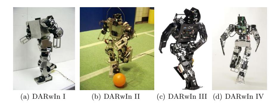
The DARwIn (Dynamic Anthropomorphic Robot with Intelligence) series robot is a family of humanoid robots capable of bipedal walking and performing human-like motions (Fig. 1). DARwIn is a research platform developed at the Robotics and Mechanisms Laboratory (RoMeLa) at Virginia Tech for studying robot locomotion and sensing. It was also utilized as the base platform for Virginia Tech's first entry to the humanoid division of RoboCup 2007. [1, 2]. The 560 mm tall, 3.6 kg robot (the latest version of DARwIn) has 20 degrees-of-freedom (DOF) with each joint actuated by coreless DC motors via distributed control with controllable compliance. Using a computer vision system and accelerometer, DARwIn can implement human-like gaits while navigating obstacles and traverse uneven terrain while implementing complex behaviors such as playing soccer.
For RoboCup 2010, Team VT DARwIn from the Humanoid League and UPennalizers from the Standard Platform League are teaming up together to form Team DARwIn in the Humanoid League. With Virginia Tech's expertise in mechanical design and University of Pennsylvania's expertise in software engineering and strategy, we hope to develop a a formidable opponent to compete in RoboCup.
2 Research
The DARwIn family serves as a research platform used for studying dynamic gaits and walking control algorithms. With few exceptions (i.e. the Honda ASIMO, the Sony QRIO, and the KAIST HUBO [3–7]), most legged robots today walk using what is called the static stability criterion. The static stability criterion is an approach to prevent the robot from falling down by keeping the center of mass of its body over the support polygon by adjusting the position of its links and pose of its body very slowly to minimize dynamic effects [5]. Thus at any given instant in the walk, the robot could "pause" and not fall over. Static stability walking is generally energy inefficient since the robot must constantly adjust its pose to keep the center of mass of the robot over its support polygon, which generally requires large torques at the joint actuators (similar to a human standing still with one foot off the ground). Humans naturally walk dynamically with the center of mass rarely inside the support polygon. Thus human walking can be considered as a cycle of continuously falling and catching its fall: a cycle of exchanging potential energy and kinetic energy of the system like the motion of an inverted pendulum. Humans fall forward and catch themselves with the swinging foot while continuously progressing forward. This falling motion allows the center of mass to continually move forward, minimizing the energy that would reduce the momentum. The lowered potential energy from this forward motion is then increased again by the lifting motion of the supporting leg.
One natural question that arises when examining dynamic walking is how to classify the stability of the gait. Dynamic stability is commonly measured using the Zero Moment Point (ZMP), which is defined as the point where the influence of all forces acting on the mechanism can be replaced by one single force without a moment term [8]. If this point remains in the support polygon, then the robot can have some control over the motion of itself by applying force and/or torque to the ground. Once the ZMP moves to the edge of the foot, the robot is on the verge of stability and can do nothing to recover without extending the support polygon (planting another foot or arm). Parameterized gaits can be optimized using the ZMP as a stability criterion or stable hyperbolic gaits can be generated by solving the ZMP equation for a path of the center of mass. Additionally, the ZMP can be measured directly or estimated during walking to give the robot feedback to correct and control its walking. DARwIn is developed and being used for research on such dynamic gaits and control strategies for stability [5, 9].
3 Hardware
DARwIn IV has 20 degrees of freedom (six in each leg, three in each arm, one in the waist, and one in the head). The robot's links are fabricated out of aluminum. The robot uses Robotis' Dynamixel EX-106, RX-64, and RX-28 motors for the joints [10]. The motors operate on a serial RS485 network, allowing the motors to be daisy chained together. Each motor has its own built-in potentiometer (with the exception of the EX-106 which has an optical encoder) and position feedback controller, creating distributed control. The computers, sensors, electronics, and computer ports are distributed about DARwIn's upper torso.
4 Electronics
DARwIn IV's electronic system provides power distribution, communication buses, computing platforms, and sensing schemes aimed at making sense of a salient environment. DARwIn's power is provided by two 8.2V (nominal) lithium polymer batteries wired in series providing a total of 16.4V to the joint actuators and electronics. These batteries provide 2.1 Ah, which gives DARwIn a little over 10 minutes of run time.
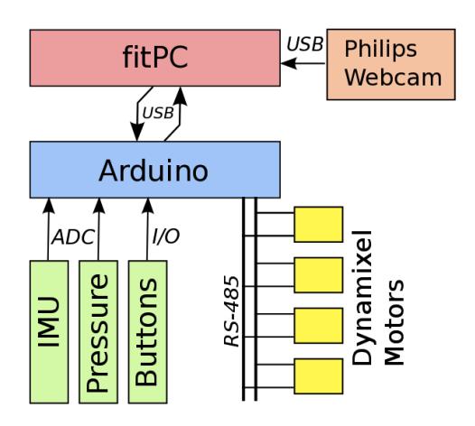
Computing tasks are performed on a Compulabs Fit-PC2 computing system that runs the Intel Atom Z530 CPU with 1GB of onboard RAM and built-in WiFi. The PC runs off the main battery supply, and consumes 8W at full CPU usage. In addition, the computer connects to both a Philips SPC1300 camera and an Arduino microcontroller board.
The Arduino board, featuring the ATmega1280, acts as the communication relay between the Dynamixel motors and the fitPC. The microcontroller also provides sensor acquisition and processing. Switches, a 6 degree of freedom Inertial Measurement Unit (IMU), and foot sensors will aid in correcting gait cycles in the face of perturbations. A block diagram that outlines the computing relationship is shown in Fig. 2.
5 Software
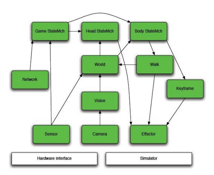
The software architecture for the robots is shown in Fig. 3. This architecture is novel in that it uses MATLAB as a common development platform. Since many of the students do not have strong programming backgrounds, this development platform allows them to participate more fully on the team. Low-level interfaces to the hardware level are implemented as compiled Mex routines callable from MATLAB. These routines provide access to the camera and the microcontroller which inturn communicates with the servos and the IMU, and allow the higherlevel routines to modify joint angles and stiffnesses.
Additionally, by changing a simple PATH variable, a set of simulated interfaces can be swapped in for onboard development and testing. This allows for easy debugging on logged data even without access to the robotics hardware. The MATLAB routines consist of a variety of modules, layered hierarchically:
- Sensor Module that is responsible for reading joint encoders, IMU, foot sensors, battery status, and button presses on the robot.
- Camera Interface to the video camera system, including setting parameters, switching cameras, and reading the raw YUYV images.
- Effector Module to set and vary motor joints and parameters, as well as body and face LED's.
- Vision Uses acquired camera images to deduce presence and relative location of the ball, goals, lines, and other robots.
- World Models world state of the robot, including pose and altered ball location.
- Game StateMch Game state machine to respond to Robocup game controller and referee button pushes.
- Head StateMch Head state machine to implement ball tracking, searching, and lookaround behaviors.
- Body StateMch Body state machine to switch between chasing, ball approach, dribbling, and kicking behaviors.
- Keyframe Keyframe motion generator used for scripted motions such as getup and kick motions.
- Walk Omnidirectional locomotion module.
In order to simplify development, all interprocess communications are performed by passing MATLAB structures between the various modules, as well as between robots. [11]
6 Vision
In each new setting, we may encounter different field conditions such as a change in lighting or the actual color hue of the field objects. In order to account for this, we log a series of images that are then used to train a lookup table . A MATLAB tool enables us to define the YCbCr values that correspond to green, yellow, white, etc. Once these specific values are selected and defined, the distribution of the points in the color space are spread out and generalized to account for a greater variation. This is done with a Gaussian mixture model that analyzes the probability density function of each of the previously defined pixel values. The boundaries of the color classes are then expanded according to Bayes Theorem. We can then process the individual pixels of the new images by matching their YCbCr values to the broadened definition of the values in the lookup table.
After the image is segmented into its corresponding color classes using the look-up table, the segmentation is bitwise OR-ed in 4x4 blocks. The initial object hypotheses for the ball and goal posts are found by finding connected components in the smaller, bit OR-ed, image, and then using the original image we calculated the statistics of each region. Processing the bit OR-ed image first allowed us to greatly speed up the computation of the system. The bit OR-ed image also produced the set of points that are used in our line detection algorithm.
We then check the segmented components for certain attributes like size, shape, and position in order to classify objects, such as the ball and the goal posts. We also compute statistics for the position of detected objects in the world coordinate system using the inverse kinematics of the robot, the centroid, and the bounding box to further filter the object hypotheses. Using these we are able to track the ball and identify the existence and size of goal posts and consequently localize our position on the field. [11]
7 Conclusion
Building on previous research and RoboCup experience, DARwIn IV represents the evolution of hardware and software. The combination of DARwIn's hardware, electronic, and software design from both Virginia Tech and University of Pennsylvania should prove to be very powerful and make DARwIn a formidable opponent at RoboCup while still maintaining its primary purpose as a research platform for studying robot humanoid motions.
References
- D. Hong. Biologically inspired locomotion strategies: Novel ground mobile robots at romela. 3rd International Conference on Ubiquitous Robots and Ambient Intelligence, Seoul, S. Korea, October 2006.
- K. Muecke and D. Hong. Darwin's evolution: Development of a humanoid robot. Proc. IEEE/RSJ Int. Conf. on Intelligent Robots and Systems, pages 2574–2575, October-November 2007.
- K. Hirai. The development of honda humanoid robot. IEEE Int. Conf. on Robotics nd Automation, pages 1321–1326, 1998.
- T. Ishida. A small biped entertainment robot sdr-4x ii. Proc. IEEE Symposium on Comp. Intelligence in Robotics and Automation, pages 1046–1051, July 2003.
- J. Kim. On the Stable Dynamic Walking of Biped Humanoid Robots. PhD Thesis, Korea Advanced Institute of Science and Technology, Daejeon, South Korea, 2006.
- et al S. H. Collins. A three-dimensional passive-dynamic walking robot with two legs and knees. Int. Journal of Robotics Research, 20(2):607–615, 2001.
- T. McGeer. Passive dynamic walking. Int. Journal of Robotics Research, 9(2):62– 82, April 1990.
- M. Vukobratovic. Zero-moment point–thirty five years of its life. Int. Journal of Humanoid Robotics, 1(1), 2004.
- Q. Huang, K. Yokoi, and et al S. Kajita. Planning walking patterns for a biped robot. IEEE Trans. on Robotics and Automation, 17(3):280–289, June 2001.
- K. Kim, Y. Son, and P. Kim. Construction of small humanoids with a new joint actuator module. Proc. 2004 IEEE Int. Conf. on Robotics and Automation, pages 4510–4514, April 2004.
- J. Brindza, A. Lee, A. Majumdar, B. Scharfman, A. Schneider, R. Shor, and D. Lee. Upennalizers robocup standard platform league team report 2009. Technical report, University of Pennsylvania, 2009.