JEAP Team Description
Yuki Sasamoto, Ayaka Ikejima, Masanori Morizono, Kiyotaka Sakai, Po-hsien Sung, Masaki Ogino, Minoru Asada
Adaptive Machine Systems, Graduate School of Engineering, Osaka University, Osaka, Japan; JST ERATO Asada Project Synergistic Intelligence
Abstract This article describes the current status and future plan of the humanoid soccer team JEAP which utilizes the commercially available humanoid platform Vision 4G with customized parts. The software development of robot behavior is done based on a biologically inspired approach that seeks for a solution without explicit programming of a sequence of motions or global localization for robots and objects. Instead, an extensible modular software architecture with GUI is applied for behavior generation. Self-localization and motion teaching through physical interaction are future issues.
1 Introduction
Team JEAP originated from team Senchans[2] that participated in competitions of the humanoid league since 2002, the first year of the humanoid league. In 2006, the team changed its name to JEAP, an acronym for JST ERATO Asada Project [web: www.jeap.org], a research project supported by the Japanese Science and Technology Agency (JST). The main goal of the this project is to understand the cognitive development process of humans based on synthetic approaches with humanoids. The project adopted Vision 4G as a research platform, which needs to be tested for the studies of the project, and the RoboCup humanoid league is a good testbed for this purpose. One of the research issues is advanced dynamic biped walking. In this article, we describe hardware specifications in section 2. The software design is given in section 3.
2 Robot Hardware
Since the RoboCup 2007, we utilize the VisiON 4G robots. They are fully autonomous robot, manufactured by VStone Inc. The motors of the 4G robots are developed in order to generate the stronger torque stably. The covers of the motors are made from aluminum and help the dissipation of the motor heat. Therefore, they can stay in action during a game without breaking down. Their front view and schematic overview are shown in Fig. 1. 4G robot has 22 degrees of freedom and pan-tilt cameras. Its detailed specification is shown in Table 1.
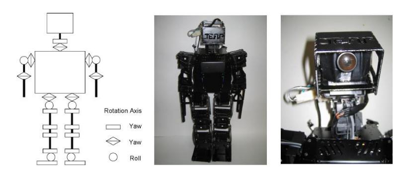
Table 1. VisiON 4G hardware specifications
| VisiON 4G | ||
|---|---|---|
| Height (mm) | 465 | |
| Weight (kg) | 3.2 | |
| DOF | 22 | |
| Actuators | VStone Servo | |
| Camera Type | Quickcam | |
| Controller | Main Controller | Sub controller |
| CPU | PNM-SG3 | VS-RC003 ARM |
| ROM | 8GB (Flash HDD) | 512 KB |
| RAM | 512 MB | 40 MB |
| OS | Linux | None |
3 Modular software environment
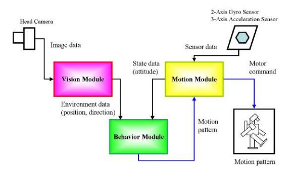
The software of the robot consists of three modules: which are vision module, motion module and behavior module. Fig.2 shows the overall system of the software. These three modules execute processing in parallel during a game.
3.1 Vision Module
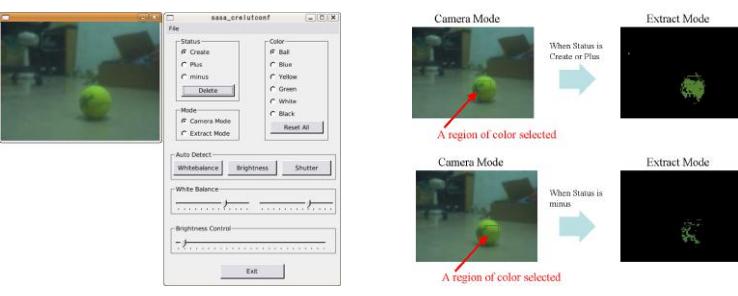
The vision module assumes to analyze image data. In the humanoid league, most teams adopt a color extraction system in order to detect the ball and the goals. This is proposed in the JEAP team as well. We use the vision module that is the original library of the image processing and we can define colors. During the game, the luminance and pixel values of colors sometimes change because of the shadow and lighting condition. In contrast, in the vision module, we can set the range of the values of each color as color tables easily at the field before the game. Then using a filter, we can detect the area of the objects independent of the small difference of the pixel values. So far, our team have taken much time to set up the camera condition and parameters of image processing in the command line before the game. Then using the Qt library, we are developing the GUI application to simplify the procedure as shown in Fig. 3.
3.2 Motion Module
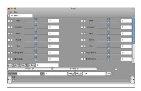
The motion module assumes to analyze sensor data and to give the motor commands to the robot. VisiON 4G has the 2-axis gyro and 3-axis acceleration sensors. The attitude of the robot, that is whether robot is down or not and if so which direction the robot is down, is detected by threshold processing of these sensor data. The motion module also receives the pattern of motion from behavior module, and gives motor commands in relation to the pattern to the robot. We use GUI application to create patterns of motion (see 4). In the GUI application, we can set the desired angle of each joint by slider bar.
3.3 Behavior Module
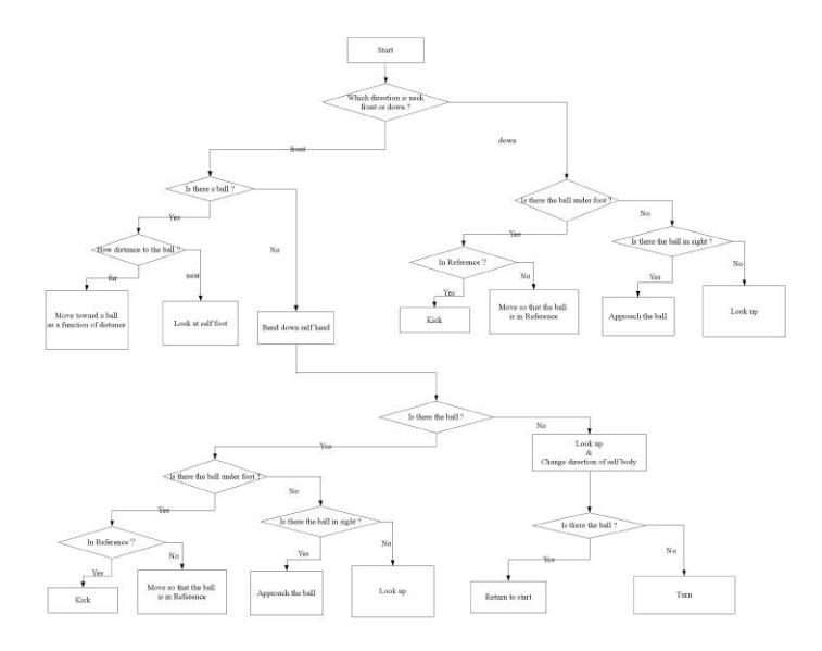
The behavior module assumes to determine the appropriate pattern of motion ,depending on the situation. We assign each strategy of behavior for each field player, which is thought to be best for soccer. As an example, The strategy of behavior for offense player is shown in Fig. 5. The behavior module sequentially receives environment and state data from vision and motion modules and selects the appropriate motion from several motion patterns, for example kicking, approaching, standing up and so on.
4 Biologically inspired control
JST ERATO Asada Project, our funding organization, studies cognitive developmental processes as they happen in natural beings like man and other animals in general. It is impractical with current technology to fully approach such a complex problem as playing soccer based on extremely purist point of view. In an effort of matching our developmental approach to the practical needs of the RoboCup competitions we tried to construct the robot behaviors in the most natural way by:
- Choosing a robot centered coordinate system: Instead of having global coordinates of any sort, we explicitly opted for using the agent's self point of view. This brings the drawback of making it difficult for the robot to make decisions based on the relative positions in the field. Despite that, the use of relative positions to the observer makes it easer to generalize the use of a determined behavior in several situations – same relative positions might repeat in several different locations of the field.
- Describing position of objects in terms of neck angles: We decided not to use newtonian distances for localization of objects. Instead, we kept all our model of the world in the natural format in which it was acquired: neck angles. Roughly speaking, pan/tilt rotations of the head are transformed into image displacements in terms of pixels and vice-versa. We took a very simplified model of a pinhole for transforming the cartesian coordinates of blobs in the image plane into pan and tilt angles for the robot. Positions of objects outside the current view field were kept for small time intervals until the robot moved the neck so as to update positions again. – Translating behaviors in terms of objects alignments and reactive behaviors. The most common soccer playing schemes were described in terms of purely reactive behaviors based as much as possible on very low level sensor data.
5 Future plans
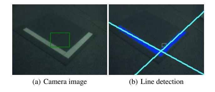
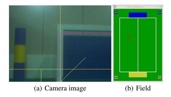
We plan to implement self-localization system into our robots using some landmarks. Then as a first step, we are developing a line-detection system by Hough transform algorithm as shown in Fig. 6. It should be useful not only for self-localization system, but also for a passing challenge. In most case, in the image space, the line can be expressed as $y = ax + b$ and plotted for each pair of image points $(x,y)$. The basic idea of the Hough transform is consider the characteristics of the line not as points $(x,y)$, but in terms of its parameters $(a,b)$. In other words, the straight line $y = ax + b$ can be represented as a point $(a,b)$ in the parameter space ($a$ vs. $b$ graph.). Moreover, by using the detected white lines and other landmarks in the field such as poll and goal, we are developing a self-localization system based on the Particle filter algorithm. This filter is usually used to estimate Bayesian models and are the sequential analogue of Markov chain Monte Carlo methods. In Fig. 7, the red points indicate the positions that are estimated by robot. Now we have a problem when the robot cannot detect enough visual clues. If there are six robots on the field, the possibility of missing the position increases. Then we are going to improve it by integrating with motor information.
Furthermore, we also plan to implement motion teaching method through physical interaction, that is "teaching by touching" system[1]. As a result of this implementation, we will be able to create motions more rapidly and to fine-tune more easily because touch is particularly appealing as an intuitive method for humans to teach robots. Since installing touch sensor will be needed in association with this implementation, this sensor data can be accessbible for detecting attitude of the robot. Therefore, we can expect to progress detection accuracy.
References
- Fabio Dalla Libera, Takashi Minato, Ian Fasel, Hiroshi Ishiguro, Enrico Pagello, and Emanuele Menegatti. A new paradigm of humanoid robot motion programming based on touch interpretation. Robotics and Autonomous Systems, 57(8):846–859, 2009.
- Norbert Michael Mayer, Joschka Boedecker, Masaki Ogino, Masaaki Kikuchi, Rodrigo da Silva Guerra, and Minoru Asada. Osaka university team senchans 2005. In RoboCup 2005 Symposium papers and team description papers, volume CD-ROM, 2005.