ZJUDancer Team Description Paper
Tang Qing, Xiong Rong, Li Shen, Zhan Jianbo, Feng Hao
State Key Lab. of Industrial Control Technology, Zhejiang University, Hangzhou, China
Abstract This document describes the RoboCup Humanoid League team ZJUDancer from Zhejiang University, China, as required by the qualification procedure for the competition to be held in Singapore, in June 2010. Full details of our robot including mechanical design, electrical design, sensors and software design are described. With this robot, we hope we could get a much better result in 2010.
1 Introduction
The robots developed by ZJUDancer for RoboCup 2010 are fully autonomous humanoid robots which play different parts as a team in the football game. ZJUDancer is established in July, 2006 to develop humanoid robot in Zhejiang University. We developed several generations of humanoid robots with which we won the champions of RoboCup China Open 2007 and RoboCup China Open 2009. We also advanced to quarter-finals in Robocup 2009 Graz. Figure. 1 and Figure. 2 show our robots in RoboCup China Open 2009.
Table. 1 shows the general specifications of our robots. Three players from ZJUDancer named Wukong, Bajie and Shaseng are fully autonomous humanoid soccer robots. Each robot is fixed to the size and weight limitations of the competition and connected by wireless networks. Referee's directions could be sent to the robot through the network. More details could be introduced in the following sections.
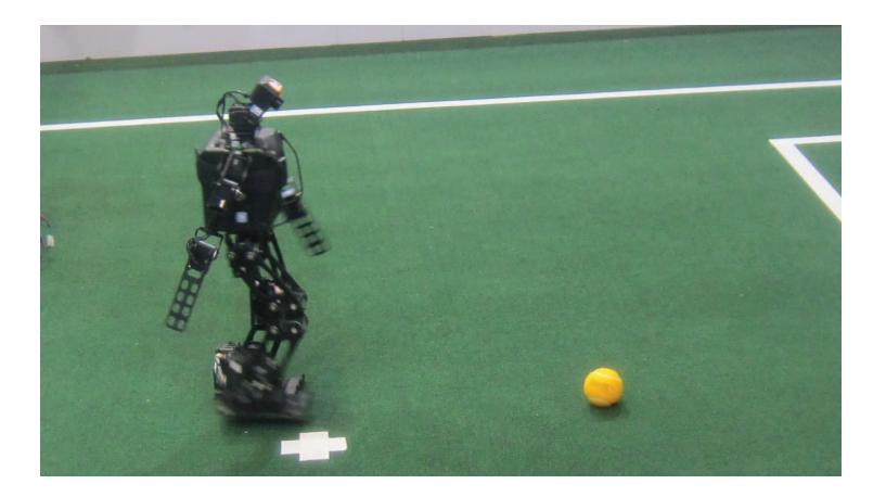
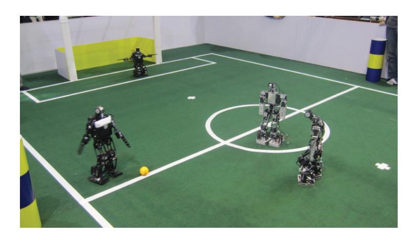
Table 1. General Specifications of the robot
| Team Name | ZJUDancer |
|---|---|
| Robot Name | Wukong, Bajie, Shaseng |
| Number of Degree of Freedom | 20 |
| Height | 58cm |
| Width | 35cm |
| Weight | 4kg |
2 Mechanical Specifications
The robot from ZJUDancer has 2 legs, 2 arms, 1 trunk and 1 head. The actuators we choose are Dynamixel RX-28 and RX-64. Each robot is driven by 20 servo motors: 6 per leg, 3 in each arm and 2 in the head. The six leg-servos allow for flexible leg movements. Three orthogonal servos constitute the 3-DOF hip joint. Two orthogonal servos form the 2-DOF ankle joint. One servo drives the knee joint. The motor distribution is different but the DOF is the same. Table. 2 shows the details. The robot's mechanical sketch could be seen in Figure. 3.
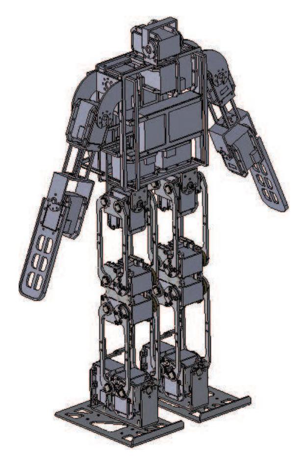
Table 2. Motor types and Distributions of DOF
| Part | Rotation Axis | Actuator |
|---|---|---|
| Neck | Yaw Pitch | RX-28,RX-28 |
| Shoulder | Roll, Pitch | RX-28, RX-28 |
| Arm | Pitch | RX-28 |
| Hip | Roll, Yaw | RX-64, RX-28 |
| Knee | Pitch, Pitch | RX-64, RX-64 |
| Ankle | Pitch, Roll | RX-64, RX-64 |
| Total DOF | 20 |
3 Electrical Specifications
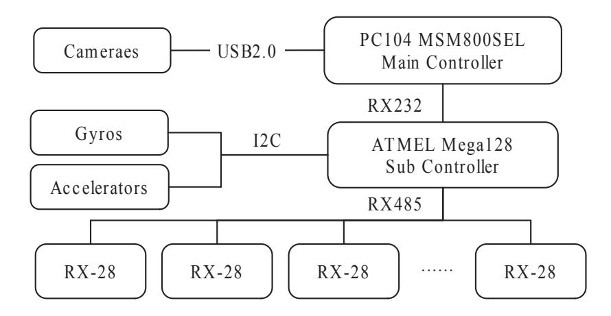
Our electrical controllers are the motor controller and the camera controller, specifications of which could be seen in Table.3. The camera controller works as the main controller processing image identification, location, strategies selection and communications. The movement and balance maintaining are implemented by the motor controller which executes the movement direction from the main controller. The total electrical architecture could be seen in Figure.4.
4 Sensor Specifications
There are 4 types of sensors equipped on our robot, which are image sensors, gyroscopes, accelerators, and potentiometers.
- Image sensor. The camera we choose is Philips SPC 900 NC. It has a frame rate up to 90 fps and the angle view of 55 degree. The camera is controlled by PC104 and the sample rate is up to 30 frames per second.
- Gyroscopes. Gyroscopes are equipped in the chest of our humanoid robot. It returns the angular velocity for the trunk of humanoid robot and helps to keep the balance of humanoid robot.
- Accelerators. This sensor detects the gravity vector when the robot is static. The main applications of this sensor is that it could be used to recognize whether humanoid robot is standing or lying down. The autonomously getting up from tipping over is depend on this sensor. On the other hand, the dynamic attitude estimate from the fusion of gyros and accelerators is under research.
- Potentiometer. This sensor detects the rotation angle of the actuator. With this sensor, the robot recognizes the current angular position of the joint. This sensor is controlled by actuator controller.
5 Software Architecture
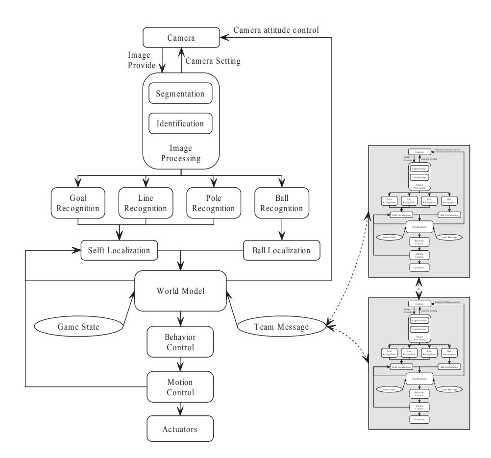
The software architecture could also be seen in Figure.5 Each robot works as an independent agent connected by team messages. The team messages could help to update the world model in each robot. We start our software design from image processing. Segmentation and identification help us distinguish each object on the playground. Localization is a complicated fusion of localization of fixed objects and robot locomotion.
6 conclusion
In this paper, we present the specifications of our robot that has two controllers and 20 DOFs. ZJUDancer has made a great progress during the last year and looks forward to making a new breakthrough in RoboCup 2010. We'd like to share our experience and have a good match with all the teams.