BI-Forward 2011 Team Description Paper
Mark Vaynberg, David Likvornik, Dotan Segall, Gal Abrass, David Hayat, Yaroslav Brustinov, Michal Weitzman, Victoria Kalmanovich, Tehila Dabush, Yaron Naor, Rafi Amsalem, Dr. Eli Kolberg
Bar-Ilan University, School of Engineering, 52900 Ramat-Gan, Israel
Abstract Team BI-Forward founded in 2010. The team consists solely of Undergraduate Students from the Bar-Ilan school of Engineering. The specifications of the Robot are provided in this paper. Our main research interests within the scope of this project are implementation of real-time image processing techniques, robot simulation, motion dynamics and camera based localization.
1 Introduction
Team BI-Forward founded in 2010 by the Bar-Ilan University school of Engineering with an aim to compete in the RoboCup 2011 Humanoid Kid-Size League. The Bar-Ilan University enjoys a successful RoboCup team in the SPL league lead by the Computer Science department(Team BURST). Team BI-Forward is composed solely of Undergraduate students under the academic supervision of Mr. Rafi Amsalem and Dr. Eli Kolberg, with the intentions to allow the students to undertake and experience a large scale project,design, implement and research dedicated hardware and tailored software algorithms.
Our goal this year is to present a worthy team which will provide the basis for an on going endeavour. These tasks include selecting the robot frame, modifying it, developing a simulator, creating a robust vision module, writing state machines for the various tasks and handling the robot gait.Each year senior Undergraduate students will build on and improve the robot functions.
2 Specifications of the Robot
2.1 Mechanical Structure
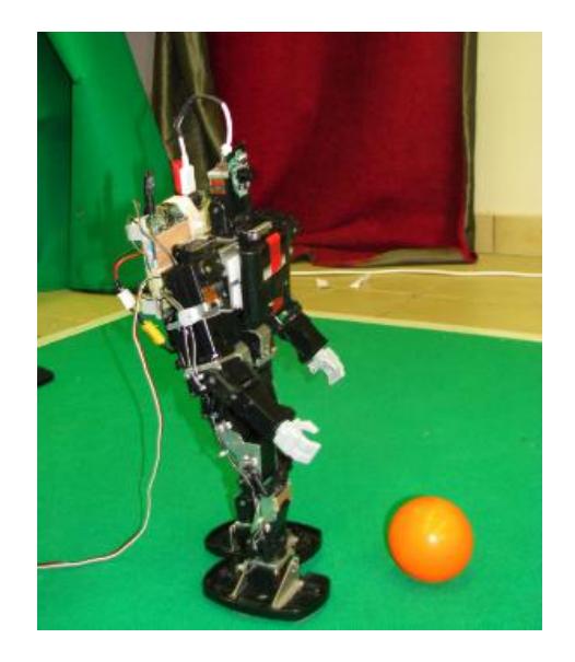
The robot used is the KONDO KHR-3HV(Figure 1) which comes with 17 degrees of freedom, modified by university to support 20 degrees of freedom as follows 6 degrees of freedom for each leg, 3 degrees of freedom for each arm and 2 degrees of freedom for the head.The robot weighs 1,700grams and its height is 42cm.
2.2 Actuators
The Actuators used are KRS-2555HV Servos with the following specifications. maximum operating angle of 270 degrees. Its speed is 60 degrees in 0.14 seconds.Servo's is weight 41.5g
2.3 Sensors
The sensors used are the standard sensors provided by Kondo with the robot, a RAS-2 dual axis accelerometer and a KRG-3 single axis gyro. The camera used is a Creative Live! Cam with a 640x480 resolution.
2.4 Controller
The RCB (Robot Control Board) provided by KONODO with the robot controls the servos,gyro and accelerometer. The main controller used is a FitPC2 board sporting a 1.6 GHz Intel Atom CPU with 1GB of RAM and a 4GB flash drive running a Linux distribution. The RCB board is connects to the FitPC via a usb connection. The camera is connected to the FitPC via usb as well.
3 Software
The FitPC runs a Linux distribution. Development is done using C++. The software is built with three layers in mind:
- Lowest layer- computation performed in each servo(actuation layer).
- Low level layer- motion generation and stability control using controller board (reflex layer).
- High level vision, world modelling,behaviour control, team coordination, etc. using embedded PC board(cognitive layer)
The striker and goalkeeper feature state machines for high level decision making. The main states include approaching a ball, goal detection, aligning in preparation for a kick and kicking the ball.
3.1 Vision
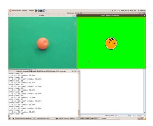
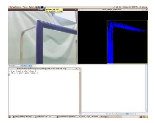
Vision was developed using the OpenCV library[1]. Trivial tasks were called from the library. In addition, the team developed and implemented tasks that were specific to the team approach. The robot retrieves a picture from the camera, and using segmentation generates binary images, one for each color of interest. These binary images are used to identify the goals, posts, ball and field markings. Once an item is identified a rough range estimation to the object is calculated based on the amount of pixels in the shape. The following images demonstrate the ball detection capability(Figure 2) and goal detection capability(Figure 3)
4 BI-Forward 2011 Team Description Paper
3.2 Localization
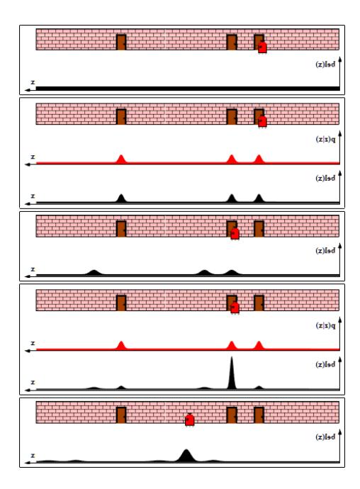
Localization is achieved investigating a deployed grid. The square with the highest probability(in accordance with triangulation methods - see next) marks the robot's location. Probability is calculated by 2 methods, which are based on either angles or distances triangulation to static objects. As the robot moves, motion engine updates the probabilities based on dead reconing odometry. Next those probabilities are modified using triangulation methods discussed above. This continues localization is often referred to as Markov localization[2](Figure 4).
3.3 State machines
The State machines run the high level logic and define the tasks of the robot. A robot can assume the role of either striker or a goalkeeper. The State machines make use of the data provided by the vision and localization.
3.4 Simulation
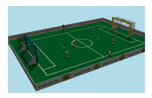
We use the Webots simulator[3] to simulate the vision, localization and state machines. We have a full model of the KHR-3HV(Figure 5)
References
- OpenCV http://opencv.willowgarage.com/wiki/
- Thrun, S., Bugard, W., Fox, D.: Probabilistic Robotics. MIT Press, USA. 2006
- Webots http://www.cyberbotics.com/overview.php