MRL Team Description Paper for Humanoid KidSize League of RoboCup 2011
Mostafa E. Salehi, Behzad Lotfi, Pooya Alamirpour, Saeed Azami Parsa
Mechatronics Research Lab, Dept. of Computer and Electrical Engineering, Islamic Azad University, Qazvin Branch, Qazvin, Iran
http://mrl.ir/index.php/humanoid
Abstract This paper presents the specifications of the hardware and software of MRL kidsize humanoid robot system which contains different parts including vision, stabilization, walking control, autonomous robot motion, planning, and modular software architecture. MRL humanoid team is developed under the RoboCup 2011 rules to participate in the soccer kidsize humanoid league competition in Istanbul, Turkey. Modular software architecture has been developed for effective implementation of modules for sensing, planning, behavior, and actions of humanoid robots. The robot has two control boards. One for walking control and the other performs image recognition, planning, and control by exploiting an embedded PC board. Our robots also have wireless LAN interface to send data including measured positions and status to other robots.
Introduction
RoboCup uses soccer as a topic of research and its ultimate goal by 2050 is to develop a team of humanoid robots that can win the human world champion team in soccer. In the humanoid league, fully autonomous robots with a human-like body and senses play soccer against each other and meanwhile handle the technical challenges such as dynamic walking, running, kicking the ball, visual perception of the ball, players, field, and also handle self-localization. The RoboCup scenario of soccer playing robots represents a challenge for design, control, stability, and behavior of autonomous humanoid robots. In a game, fast goal oriented motions must be planned autonomously while preserving the robot's stability in real-time against the quickly changing conditions.
The MRL project was started in 2003 in the Mechatronics Research Laboratory at Islamic Azad University, Qazvin branch looking onward to enhance our knowledge in robotics. Our research center has the honor to hold the RoboCup IranOpen from 2003 to 2011. MRL has eight qualified teams and has had a successful history in RoboCup for many years with small size, middle size, SPL, rescue real, virtual rescue, rescue simulation, mixed reality, and @Home teams. Since we are looking onward for new challenges to enhance our knowledge, we have decided to participate in the soccer kidsize humanoid league. Our new team is a step towards research and development of robots which offer more real human-interaction.
Our developments for the kidsize humanoid robot include the design and construction of modular software architecture on a powerful single board computer developed for robotics applications [1]. The project is described in two main parts: hardware and software. The software contains robot applications including autonomous motion and walking controller, self localization base on vision, planning, and communication. The hardware consists of the mechanical structure and the driver circuit board. Each robot is able to detect the ball and goal by scanning the field, walk towards the ball, and kick when it catches the ball. The project is still in progress and some developed methods are described in the current report.
As we attend the kidsize humanoid league for the first year, we need to make a solid knowledge background. Therefore, our mission is to fulfill 3 fields of study in terms of motion control, vision, and artificial intelligence. The first part is to study the humanoid robots movement with 20 servo motors by determining how to balance the robot and control its orientation. The other part is to design and develop an embedded platform which is placed at the chest of robot to process digital image and interpret data from the vision system. At present we use the RoBoard RB-110 [1] as a developed single board computer. The remaining study is to improve our knowledge and experience in developing different algorithms.
2. Overview of the System
We have used the comprehensive kit robot of bioloid [2] and the kinematic structure with 20 DoF can be seen in Fig.1. The actuators used in our robots are the Dynamixel servo motors. The motion mechanism consists of 20 degrees of freedom distributed in six per leg, three per arm and two degree of freedom moving the neck horizontal and vertical. Physical specification of the robot is illustrated in Table 1. To facilitate exchange of the players, all robots use the same physical structure.
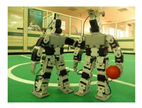
Table 1. Physical measurements of the robot
| Property | Value |
|---|---|
| Height | 41 cm |
| Weight | 2.16 Kg |
| Walking Speed | 0.03 m/s |
| Degrees of freedom | 20 in total |
| Servo motors | 20 AX-12 |
| Sensors | ITG-3200, ADXL330, and FSR |
| Embedded PC board | RoBoard RB-100 |
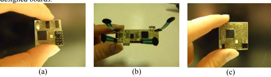
The robots are equipped with an A4Tech webcam camera and distributed computing hardware, consisting of a controller-board for motion-generation and stability control and an embedded PC board for all other functions. The PC board as the main CPU board supports planning and vision and consists of a RoBoard RB-110 based on Vortex86DX a 32bit x86 CPU running at 1GHz with 256MB DRAM. For motion stabilization a 3-Axis Accelerometer, 3-Axis RS485-compatible Gyro, and force sensitive resistors (FSR) sensors are used. The robot also contains 20 AX12 servo motors and batteries.
The camera sends image signal to the main CPU board. The CPU processes the image data to detect positions of ball, goal, other robots and landmarks. From these positions, the robot estimates its own position. We also have implemented a wireless communication between the robots. We exploit the vision and network data to selects the next behavior of the robot according to the robot role and the priority of the behaviors. The defined behaviors are composed of simple motions to support complex tasks such as ball perception, going to target, and …. The action command of each motion is sent to the controller board which decodes and executes the command. If the command is a kind of moving the body or checking a status, the controller sends a command to servo motor via RS485 interface. Each servo motor has its own CPU to control motor and receive/send commands. The command includes the ID number of the motors and is sent to all servo motor. If the command is related to servo motor, it decodes and executes the command.
3. Gait and Motion Control
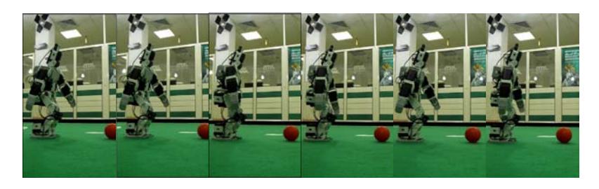
Stabilizing humanoid robots is a challenging subject and has attracted many researchers and one of the significant features of each robot is its mobility and stability. In our system, we have generated both online and offline robot gaits. Offline gaits are such as kicking, standing up from fall and other common motions. For online gait generation, for example, we use the data of the vision to find the ball position and turn the neck to locate the ball in the center of the image in real-time. For offline motions we use robot position frames which are defined by joint positions and then implement inverse kinematic to convert from observed positions to obtain a set of robot joint angles. Through inverse kinematics and a trial and error process, we have found the proper angles to walk robustly. Its maximum speed is approximately 3cm/s. Stability control is based on the robot's gyroscope and acceleration sensors and the controller receives data from these sensors via A/D converter. According to these data, the robot detects a fall and prevents fall. The robot does not fall practically; however, when the robot falls because of other robots pushing, it detects the fall and stand up smoothly. The robot can stand up from lying on its back or its front side. Motion control process is shown in Fig.2.
4. Software Architecture
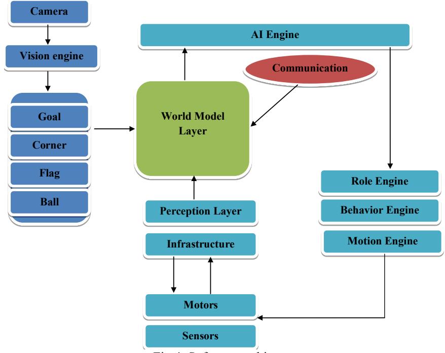
In our software hierarchy information processing is distributed into multi layers. The lowest layer of computation (infrastructure) is performed in each of the 20 servo motors. Every servo motor is equipped with a microcontroller for position and velocity control. Hard real-time tasks like motion generation and stability control are executed on the controller board and high level control like AI, vision, world modeling, behavior control, and team coordination is executed on main CPU. Fig.4 shows the block diagram of the software architecture which runs on the robot's main CPU. The main blocks of the program are:
Infrastructure: Contains all low level routines for accessing sensors and actuators.
Vision engine: Contains camera direction control and image processing algorithms such as object recognition and position estimation.
World model: The world model consists of a set of models which are updated using the information from the vision, and gathered data form perception layer and network (communication) module. A model is defined for almost every object. A selected subset of information from the models is exchanged between all robots of the team via wireless LAN.
Motion control: The current motion module is mainly used to calculate walking trajectories (see Sect. 3) and to control the neck joints with two DoF. The control of the other joints in the arms aims to improve stability during walking and kicking.
Behavior engine: The data provided by the world model is used to control more complex behaviors required for playing soccer autonomously. The main task is decomposed into subtasks until they can be described as a set of atomic motions which can be executed by servo motors. The atomic motion actions are transferred to and interpreted by the motion module.
AI engine: Planning system of the robot is based on a multi-layer structure. The layers are named AI, Role, Behavior and Motion. Each layer contains a scenario which runs in parallel with the scenarios in the other layers. A decision in a higher level can terminate and change the scenario running in lower level.
Communication: Mainly responsible for the wireless communication of the robot with the other robots or the referee box via WLAN.
5. Image Processing and Position Estimation
Vision is one of the crucial interfaces for robots to observe the outside world and realize situations and conditions [6]. To achieve an extendable vision system for different camera types, the vision module can process images in different color spaces with different resolutions by choosing a highly object oriented approach. The vision engine can be divided into two parts: image capture device and image processing center. We use one A4Tech camera as an image capture device and our vision algorithms are mainly based on colors and the images at resolution 640 x 480 in RGB format are processed 30 frames per a second.
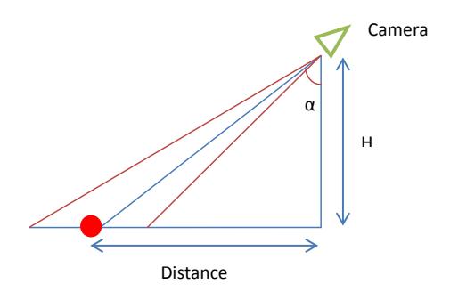
The object positions relating to the robot are determined and measured according to the land mark positions. The position of the robot is estimated and the robot will try to localize itself from this data. Fig.5 illustrates the distance estimation technique based on the height and angle of the neck.
References
- RoBoard RB-110 Single Board Computer, available online: http://www.robotshop.com/roboard-rb-110-single-board-computer.html
- Bioloid Comprehensive Kit available online: http://www.trossenrobotics.com/bioloid-comprehensive-robot-kit.aspx
- ADXL330, datasheet, available online: www.alldatasheet.com
- ITG3200, datasheet, available online: www.invensense.com
- FSR an Overview of the technology, datasheet, www.Techstorm.co.kr
- Rafael C. Gonzales and Richard E. Woods, Digital Image Processing, Prentice Hall, 2001.