Hanuman KMUTT: Team Description Paper
Wisanu Jutharee, Sathit Wanitchaikit, Boonlert Maneechai, Natthapong Kaewlek, Thanniti Khunnithiwarawat, Pongsakorn Polchankajorn, Nakarin Suppakun, Narongsak Tirasuntarakul, Thossaporn Phetruphant, Anon Poungrat, Tana Wichito Suriya Natsupakpong, Thavida Maneewarn
King Mongkut's University of Technology Thonburi, Institute of Field Robotics (FIBO) 126 Pracha u-tid Rd., Bangmod, Thungkru, Bangkok 10140, Thailand
Abstract This paper describes the design and development of the kid-sized humanoid robots of the Hanuman-KMUTT team for RoboCup 2013. The new locomotion subsystem both hardware and software are implemented in our humanoid robot this year to add the omni-directional walking capability to the robots. With this improvement, the robot should be able to approach the ball faster at greater precision. We also improve the vision and localization module which multiple visual landmarks are used to identify the location of the robot in the game field.
1 Introduction
Institute of Field Robotics(FIBO) at King Mongkut's University of Technology Thonburi (KMUTT) has developed the humanoid robots to participate in RoboCup humanoid kid-sized league since 2005 under the name 'Team KMUTT' and later on 'Team Pheonix'. This year, our team 'Hanuman-KMUTT' has won Thailand Humanoid Soccer Robot Championship and prepared to participate in RoboCup 2013 in the Netherlands. The word 'Hanuman' came from the well-known monkey character from the classical literature 'Ramayana'. Therefore, all robots in our team are named after the monkey characters in Ramayana. The monkey represents agility in motion and quick-witted intelligence.
In this paper, we will describe the recent development of our kid-sized humanoid robots. Section 2 gives an overview of the system design in our robots: striker and goalie. In section 3, the improved locomotion control subsystem of the robots will be explained. Section 4 discusses the vision based navigation and localization. Section 5 is about the game control and decision-making system. The last section concludes the paper.
2 System overview
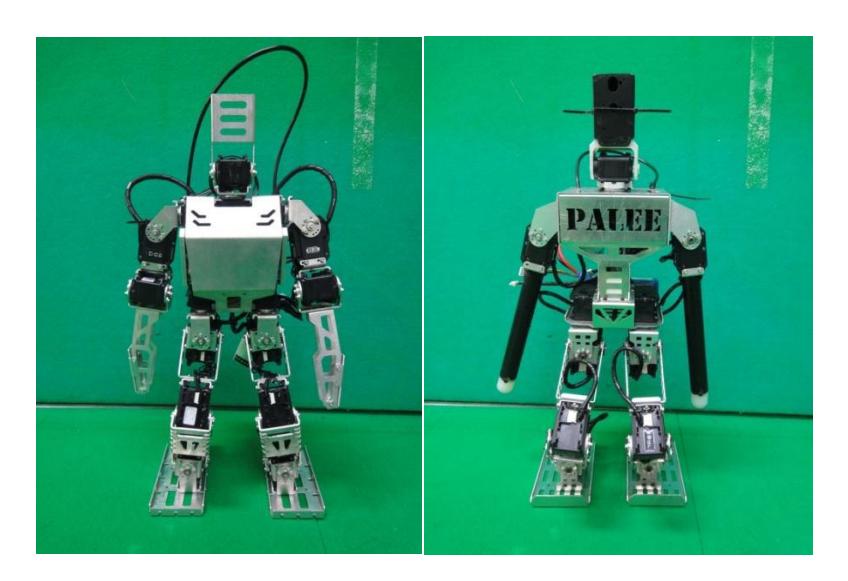
Our team has 5 robots: Hanuman, Tripetch, Muchanu for striker and KM2, Palee for goalie as shown in Fig 1. Each robot is composed of mechanical hardware, sensors, and computing hardware. The structure of all robots is made of aluminum alloy sheet metal. Each robot uses 20 servo-motors (details are provided in the robot specification sheet).
All striker robots use the same set of sensors. These are 9dof IMU (Sparkfun Sensor Stick SEN-10724) and a Logitech USB camera. The camera installed on the robot is a single lens USB webcam which has the horizontal field of view at 60 degrees. The capture resolution is 640x480 pixels. The workspace of pan-tilt unit is - 120 to 120 degrees in panning and 0 to -80 degrees in tilting. The accelerometer tells the robot if there is any longitudinal and/or transversal tilt. The three rate gyros measure angular velocity in three axes of rotation. Kalman filter is used to estimate the body angle from gyro and accelerometer information. The angular position and velocity information will be used to adapt the attitude of the body during walking. The camera is used to track the ball and other objects of interest, which is crucial for navigation decision-making software.
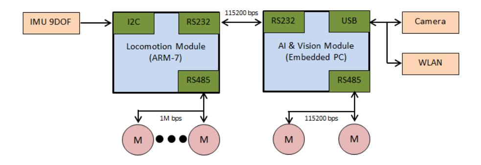
The main computer for the striker robots are the PICOITX (PICO820) SBC with ultra low power Intel AtomTM processor Z500 (1.6GHz CPU) . The PICO820 board computer receives information from the CCD camera via the USB port. The computer computes the walking path and sends locomotion command to the ARM 7 (60MHz RISC microprocessor) motor controller via RS485 port as shown in Fig 2.
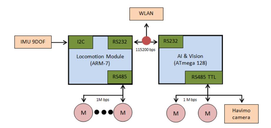
The goalie robot is a micro-controller based system. The AVR ATMEGA1028 controller board is used for high-level decision-making. The camera installed on the robot is a HaViMo camera which has the capture resolution of 640x480 pixels. The workspace of pan-tilt unit is -120 to 120 degrees in panning and 0 to -80 degrees in tilting. The IMU is used for computing the longitudinal and/or transversal tilt. The locomotion is controlled by the ARM 7(60MHz RISC microprocessor) motor controller via RS485 port. The leg trajectory and balancing controlled is computed in the ARM 7 controller. The robot detects the position of the ball using the HaViMo camera and activates the falling motion according to the direction of the ball. The striker robot communicate with the rest of the team via a UART-WiFI module as shown in Fig 3.
3 Locomotion system
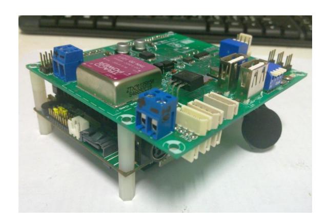
The recent development for our robot locomotion is the addition of the omnidirectional walking capability. In the past, our robot walking commands were designed into different walking gait such as, forward step, backward step, turn, slide and turn-around-ball. The high level control decides the walking command and specifies the time duration or the distance of each command as the command parameters. In the new walking control, the high level sends the control input in form of planar velocity (Vx, Vy) and angular velocity (ω) to the low level locomotion module. The locomotion module will map the input velocity value to walking gait parameters and generate the desired trajectory for all motors in each legs using 6 DOF inverse kinematics and then convert these trajectories into command for the servo motors as shown in Fig 4, and Fig 5 shown new design of locomotion module board.

4 Vision based navigation system
To interact with any objects in the soccer field, the robot shall be able to distinguish and identify many types of objects in the playing environment. These objects are the ball, goals, opponents, and teammates. Moreover, other useful information associated with the objects such as position and speed shall be determined. Once the information is determined, the robot can compute an appropriate action for the soccer game. The following subsections describe how the robot recognizes the objects in the game and compute the position of the objects.
4.1 Object Recognition
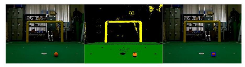
As specified by the rule, the objects in the field have different color. Thus we can roughly distinguish each object type by implementing color segmentation technique. The segmentation algorithm used in our robot is based on CMVision [1]. Because HSV color space is more sophisticate for defining color description by human compare to RGB or YUV color space. Therefore we modified the original algorithm which uses YUV color space as input to HSV color space model. The segmentation result can be shown in Fig 6.
The above result is used as search region to investigate further identification. For example, all orange segments are fed to circular fitting algorithm to evaluate the amount of circular distortion. The segment which given the least distortion is interpreted as the best ball candidate for that captured image. With other similar shape evaluation algorithm, we can find the best candidate for the goals, field markers, opponents, and teammates as well.
4.2 Position Determination
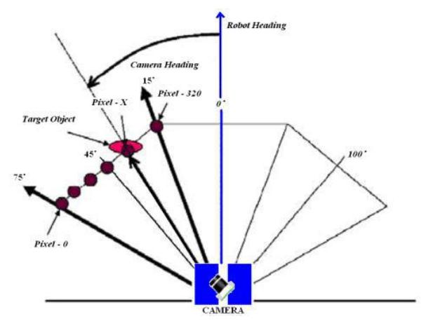
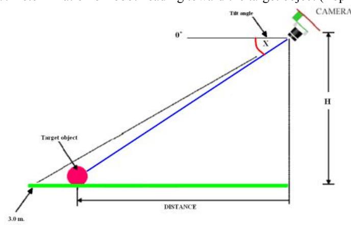
The 2D positions of all identified objects from the previous section are used to compute the positions of all interested objects referenced to the robot. By associate the 2D position of the image frame with the robot configuration (head height, head tilt angle, and head pan angle), the 3D positions of the objects can be estimated by implementing trigonometry technique. Using this method, we assumed that all objects always are on the field ground. The intrinsic and extrinsic parameters of the camera shall be determined beforehand, so that the error from optical distortion can be minimized. The position determination can be illustrated by Fig 7 and Fig 8.
5. Game Control and Decision-making
(No introductory text in this section)
5.1 Game controller
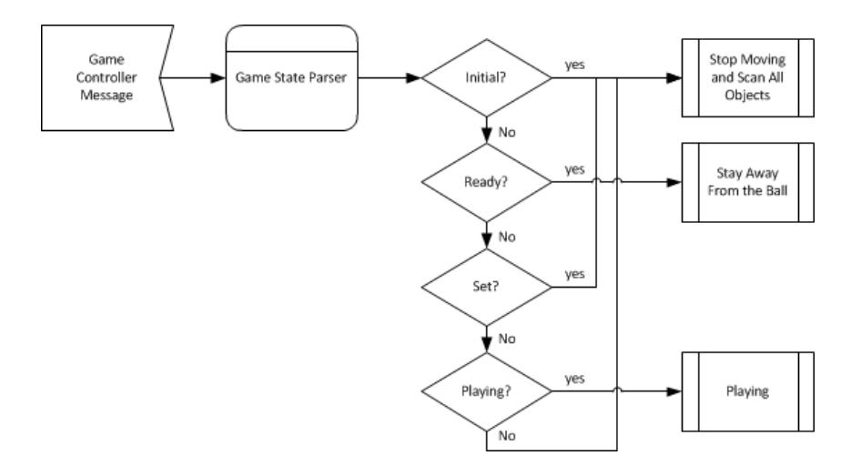
To control the operation during the game, all robots continuously receive the neutral control message from the referee's game controller. When the received message indicates the change of the game state, the current operation is terminated. Then the robot loads the new operation which associated with that state. This process can be illustrated by Fig 9. In case the wireless network provided by the organizer is not available, the operation mode can be manually selected by the mode selector buttons installed on the robot.
5.2 Decision Making System
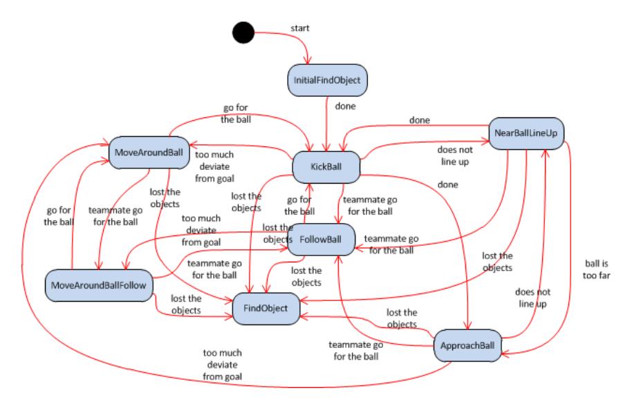
The decision making system of all striker robots can be described by the finite state machine illustrated in Fig 10. The conditions for state changes of each state are determined based on the observation data from the vision system and internal sensor reading of the robot. In addition, the robot shares this information among the teammates by broadcasting mechanism via WLAN network. Therefore, the robot can cooperate to score the game as a team. The goalie decisioning can be described in a simpler state machine. The goalie is constantly looking for the ball, if the ball is heading toward the goalie on either the left or right direction, the goalie will fall in that direction to block the ball then get up and move toward the original position.
5 Conclusions
This year, our team's goal is to develop the humanoid robot system that can move fast and make decision quickly like 'Hanuman', the monkey character in Ramayana . We are focusing on designing and building the new low-level control subsystem and the new locomotion with omnidirectional walking capability. These robots can perform different motions such as walking and turning more smoothly and more stably. We also have an improvement in our vision-based navigation system to be able to cope with more difficult localization requirement of this year competition.
Acknowledgements
Hanuman-KMUTT would like to thank Seagate Technology Thailand and King Mongkut's University of Technology for the team's financial support in RoboCup 2013.
References
- Bruce, J.; Balch, T.; Veloso, M.; , "Fast and inexpensive color image segmentation for interactive robots," Intelligent Robots and Systems, 2000. (IROS 2000). Proceedings. 2000 IEEE/RSJ International Conference on , vol.3, no., pp.2061-2066 vol.3, 2000