Bold Hearts Team Description RoboCup 2014 Kid Size
Sander van Dijk, Drew Noakes, Daniel Barry, Daniel Polani
Adaptive Systems Research Group School of Computer Science University of Hertfordshire, UK
http://www.github.com/sgvandijk/libbats
Abstract In this paper we describe the RoboCup Humanoid Kid Size division of team Bold Hearts, the RoboCup team of the University of Hertfordshire, in Hatfield UK. We discuss construction and aspects of our software architecture, as well as some of our solutions to important problems such as vision, localisation, action selection, and communication. Finally, we provide an overview of the relevant experience and achievements of our team.
1 Team and Robots
Team Bold Hearts, from the Adaptive Systems Research Group at the University of Hertfordshire, UK, has participated in RoboCup since 2002. Initially solely in the simulation leagues, we spread out to the kid-size humanoid hardware league 18 months ago. To facilitate this step, we have chosen the popular DARwIn-OP robotic platform to make up our robotic team. Currently we use this platform unchanged, i.e. they conform to their original specification; our focus has been on the software controlling them. Starting from the Robotis DARwIn-OP software supplied with the robots, we have replaced many parts with our own implementations, with the gait module being the main part still mostly in its original form. Additionally, we used the libbats framework originally developed for the 3D simulation league, which our team members released and maintain as an open-source project.
To the best of our knowledge team Bold Hearts is currently the only team working on both Soccer Simulation and Kid Size challenges. This puts us in a good position to transfer experience between the leagues. With this in mind we strive to keep using a shared code-base and framework for both leagues. The remainder of this paper will outline some of the most important aspects of this framework as they apply to the kid-size league.
2 Software Architecture
The agent employs a modular, multi-threaded architecture implemented using both C++ and Python. With the first used for low level control and sensor processing, and the latter for higher level control, this combination strikes a balance between efficiency and ease and speed of development.
The core of the framework consists of two control loops: one high frequency loop for motion control (125Hz), and one slower loop that controls vision and behaviour generation (30Hz). An overview of these two main threads of operation is provided in the following subsections, with more detailed discussions of some aspects given thereafter.
2.1 Cognition
The cognition thread loops through a set of operations at a rate goverened by the camera, achieving 30Hz on our hardware and utilising every available image. Camera frame data is processed to find visual features, which are then projected into a 3D coordinate system relative to the agent. The localiser is updated using odometry derived from forward kinematics, filtered IMU data and the observed objects. With this revised posture estimate, the position of the agent and other dynamic objects are calculated in the World Frame.
Having integrated the latest perception of the environment, the behaviour subsystem runs, which results in target actions for the high frequency control loop. These actions consist of motor trajectories, and periodically also includes data to be transmitted to team mates via UDP.
A more detailed discussion of these different parts of this cognition process are given below.
2.2 Hardware Communication
The DARwIn-OP uses a CM730 subcontroller for motors, accelerometer, gyroscope, buttons and LEDs. A dedicated, real-time priority thread has exclusive access to this subcontroller, marshalling all communication efficiently along its bus.
With an update period of 8ms, the hardware loop runs with a frequency of 125Hz. Each cycle, the instantaneous position, temperature, load, voltage and alarm state is read from all 20 motors, along with the accelerometer and gyroscope readings. This data is provided to several motion modules, when active, which perform locomotion, head control and scripted motion playback. Target positions and PID gain values generated by these motion modules are transmitted to the motors. Any change to the status LEDs are also written at this time, as a means of communicating certain important states to the robot handler.
2.3 Configuration
We use a tiered configuration system divided into the following levels: Agent configuration, Location / Event configuration, and Team configuration. Configuration settings of higher levels can override those set at lower levels.
Configuration values are strongly typed and limited to within sensible ranges. Values of most configuration settings may be modified at run time via our debugging tools, allowing convenient, interactive and rapid evaluation of parameters online.
2.4 Debugging
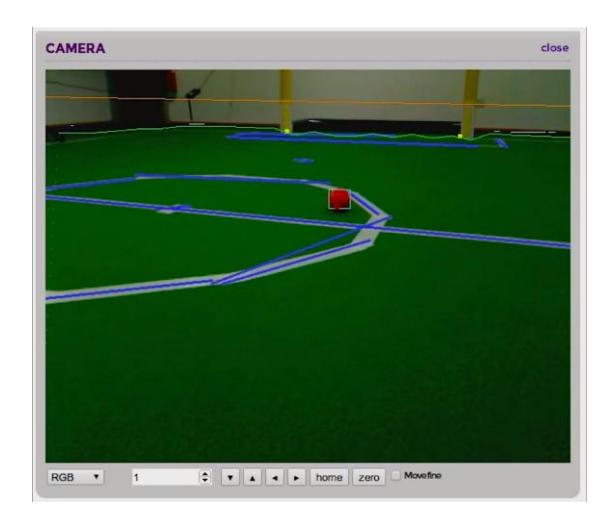
For debugging we built an HTML5 application which runs in modern browsers and is served directly from the robot via HTTP. The core state of the agent is modelled as a set of immutable state objects, and each of these objects is exposed from the agent via WebSockets. Our debugger subscribes for updates to whatever state objects are required for the particular task at hand.
Further, most configuration settings are able to be modified using this browserbased tool. Examples include watching the live video feed, viewing real-time charts of IMU data, 2D and 3D models of the agent's local and world frames, behavioural reasoning, game state and detailed per-thread timing breakdowns just to name a few.
The website is served directly from the robot. This approach makes it possible to debug using any device with a recent web browser, with the debug interface always up to date with the software running on the robot.
3 Vision Pipeline
The vision system provides some of the most critical data for building the agent's belief about the state of its environment. Our computer vision code has been carefully optimised to achieve the full 30 frame per second capability of our camera.
Moreover, since the 2013 world cup in Eindhoven we have increased the resolution of the image being processed from 320x240 to 640x480 pixels. This allows us to discern details at greater distances, which experimentation showed would be necessary on the larger field dimensions used this year. This doubling along both image axes results in four times as many pixels to process. To maintain our frame rate, we now sample selectively from the camera frame, giving us control over the number of pixels to consider. The technique we use applies a uniform spacing across the ground plane relative to the agent. Consequently the greatest pixel density is maintained at great distances, while sparse sampling occurs in the foreground where objects are largest on the camera plane.
From each image we extract the ball position, goal post positions, and field lines. Additionally, we have multiple techniques for estimating both the visual horizon and the edge of the field which assists in preventing incorrectly identifying objects outside the predictable, controlled environment of the field where objects must be assumed to be of all shapes, sizes and colours.
A colour look-up table is produced offline for use during competition matches. The pixels of each camera frame are labelled accordingly. These labelled pixels are processed by all vision subsystems in a single pass, optimising the performance of data caches.
For object detection we use a run-length encoding which is subsequently processed using a disjoint set to build up contiguous regions. Our line detection strategies include a progressive probabilistic Hough transform, and a linear regression model. Each of these methods can be configured and swapped with different implementations on the fly using our debug tool, to make the process of experimentation and configuring during the set up phase of a RoboCup event as efficient as possible.
4 Localisation
Determining its location in the field is one of the most important challenges for a football playing robot, especially with the humanoid league moving further and further away from a small, conveniently colour coded field. In the simulation league, we had developed a robust Kalman filter solution, however to be better able to deal with more challenging real world scenarios, we switched to a Monte Carlo, particle filter based implementation for the hardware league. However, still incorporating it in the shared framework meant we could transfer over several parts, and conversely verify the implementation in a controlled environment. The following two sections briefly describe the two steps that the particle filter comprises.
4.1 Prediction
Firstly, each particle is updated to predict the new location, based on its previous state and a motion model that describes the change of location based on odometry. This motion model is based on two parts: forward kinematics and IMU readings. The first calculates the change in location of the stance foot of the robot to its torso using motor position measurements and a model of the robot's body.
The second part integrates measurements of the tri-axes gyroscope and the accelerometer to further keep track of the orientation of the robot, using a gradient descent based algorithm. This algorithm operates on quaternion descriptions of the orientation of the robot and of the change thereof. Given a reading of the angular rate around each of the three axes ω = [0 ωx ωy ωz], the change of rotation in quaternion form can be calculated as q˙ω = 1 2 q ⊗ ω, where q is the current rotation and ⊗ signifies the quaternion product. An orientation estimate can then be maintained by integrating this change over time. However, measurement noise and a limited measurement period will induce error of the estimate growing over time. To help overcome this, the accelerometer reading is incorporated into the estimate: it provides an error measurement as the difference between the observed field of gravity and that expected given the current orientation estimate. Posing this error as an objective function to minimise using gradient descent results in a simple update rule:
$$\boldsymbol{q}{est} = \gamma \boldsymbol{q}{\omega} + (1 - \gamma) \boldsymbol{q}_{\nabla}$$
where q∇ is the orientation found by performing a gradient descent step, and γ ∈ [0, 1] is a trade-off parameter. It turns out that a single gradient descent step at each cycle, rather than performing steps until convergence which would be too expensive, is sufficient to minimise the error over time.
4.2 Update
After the prediction step, the predicted locations are weighted based on how well the observation acquired from the vision pipeline described above match the expected observations given the particle. Finally, resampling is done when the effective sample size (ESS) becomes too low, indication that there are too many particles that do not add to the estimate, where the ESS is proportional to Σi w2i.
5 Behaviour and Action Selection
In this section we will discuss our behavioural framework, which has grown out of the experience obtained in the simulation league where the focus lies heavily on this aspect of the RoboCup challenge. From this experience we have extracted some properties that a useful behaviour framework should have: it should be highly modular so separate parts can be developed in parallel, different pieces of behaviour can easily be reused, and behavioural solutions with different implementations can be interchanged; it must be as nonrestrictive as possible, as not to hit future limitations; hierarchy is important, to be able to build up complexity over time; and finally it must directly enable the use of well developed machine learning techniques.
Our behavioural framework is based on the so-called Options model. The final outcome of a behavioural framework is the selection of primitive actions: actions that are instantaneously executed, usually once per some defined time step, or think cycle. In our scenario these actions consist of direct motor control, or acts of communication. More complex behaviour however consists of tightly connected series of such basic actions, and to make such behaviour feasible it must be described in the form of higher levels of abstraction. An option is such a higher level abstraction of an action, specifically forming an abstraction over time: an option is not necessarily instantaneous, it can be active over a length of time.
Formally, an option is described by three components: an initiation set I that determines in what states the option can be selected; a policy π that describes the action selection when this option is selected; and a termination condition β that (stochastically) determines when the option ends. The case where the policy directly selects primitive actions amounts to a single level of abstraction. However, one can also allow the selection of other sub-options, incurring a recursion that forms an unlimited hierarchy. Finally, primitive actions can be modelled as options that always terminated after one step, ensuring we an use a single structure throughout the whole hierarchy.
Algorithm 1: ExecuteOption
Require: < I, π, β >
1: repeat
2: Observe current state s
3: Select sub-option o ∈ I according to probability distribution π(s, ·)
4: ExecuteOption(o)
5: until β(s) ≥ U(0, 1)
The Option model was first formulated in the context of Reinforcement Learning, and has been used and further developed in that area of research extensively for the last 15 years, which will allow us to apply and further develop this work in the context of RoboCup. However, the framework is abstract enough to allow for a multitude of implementations of the options. For instance, the ubiquitous finite state machine is, in our framework, implemented as an option where the policy is determined by the state of the machine, and the termination condition is triggered by the state machine transiting into some final state. Other action selection mechanisms such as artificial neural nets or decision trees fit into this framework just as easily.
6 Communication
We incorporate a non-blocking open UDP standard of communication between robots that is currently being developed by the FUmanoids under a grant from the RoboCup federation. This allows the bots to reliably transmit information about their current location and orientation relative to the global coordinate frame, observations made relative to the robot's local frame, the role in the team including confidence in those values and much more.
This will make communication between players of different teams standardised, therefore allowing them to communicate and participate in mixed teams, which would open the way to new research directions of interest to our group and could support the growth of the hardware league to large teams with high level play.
7 Simulation
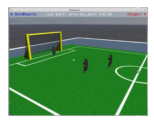
Using simulation can make testing and optimisation much faster. As an example, our team has previously used simulation to perform large scale optimisation of gait speed under energy constraints. Given our background in the 3D simulation league, including providing active development of the official simulator as members of the league's Maintenance Committee for many years, the obvious choice was to use this simulator, SimSpark/RCSSServer3D, within our hardware team. As such, we have ported a model of the DARwIn-OP, as well as the kid size arena, to this platform. Figure 2 shows a screenshot of the simulator running a team of robots using this model.
Currently this integration is still in an early stage: the model needs to be improved further to be able to use the simulation for realistic physical testing and optimisation. This opens up several interesting paths of research, possibly involving bidirectional optimisation between simulation and in the physical scenario. Furthermore, this work may directly feed back into the simulation league, to support the effort of moving the leagues together. However, the current state already allowed us to help test our localisation method as mentioned above, as well as our behaviour structure.
8 Experience and Achievements
Team Bold Hearts has strived to build up as much experience as possible in the short period of time since we joined the humanoid league. During the competitions we have attended we performed our referee duties, with most of our current team members having this experience and full knowledge of the rules. Besides these official RoboCup events, we have also participated in several RoboCup workshops with German and UK teams. We anticipate attending a meet up in Berlin this March, as well as the German and Iranian Opens in April.
The following are the detailed achievements and contributions of team Bold Hearts of the last five years, both in the Simulation League (SL), and in the Kid-Size League (KSL).
- Achievements KSL: 3rd German Open 2013, Magdeburg, Germany; Qualified RoboCup World Championship 2013, Eindhoven, The Netherlands (KSL)
- Selected achievements SL: 2nd RoboCup World Championship 2009, Graz, Austria; 3rd RoboCup World Championship 2012, Mexico City, Mexico; 1st German Open 2009, 2010; 1st Iran Open 2011; 2nd Dutch Open 2012
- Members SL Technical Committee 2009, 2011, 2012
- Chair SL Organising Committee 2010, 2013
- Awarded RCF sponsored project 'Boosting the 3D SSL Simulator'
References
- George Konidaris and A.G. Barto. Building portable options: Skill transfer in reinforcement learning. In Proc. of the 20th Int. Joint Conf. on AI, pages 895–900, 2007.
- O Kozlova, O Sigaud, and C Meyer. Automated discovery of options in factored reinforcement learning. In Proc. of the ICML/UAI/COLT Workshop on Abstraction in Reinforcement Learning, pages 24–29, Montreal, Canada, 2009.
- Valerio Lattarulo and Sander G. van Dijk. Application of the "alliance algorithm" to energy constrained gait optimization. In The 15th Annual RoboCup International Symposium, pages 393–404, Istanbul, Turkey, 2011.
- S.O. Madgwick, A.J. Harrison, and A. Vaidyanathan. Estimation of IMU and MARG orientation using a gradient descent algorithm. In IEEE Int. Conf. on Rehabilitation Robotics, page 2011:5975346, 2011.
- A. McGovern and A.G. Barto. Automatic discovery of subgoals in reinforcement learning using diverse density. In ICML 18 2001, pages 361–368, San Francisco, CA, USA, 2001. Morgan Kaufmann Publishers Inc.
- Özgür Şimşek and Andrew G. Barto. Skill characterization based on betweenness. In D. Koller, D. Schuurmans, Y. Bengio, and L. Bottou, editors, Advances in Neural Information Processing Systems 21, pages 1497–1504, 2009.
- Richard S Sutton, Doina Precup, and Satinder Singh. Between mdps and semimdps: a framework for temporal abstraction in reinforcement learning. Artificial Intelligence, 112(1-2):181–211, 1999.