Berlin United FUmanoids Team Description Paper for RoboCup 2017
Jan Draegert, Simon Gene Gottlieb, Michael Pluhatsch, Arne Schmidt, Till-Julius Krüger, Anahid Roshandel, Christopher Mühl, Raúl Rojas
Institut für Informatik, AG Intelligente Systeme und Robotik, Freie Universität Berlin, Arnimallee 7, 14195 Berlin, Germany
http://www.fumanoids.de · http://www.fumanoids.de/opensource · http://www.fumanoids.de/publications
Abstract This Team Description Paper describes the humanoid robot team Berlin United FUmanoids and presents robots for participation in RoboCup 2017 in Nagoya, Japan. A general overview of the team and its history will be given as well as insight into research interests and particular areas of the robots' software and hardware.
1 Introduction
Berlin United FUmanoids is a humanoid robot team participating in the Humanoid KidSize League at RoboCup. The team was founded in 2006 as the successor of the Mid- and SmallSize team FU-Fighters.
During the time of participation at RoboCup, the team had signicant successes in competitions, achieving 2nd place in 2009 and 2010, 3rd place in 2007, 4th place in 2011 and reaching the quarter nals in 2008, 2012, 2013 and 2015. 2014 and 2015 the team scored 1st place in the RoboCup German Open competitions. At the Iran Open 2014 the FUmanoids scored 1st and 2016 3rd.
This paper presents the team's research interests, contributions to the Robo-Cup community as well as the hardware and software of the FUmanoid robots.
2 Research and Contribution
The main research interests are:
- decentralized control architecture for humanoid robots
- reliable classication of YUV triples as logical colors, even when lighting conditions change
- real-time capable vision and detection algorithms for soccer games
- fast and stable walking
- development of sophisticated hardware to perform low level diagnostics of the overall system
The team is committed to promote RoboCup, the Humanoid League and the research exchange between teams. For this reason the team is one of few Humanoid League teams that releases their source code, schematics and designs for hardware components on a regular basis. The software releases consist of FUmanoid, the main program running on the robot. Each release resembles the software and hardware used in the previous RoboCup championship. Additionally, the developed framework is also released. The custom built hardware is part of the release as well as the software running on the microcontrollers. Theses and papers on the robots are available on our website.
3 Hardware
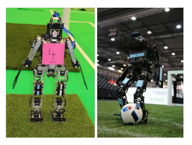
We use two dierent robot architectures. One called the 2013-Platform and the other called 2016-Platform (see Fig. 1).
3.1 Mechanical Structure
2013-Platform. The 2013 robot model was designed and constructed with respect to simplicity and both human-like proportions and capabilities. It features a parallel kinematic leg design, with an additional servo motor added to allow the torso to move laterally, imitating the human spine movement that keeps the torso upright. The total height is 65 cm.
For actuation, we use Dynamixel servo motors from Robotis Inc., namely RX-28 and RX-64 servos. They provide 20 degrees of freedom (DOF)ve per leg, two for upper-body movement, three per arm and two in the head. To remove jitter caused by worn-out potentiometers, we modied the servos to use a hall sensor (magnetic encoder) for reliable measurements of the current joint angle.
2016-Platform. Since the robots play on articial grass, the FUmanoids designed a second robot platform based on the Minibot/Hulk platform of the Hamburg Bit-Bots. The new platform does not have any parallel kinematics. Instead it utilizes the more common approach for the hips and legs: three DOF in the hips, one DOF in the knees and two DOF in each foot. For actuation we use Dynamixel servo motors from Robotis Inc., namely MX-106, MX-64 and MX-28six per leg, three per arm and two in the head. For the body parts 2 mm aluminum is used with the advantage of growing from 65 cm to a total height of 76 cm with only slightly more weight. Additionally,the robot has a lot more space inside its torso. The 2016 generation will play in a mixed team with the 2013 platform.
3.2 Sensors
We equipped the robot with the following sensors:
Actuators: The feedback of the actuators includes the current joint angle, motor speed and load.
IMU: The sensor board includes an integrated six-DOF IMU, featuring gyros and accelerometers. Also an external six-DOF IMU is placed on the head, which is attached to the motorboard. A Kalman lter provides ltered output that is used by the robot for stabilization as well as calculation of the camera perspective in order to obtain localization data.
Camera: The robot is equipped with a commercially available webcam (Logitech HD Pro Webcam C910). It delivers 30 frames per second using Motion JPEG. In section 4.3 we introduce our research on an algorithm that leverages the HD resolution of the camera.
Power Supply: A smart power supply permanently monitors the battery's voltage, the voltage on the servo motors and on the 5 V power domain (each with mV accuracy) that powers the main computer. Additionally, the power supply measures the current consumed by the servo domain as well as by the 5 V domain (each with cA accuracy). Each of those measurements are performed on a 120 kHz basis to guarantee quick responses from the power supply.
3.3 Main Computing Unit
In order to satisfy the performance requirements, we are using an ODROID-X2 board featuring an Exynos4412 Quad-core ARM Cortex-A9 CPU clocked at 1.7 GHz in the 2013-Platform. The 2016-Platform is using an ODROID-XU4 board featuring an Exynos 5422 Octa-core ARM Cortex-A15 and Cortex-A7 CPU. These boards provide all necessary extension interfaces, such as multiple USB ports (for the camera and the WiFi module) and Ethernet connection.
We utilize Linux as operating system, based on a custom-compiled kernel and the Linaro distribution.
3.4 Sensor Board
In order to improve communication speed and frequency with actuators and sensors, we developed our own sensor board. It supports connecting the actuators of each leg and the upper body separately in order to set and get servo positions on each bus in parallel. One ARM Cortex M4 processor, clocked at 168 MHz, handles both the Kalman lter, which is used by the internal and external IMU, and the ecient servo communication. Data and actions, e.g. movements of the robot, that are triggered via a dedicated serial connection, can be requested by the main unit.
4 Software
This section describes the main software components of the FUmanoid robots.
4.1 Inverse Kinematics
Robots are actuated with servomotors which are either congured with target angles and velocities or torque. Setting the desired parameters in a raw fashion is very cumbersome when dynamic movements shall be performed. Inverse kinematics creates a dierent way of describing motions: Instead of manually calculating the target angles for a given pose we create tasks which represent some target conguration. An example: We want the robot's right handthis is the task's endeectorto move to a specic point in the torso's reference coordinate framethis is the task's base coordinate frame. The inverse kinematics calculates the angle changes in the motors necessary to accomplish the task.
Our inverse kinematics solver implements the ability to formulate multiple levels of tasks where higher-level tasks cannot be violated by tasks with lower priority. This is useful as some tasks are more important than others, e.g. balancing is more important than having the camera point towards a specic point. Less important tasks are solved within the combined-nullspace of all more important tasks. We also have implemented a technique to dene the target solution space of tasks. That means our robots can solve the inverse kinematics problem for dierent task subspaces independently, thus greatly reducing overshooting at near-singular congurations.
4.2 Locomotion and Stability Control
The walking system of the FUmanoid team is based on dynamic trajectories that are designed to realize Zero-Moment Point (ZMP) optimization. These motion patterns allow the robots to walk in every direction with speeds up to 25 cm/s. The walker is implemented with usage of the inverse kinematics solver shown in section 4.1.
Walking is mostly dened from the perspective of the feet and involves the whole body dynamics. The tasks (in terms of inverse kinematics tasks) involve the movement of the feet with respect to each other and the movement of the center of mass (COM) with respect to the supporting foot. The lateral velocity of the COM is matched to either keep the linear momentum inside the support polygon or to accelerate towards the target position of the swing foot. As long as the tasks can be fullled this suces the criteria of a ZMP based walker. Due to the utilization of the whole body dynamics even body parts which are not intuitively associated with the process of walking (e.g. arms) are used to manipulate the COM and its dynamics.
The walker is designed to be usable on other robot platforms as well since the static properties (e.g. where is the COM in the idle position; what is the geometry of the robot) are once calculated with the forward kinematics and used as parameters for trajectory generation. This leads to a highly reusable walking process which is highly customizable as well.
4.3 Computer Vision
The computer vision system provides perception for the robot.
Color Classification
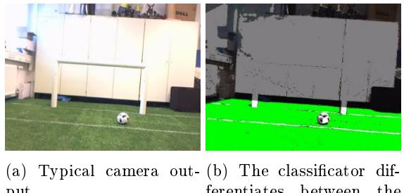
The color analysis is done on a high dimensional cluster classication base. Each cluster is built around sample color points which represent a logical color (green/eld, white/goal, white/eld lines, . . . ). Every logical color is modeled as a Gaussian Mixture Model (GMM), meaning a weighted sum of Gaussian distributions. This method has been known to describe the typical shades and variations of the colors quite well. The model also accounts for the case of multi-colored items like the new ball, since it will just t separate Gaussian components to the dierent colors.
The training of the parameters is done right before the game so the individual lighting and location conditions are considered. The samples needed for the training are created by identifying the objects to be classied in the camera image. To t the model to the samples we calculate the gaussian parameters over the samples. We decide with a threshold if a measurement belongs to a certain gaussian model. This threshold is auto detected. Notably, one YUV value can represent multiple logical colors at the same time using bit masks. A classication result can be seen in Fig. 2.
Fast Partitioning
We are studying a novel algorithm that partitions even high-resoluted images very fast. The algorithm nds interesting regions, so we do not need to waste calculation time on extraneous regions. As a result CPUintense algorithms are deployed only on very few patches of the image.
At rst we compute the integral image. This is the only time we do a calculation that needs O(n) time, with n being the number of image pixels. Each subsequent part of the vision pipeline takes fewer asymptotic time. Integral images have the advantage to allow calculation of the sum of pixel values of any image region in constant time.
The integral image's pixels contain an integer for each color channel with the sum of all pixels of the corresponding channel in the rectangle from the top left to the pixel's coordinates:
$$p_{integral}(x,y) = \sum_{i=0}^{x} \sum_{j=0}^{y} p_{original}(i,j)$$
with pintegral(x, y) as the pixel at x, y in the integral image and poriginal(i, j) as the pixel at i, j in the original yuv image.
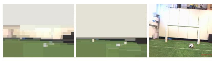
Having the integral image, we build a tree of patches. At the beginning the whole image is one node. Then we check whether there is a signicant edge inside the node. If there is one, we determine whether it is a horizontal or a vertical edge and nd its location. Now the node splits at this edge and two new nodes are created. We recursively apply this algorithm to the remaining nodes. Fig. 3 illustrates the leaves of the trees created for the eld contour extraction respectively for the ball and goal detection.
Field Contour Analysis
The eld contour divides the image in two parts, where the part above the eld contour can be discarded. The lower part contains the visible areas of the pitch and is used for further image processing steps. To nd the eld contour, we apply the partition algorithm to the U and V channel. While building the tree we look whether the newly created nodes contain eld color. If a node does, we raise the eld contour, otherwise we lower it.
Object Extraction
To nd the ball and the goalposts, the tree building is applied to the Y channel. We know that we found a ball or goalpost candidate if a node we created contains the color white.
Goal Extraction
The positions of goalposts in the image are extracted by nding white blobs on the eld and checking whether these blobs touch the eld contour. The base point of a goal post is its position on the eld. We nd the base point by moving the bounding box downwards as long as it contains the color white. Whereas, if it contains the color of the eld, we look for the sharpest edge in this box. The base point is the center of the sharpest edge moved half the post size backwards to match the center of the post.
Ball Extraction
To determine if a white blob actually is a ball or not, our robots utilize a chain of classiers that increase in complexity and accuracy. The chain starts by testing the candidates' size, continues by testing if the top half of the ball candidate is brighter than the bottom half and then tests whether the candidate does not contain to much eld color. Next, we apply a SVM and match against a known color distribution with the KL divergence.
4.4 Modeling
This section describes the modeling approaches used in the software.
Object Modeling
In order to track the ball, obstacles and goals, we employ Kalman lters. The ball model involves the position and velocity. The goals are modeled by four independent posts. This approach allows us to distinguish between the opponent's and our own goal. Obstacles are modeled by a dynamic number of Kalman lters. They also keep track of the team colors.
Motion Editor
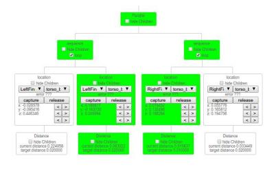
We utilise the general inverse kinematics solver in the motion editor to dene motions. This enables movements to be created easily and eectively. The fundamental idea is to dene tasks in a more abstract way in order to achieve robot independent motions. The goal is to run these tasks on dierent robots that not only dier in link size but also in number and type of joints. A task is mostly dened by two eectors and their position and orientation to each other. The inverse kinematics will compute which actuators are involved. It is possible to dene multiple tasks that can be executed at the same time. Dependencies between the tasks are resolved by prioritization. Sequential tasks are solved by using hierarchical state machines, where each state presents a task.
We use a tree structure to represent these state machines. Each tree node represents a state/task, while the nodes' siblings represent the next state/task. The child of a node can either be a termination criteria of the state, another task with a lower priority or a speed prole with which the parent node is solved.
5 Conclusion
With the outlined improvements to the software of the robots we are looking forward to participate in the RoboCup 2017 competition.
References
- Marc Bestmann, Juliane Bödeker, Fabian Fiedler, Timon Giese, Judith Hartll, Marcel Hellwig, et al. Application from Hamburg Bit-Bots for RoboCup 2016, 2016. Available online at https://www.robocuphumanoid.org/qualification/2016/6c37e719479abe8944d8b3d99f12b66ab370dcca/Hamburg_Bit_Bots_Humanoid_KidSize_2016_TDP.pdf
- Howie M Choset. Principles of robot motion: theory, algorithms, and implementation. MIT press, 2005.
- FUmanoids. FUmanoids Code Releases, 2015. Available online at http://www.fumanoids.de/code/coderelease.
- FUmanoids. FUmanoids Hardware Releases, 2015. Available online at http://www.fumanoids.de/hardware.
- Simon Gene Gottlieb. ModuleChain, 2016. Available online at https://github.com/SGSSGene/ModuleChain.
- von Seelen Kalinke. Kullback-Leibler Distanz als Maÿ zur Erkennung nicht rigider Objekte. In Erwin Paulus and Friedrich M. Wahl, editors, Mustererkennung 1997, Informatik aktuell. Springer Berlin Heidelberg, 1997.
- S. Thrun, W. Burgard, and D. Fox. Probabilistic Robotics. Intelligent robotics and autonomous agents series. Mit Press, 2005.