ITAndroids Humanoid Team Description Paper for RoboCup 2017
Davi Herculano, Daniela Vacarini, Igor Silva, Leonardo Cunha, Luis Aguiar, Marcos Maximo, Miguel Ângelo, Samuel Pinto
Autonomous Computational Systems Lab (LAB-SCA); Aeronautics Institute of Technology (ITA); São José dos Campos, São Paulo, Brazil
Abstract ITAndroids is a robotics competition group associated to the Autonomous Computational Systems Lab (LAB-SCA) at Aeronautics Institute of Technology (ITA). ITAndroids is a strong team in Latin America, especially in the simulation leagues. Our Humanoid KidSize team has worked with low cost humanoids robots since 2013. However, the group recently received a financial aid from ITA to acquire a Robotis OP2 robot and material to build 4 more robots. This paper describes our recent efforts, including the software development and our new robot design based on the DARwIn-OP project.
1 Introduction
ITAndroids is a robotics research group at Aeronautics Institute of Technology. As required by a complete endeavor in robotics, the group is multidisciplinary and contains about 40 students from different undergraduate engineering courses. In the last 5 years, we have achieved good results in competitions, especially in Latin America. In RoboCup 2D Soccer Simulation, we have placed in the range 10th-12th in the 2012, 2013, 2014, and 2016 editions of RoboCup. In 3D Soccer Simulation, we have placed in top 12 in the 2013, 2014 and 2015 competitions, while placing 6th in 2016. In the Latin American Robotics Competition (LARC), we have been consistently placing in top 2 in both Soccer 2D and 3D during the last 5 years.
Regarding our humanoid team, we have been struggling with low cost robots since 2013, thus making it very hard to attain good results in competitions or even qualify for RoboCup. Still, we achieved the 3rd place in LARC 2014 in the KidSize competition. In 2016, we have received a Robotis OP2 robot and enough material to build other 4 robots.
Backed by the code developed for other leagues, especially for RoboCup 3D Soccer Simulation, we have been quickly evolving since the arrival of our Robotis OP2 robot. Moreover, we have benefit from the 2012 UT Austin Villa code release for the Standard Platform League (SPL).
This paper presents our recent efforts in developing a humanoid robot team to compete in RoboCup Humanoid KidSize. The rest of the paper is organized as follows: Sec. 2 introduces the robot hardware. Sec. 3 presents our software architecture and tools. Sec. 4 explains our computer vision techniques. Sec. 5 shows our state estimation approach. Sec. 6 discuss our motion control algorithms. Finally, Sec. 7 concludes and shares our expectations for the future.
2 Hardware
In 2016, we have acquired sufficient material to build 4 humanoids robots, including 80 MX-28AT servomotors. Thus, we are designing a new humanoid robot based on the DARwIn-OP. We named our robot project Chape as a tribute to the Chapecoense team, a Brazilian soccer team that lost most of its members in a flight accident. The electronics and mechanics are being developed in order to generate a modular architecture that allows hardware upgrades. Another important requirement is to facilitate the maintenance tasks, avoiding a large disassembly of the robot when maintenance is needed.
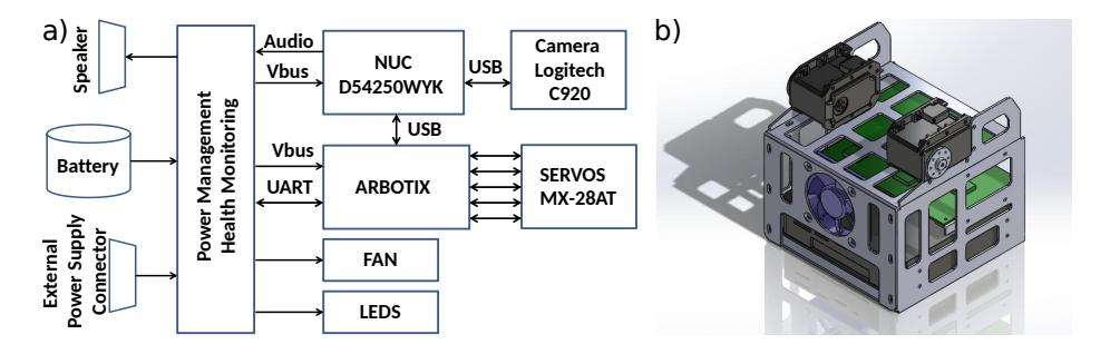
As shown in Fig. 1(a), the electronics is composed by a High Performance Processing Unit (HPPU), a Low Performance Unit (LPPU), a Power Management and Health Monitoring board (PMHM), a Camera, a Battery and Servos. The HPPU is implemented with a NUC D54250WYK and will concentrate the high demanding computation tasks. The LPPU, implemented with an Arbotix Pro, is responsible for interfacing the HPPU with the servos and the IMU. Moreover, it logs the built-in tests and power status generated by the PMHM board.
The PMHM is entirely developed by the ITAndroids team. This board has the following functions: a) manage the power supply, including automatic switching between the battery and an external power supply; b) treat abnormal events such as sudden overcurrents and short circuits; c) autonomously start self protection routines in case of internal overheating; d) amplify the audio signals sent to the speakers; e) perform hardware built-in tests; f) control the indicative LEDS in order to communicate status and alarms.
Regarding Mechanics, we will adapt the DARwIn-OP's head and chest in order to accommodate our own electronics, while keeping the legs unchanged and making small modifications to the arms to make them longer. Fig. 1(b) shows a CAD model of our new chest. We are building 4 humanoid robots, besides the Robotis OP2 robot that we already have, to compose a full KidSize team.
3 Software Architecture and Tools
We use a module-based layered approach for code architecture, which has proven to have several advantages in our experience. It encourages better code organization, allows for a high degree of code reuse and flexibility, and permits sharing most of the code between the real robot and a simulated one.
We use the same overall code structure that was developed for our ITAndroids Soccer 3D code. This structure is divided into 6 main layers:
- Communication: communicates with the robot hardware (actuators, camera, subcontroller etc.) or with a simulator.
- Perception: transforms data received from the Communication layer into high level data structures used by the higher layers.
- Modeling: models the world and agent states. This layer contains the algorithms for computer vision and robot localization.
- Decision Making: implements the high level strategy used for robot soccer. This layer is organized as a tree-based structure of behaviors
- Control: computes actuators commands needed to execute the requests from Decision Making. For instance, a walk request is converted into joints positions through a control algorithm.
- Action: translates the commands generated in the Control layer into an appropriate format to be sent to the actuators by the Communication layer.
The agent is implemented in C++. The main third-party libraries used are OpenCV (Computer Vision) [3], Eigen (Linear Algebra) [5], and Boost (general purpose) [1]. Despite our core agent code does not use it, we heavily rely on the Robot Operating System (ROS) framework [12] and its related tools for testing and debugging purposes.
A simulation model for the DARwIn-OP robot has already been developed for Gazebo [4]. However, this model has many mechanical details, making it unnecessarily heavy and unsuitable for multiple robots simulation. Therefore, we have used this simulation model mainly for prototyping motion algorithms. We also use ROS to communicate with Gazebo.
In our agent, we have two threads running simultaneously. The cognition thread runs at the sample rate of the camera image capture (30 Hz) and is responsible for world modeling and decision making. The motion thread runs at a much higher rate (currently, 125 Hz) and deals with motion control.
4 Computer Vision
Our vision system uses a base code for the Standard Platform League made publicly available by the Austin Villa team in 2012 [2]. The main differences between the released code and ours are related to the detection of the white ball, the white goalposts and general bug fixes.
The first step in the vision pipeline is the color segmentation, which is responsible for classifying each image pixel as white, green, blue etc., based on a color table. To generate the color table, we manually classify pixels in an image and then train a Neural Network classifier, using the MATLAB Pattern Recognition App from the Neural Network Toolbox [14].
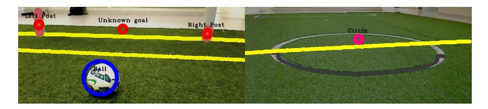
The next step involves analyzing the segmented image in order to detect objects. First, an horizon line is generated based on the 3D camera position and its intrisic parameters. This line is used to filter "floating" objects, which are above the horizon line. Then, blobs are formed, which are collections of contiguous pixels of the same color. The white blobs are used to generate lines, which are classified into goalposts, curves or straight lines. The penalty cross is detected by analyzing white blobs surrounded by mostly green pixels. The detections is illustrated in Fig. 2.
For the white ball detection, our team used the following approach, illustrated in Fig. 3: initially, color classification is performed to identify white pixels. However, the classified image does not present a single solid circle, as desired: the main one is filled with holes, due to the ball texture. Also, there are many white pixels outside the main ball cluttering the image, since there are white pixels in the grass. In order to overcome these issues, mathematical morphology operations were used, namely closing (to mitigate the white pixels in the grass) followed by opening, which leads to a solid circle without holes inside it.
Then, after the morphological operation, Hough Circle Transform is used on the gradient of the image. Our team used the houghCircles function implemented in OpenCV [3], which does both the Hough Transform and the gradient image computation. However, many false ball detections were present, since there may be other white objects in the robot's field of view. Thus, to eliminate them, filtering is performed. Thresholds were set to establish minimum and maximum radius, and a minimum density of white pixels within the detected circle. Besides that, if a ball is detected beyond the horizon line, it is discarded.
However, in order to eliminate the vast majority of false positives, our approach sometimes produces false negatives. This issue was overcome with a tracking algorithm, as described in Subsec. 5.1.
The computer vision algorithms localize the objects in the 2D matrix of pixels. However, for localization and tracking purposes, the 3D positions of the objects are needed. Given the 2D point in the image, its x and y 3D coordinates can be estimated if we constraint that z=0, i.e. the object is on the ground. To compute the camera pose in the robot's frame, we use Forward Kinematics. This coordinate transform process is described with more details in [7].

5.1 Ball Tracking
Since computer vision is not fully reliable, a Kalman Filter based algorithm was used to track the ball and reduce the estimation error. In particular, when a false negative happens, we still need to keep tracking of the ball. In our approach, the state is composed by the ball's positions and linear velocities in the robot's frame, $\mathbf{x}k^r = [x_k^r \ y_k^r \ v{x,k}^r \ v_{y,k}^r]^T$. Moreover, the observation model is composed by its 2D position $\mathbf{z}k^r = [x_k^r \ y_k^r]^T$, as estimated by the computer vision algorithm. The motion model follows in Eq. (1), as can be seen, linear accelerations are modeled as the Gaussian noises $w{a,x}$ and $w_{a,y}$. Note that, since the tracking is done on the robot's frame, the robot odometry $\Delta \mathbf{d}_k^r = [\Delta x_k^r \ \Delta y_k^r \ \Delta \psi_k^r]^T$ needs to be taken into account when updating the filter.
$$\mathbf{x}{k}^{r} = \begin{bmatrix} \cos(\Delta\psi{k}^{r}) & \sin(\Delta\psi_{k}^{r}) & T & 0\ -\sin(\Delta\psi_{k}^{r}) & \cos(\Delta\psi_{k}^{r}) & 0 & T\ 0 & 0 & \cos(\Delta\psi_{k}^{r}) & \sin(\Delta\psi_{k}^{r})\ 0 & 0 & -\sin(\Delta\psi_{k}^{r}) & \cos(\Delta\psi_{k}^{r}) \end{bmatrix} \mathbf{x}{k-1}^{r} - \begin{bmatrix} \Delta x{k}^{r}\ \Delta y_{k}^{r}\ 0\ 0 \end{bmatrix} + \begin{bmatrix} \frac{T^{2}}{2} & 0\ 0 & \frac{T^{2}}{2}\ T & 0\ 0 & T \end{bmatrix} \begin{bmatrix} w_{a,x}\ w_{a,y} \end{bmatrix}$$ (1)
5.2 Localization
In order to solve the global localization problem, we use an extended Monte Carlo Localization technique, described in [13] and [11]. In this MCL adaptation, it is possible to solve the kidnapping problem using sensor reset, which occurs based on the likelihood of the observation in a given moment.
In this localization problem, the discrete process state $\mathbf{x}_k$ is composed by the robot's 2D position and orientation in the field, $\mathbf{x}_k = [x_k \ y_k \ \psi_k]^T$. Moreover, the robot displacement is given (in the robot's frame) by $\Delta \mathbf{d}_k^r = [\Delta x_k^r \ \Delta y_k^r \ \Delta \psi_k^r]^T$, where the odometric information is given by the walking engine.
Composing the observation model, we have distances to observed field features, such as "L's", "T's", goal posts, crosses and the field center. Besides, it includes the observation of each line's intersection points with the limits of the robot's vision. Calling all that seen points landmarks, we compute the observation probability as described in Eq. (2).
$$p(\mathbf{Z}_k|\mathbf{x}_k^{[m]}) = \prod_j \exp\left[-\frac{(d_j - \hat{d}_j^{[m]})^2}{2\sigma_d^2}\right] \exp\left[-\frac{(\psi_j - \hat{\psi}j^{[m]})^2}{2\sigma\psi^2}\right]$$ (2)
In this model, $d_j$ and $\psi_j$ are respectively the measured horizontal distance and horizontal angle between the robot and the j-th landmark, and $\hat{d}_j^{[m]}$ and $\hat{\psi}_j^{[m]}$ are respectively the expected horizontal distance and horizontal angle between the j-th landmark and the robot in the m-th particle position.
To face the landmark ambiguity problem, we adopt an approach based on the maximum observation likelihood, the same strategy we use for field lines observation in Soccer 3D. This approach is described with more details in [11].
6 Motion Control
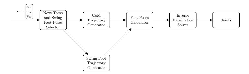
For walking, we use the ZMP-based omnidirectional walking engine described in [8]. In general terms, it follows the flux presented in Fig. 4. The input to the algorithm is the desired velocity $\mathbf{v} = [v_x, v_y, v_\psi]^T$ with respect to the robot's local coordinate system. At the beginning of a new step, poses for the torso and the swing foot are selected for achieving the expected displacement at the end of the step. So, a trajectory for the center of mass (CoM) to follow a reference Zero Moment Point (ZMP) trajectory is computed. The trajectory of the swing foot is obtained by interpolating between the initial and final poses of this foot. Finally, joints angles are calculated through Inverse Kinematics (IK) considering the poses of the support and swing feet. Note that the module "Next Torso and Swing Poses Selector" is called once for step, while the others are executed at the update rate of the joints.
Our step planner selects torso and feet poses to make the robot follows an omnidirectional model while respecting self-collision and leg reachability constraints. To reason about the robot dynamics, we approximate it using the 3D Linear Inverted Pendulum Model (3D-LIPM) [6]:
$$\mathbf{x}{ZMP} = \mathbf{x}{CoM} - \frac{z_{CoM}}{g} \ddot{\mathbf{x}}_{CoM} \tag{3}$$
where $\mathbf{x}{ZMP} = [x{ZMP}, y_{ZMP}]^T$ is the ZMP position, $\mathbf{x}{CoM} = [x{CoM}, y_{CoM}]^T$ is the CoM position, $z_{CoM}$ is the CoM height, and g is the acceleration of gravity. The ZMP is kept at the center of the support foot during single support and moves from the current support foot to the next one during double support. We also use the torso's angular velocities measured by the gyrometer to stabilize the walk. This feedback strategy has proven quite effective, especially when walking on artificial grass.
For kicking, we first considered that it is a movement where the biped starts in a stand position, kicks the ball and returns to the same stand position. Given this description, we divided the motion into 4 phases: a) the ZMP is moved to the center of the support foot; b) the robot kicks the ball; c) the kicking foot is placed back on the ground; d) the ZMP goes back to the center of the torso. To balance the biped during kicking, we employ the same ZMP-based algorithm used for walking. For the getting up movements, we are using the original Robotis OP2 keyframes with slight modifications to make them work on artificial grass. For more information about our keyframe movements framework, please refer to [10].
7 Conclusions and Future Work
This paper presented the recent efforts of ITAndroids group in RoboCup Humanoid KidSize. This year, we have started a new humanoid robot design based on the DARwIn-OP. We intend to build 4 new robots based on this design to participate with a full robot team in the competition. Besides, we want to share this project with the community when it is ready, since many teams complain about the difficulty of exactly reproducing the DARwIn-OP robot, given that some of its electronic components are hard to obtain.
We have also developed our own base code, inspired by our Soccer 3D team code. Most of the software components are done and we are now finalizing the system integration. Nevertheless, our software still lacks the robustness and performance needed for being strongly competitive in the current level of the competition. Thus, our development efforts will be focused on improving the code behavior in the real robots. We also expect to implement our new walking algorithm [9].
Acknowledgment
We thank our sponsors ITAEx, Micropress, Poliedro, Poupex, and Radix. We also acknowledge Mathworks (MATLAB), Atlassian (Bitbucket) and JetBrains (CLion) for providing access to high quality software through academic licenses.
References
- BOOST C++ Libraries. http://www.boost.org.
- Samuel Barrett, Katie Genter, Yuchen He, Todd Hester, Piyush Khandelwal, Jacob Menashe, and Peter Stone. The 2012 UT Austin Villa code release. In RoboCup-2013: Robot Soccer World Cup XVII. Springer Verlag, 2013.
- G. Bradski. Dr. Dobb's Journal of Software Tools, 2000.
- Dr. Philippe Capdepuy. DARwIn-OP Gazebo Simulation Model, 2016.
- Gaël Guennebaud, Benoît Jacob, et al. Eigen v3. http://eigen.tuxfamily.org, 2010.
- S. Kajita, F. Kanehiro, K. Kaneko, K. Yokoi, and H. Hirukawa. The 3D Linear Inverted Pendulum Mode: A Simple Modeling for a Biped Walking Pattern Generation. In Proceedings of the 2001 IEEE/RSJ International Conference on Intelligent Robots and Systems, October 2001.
- Yi Ma, Stefano Soatto, Jana Kosecka, and S Shankar Sastry. An invitation to 3-d vision: from images to geometric models, volume 26. Springer Science & Business Media, 2012.
- Marcos R. O. A. Maximo. Omnidirectional ZMP-Based Walking for a Humanoid Robot. Master's thesis, Aeronautics Institute of Technology, 2015.
- Marcos R. O. A. Maximo, Carlos H. C. Ribeiro, and Rubens J. M. Afonso. Mixed-Integer Programming for Automatic Walking Step Duration. In Proceedings of the 2016 IEEE/RSJ International Conference on Intelligent Robots and Systems (IROS), 2016.
- Francisco Muniz, Marcos Maximo, and Carlos Ribeiro. Keyframe Movement Optimization for Simulated Humanoid Robot using a Parallel Optimization Framework. In: Latin American Robotics Symposium. In Proceedings of the the 2016 Latin American Robotics Symposium (LARS), October 2016.
- Alexandre Muzio, Luis Aguiar, Marcos Maximo, and Samuel Pinto. Monte Carlo Localization with Field Lines Observations for Simulated Humanoid Robotic Soccer. In: Latin American Robotics Symposium. In Proceedings of the the 2016 Latin American Robotics Symposium (LARS), October 2016.
- Morgan Quigley, Ken Conley, Brian P. Gerkey, Josh Faust, Tully Foote, Jeremy Leibs, Rob Wheeler, and Andrew Y. Ng. Ros: an open-source robot operating system. In ICRA Workshop on Open Source Software, 2009.
- W. Burgard S. Thrun and D. Fox. Probabilistic Robotics. MIT Press, 2005.
- Inc The Mathworks. MATLAB and Pattern Recognition Toolbox, 2016.