Team RoBIU
TAMAR VICLIZKI, SHAY YASHAR, EVYATAR NEZER, LIRAZ BENBENISHTI, DORON NAHARI, ALON MAR, CHAIM
Bar-Ilan University, Faculty of Engineering
Abstract Team RoBIU was founded in 2010. The team consists of undergraduate students from Bar-Ilan University, Faculty of Engineering. This paper presents an overview description ofthe hardware and software layer of the kidsize humanoid robots of RoBIU team. The following documents describe the robot's hardware specifications and a high level description of the various software algorithms, including real-time image processing, stabilization, sensors and camera based localization, debug features, robot agents inter-communication and high-level behaviours implementation.
1 Introduction
This paper describes the RoboCup Kid Size League team RoBIU from Bar-Ilan University. The team was founded in 2010 and this is the 6th yearthat the team is applying for participation in the KSL league. Each year the team is assembled with new undergraduate senior year computer engineering students, as a part of theirfinal year project underthe supervision of Dr. Eli Kolberg and the mentors Dr. Beni Abramov and Mr. Rafi Amsalem. One purpose of the Robocup KSL project is to let the students experience a large-scale projects, which incorporates many challenges, such as strategic orientation, coping with deadlines, mediating between target groups and managing the development of software-intensive systems.
RoboCup2018 wouldbe a great setting to study our enhancedsoftware and team performance.
Prior Performance In RoboCup Competitions
2014 - 2 nd Round Robin.
2013 - 1 st Round Robin.
2012 - Quarter finals.
Enhancements of the Robot's Compared to the Previous Year
In order to improve our robot's abilities, we will set a wider angle for head tilt such that the ball can be seen even if it just touch the feet.
In addition, the new robot is higher, which gives it the ability to look farther in the field. It also has cleats for better grip when moving in the field.
The software was developed by the current team members, based on last year program. The program includes new algorithms with better performance in terms of runtime, accuracy and robustness. Moreover, we improved the robot's scanning and following algorithms.
We added features of white line, corners, and junctions identification in addition to distance to objects measurements.
These improvements do not use GPS or local- detection systems. They are based on gyroscope and camera that feed the input to localization algorithms.
In addition, the robot's code is a multi-threading code in order to enhance the operation of the different systems that work in parallel.
2 Hardware
The robot's hardware - Motors, Sensors and Specifications - is presented in the "RobotSpecifications" document.
3 Software
Our robot's software integrates several components that combine a real time soccer playing robot. In order to do so, we designed a software that combines all the necessary functionalities into one multi-threaded program.
Our software, from design to implementation, was developed by teamRoBIU without anyuseof software fromother teams.
3.1 Multi-Threading
Multi-threaded environment let us deal with the robot's various moduls (such as brain, vision, localization, etc.) in order to be more efficient. We preferto use multi-threading over multiprocessing so we could use the same memory space for all our software components, and in order to save the context-switch time. Our software consists of 4 main threads - Brain, Vision,Localization and Communication.
3.2 Artificial Intelligence
Artificial intelligence - AKA Brain - is the main component in our design. It is in charge of taking all important inputs from other modules, processing, understanding and deciding the next move. The brain implementation is based on a FSM (finite state machine), which computes the next state according to the current state and the various updated inputs (vision, localization, etc.).
We started by writing a simple FSM which knows how to find the ball and kick to the opponent's goal. Afterwards we gradually considered more and more factors such as Localization properties and communication between robots, in order to make the robot more intelligent.
3.3 Vision
The Vision module is responsible for image processing. The main goal is to detect meaningful objects - ball, goal and white lines. (This year we will deal with corners as well)
The implementation uses some functions from the OpenCV image processing library [2].
Calibration Tool
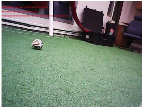
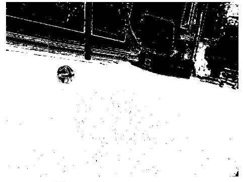
Our design contains a separate tool that adjust ourimage-processing to the current environment colors. The tool "teaches" the robot how to define the green color spectrum and the white spectrum. The tool shows the user 2 images - the original image and an "only green"/"only white" image. The user clicks on the green pixels in the original image and the tool colors only thesepixels inwhite inthe "onlygreen"/"onlywhite" image, as canbe seen in Fig. 1.
Common Image Processing Techniques
HSV - We use the HSV (hue,saturation & value) image format[3] which is more adequate here than RGB format. RGB components of an object's color in a digital image are correlated to the amount of light hitting the object, and therefore with each other. Thus, image descriptions in terms of RGB components make object discrimination difficult. Instead, descriptions in terms of HSV are far more relevant.
Dynamic Threshold - Almost every image processing in our code starts with an "image segmentation". This is done in a very simple way,using the threshold method. The threshold uses the values that were calibrated with our calibration tool. By doing so, the threshold varies with every calibration, making it adaptive to a variety of lighting conditions, grass color, etc.
Erosion & Dilation After thresholding we use Erosion & Dilation to "fill holes" in the given B&W image. Erosion is done by applying a filter on the image that changes pixel color to white iff all the pixels that surrounds it are white. Dilation does the same action for black pixels. Combining these filters gives us the ability to "fill holes" and more.
Various algorithms have been tested regarding ball, goal and white-lines detection. Ultimately we've chosen the most efficient one in terms of fast computations and accuracy as described below.
We used Canny Algorithm(that use Sobel operator) in order to find edges in grayscale pictures. By using Canny algorithm we had to take care about:
- -low error rate
- -edge points should be localized
- -single edge point response
Ball Detection
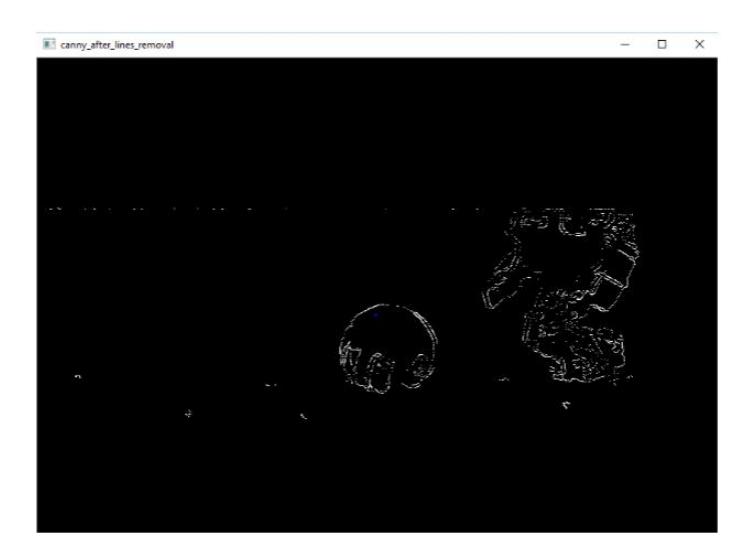
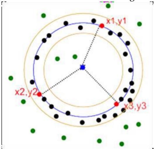
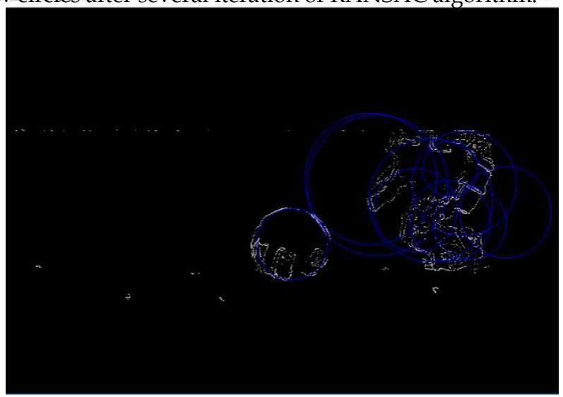
For ball identification we use HLT (Hough Line Transform) to find and erase lines. Here line deletion allows for decreasing software complexity. Since most of the contours in the image except the ball are made of straight lines, it helps to reduce the edges that are not a part of the ball contour. This method is effective only for RoboCup due to the unique object shape.
Distance to ball calculation
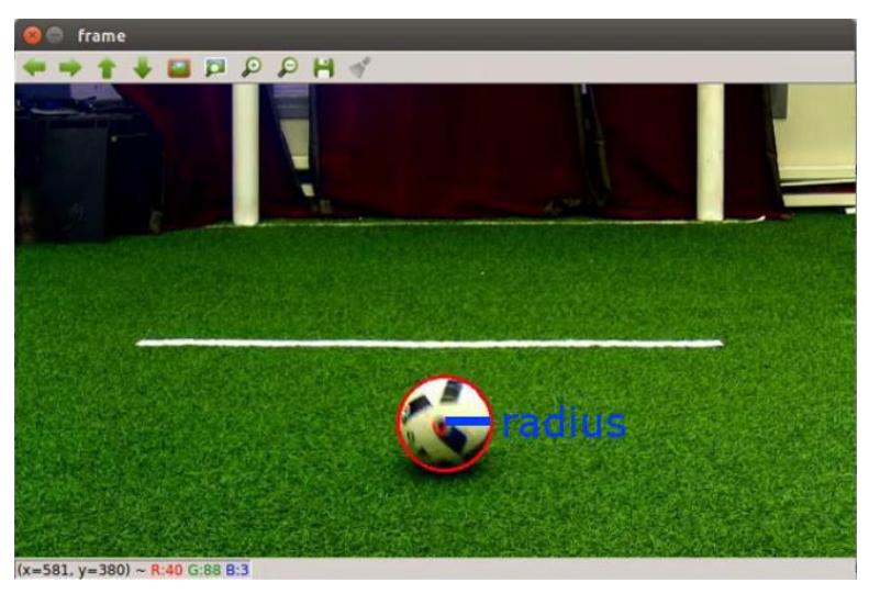
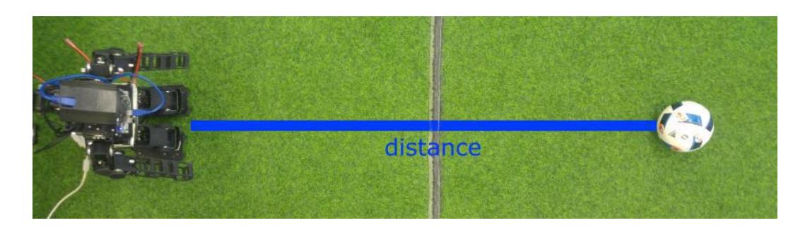
After considering several methods like triangulation and linear approximated look-up table we decided to use the linear regression tool. 30 samples are used for building a 3rd degree polynomial function that produces the distance as a function of the ball radius.
Scan and follow the ball
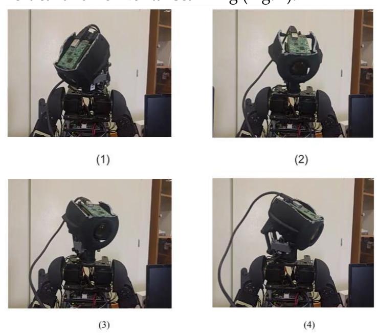
We used Gazebo simulator in order to detect the optimum scan method. It lead us to a sine scanning. It is performed by synchronizing 2 head motors for vertical and horizontal scanning (Fig. 7).
Goal Detection
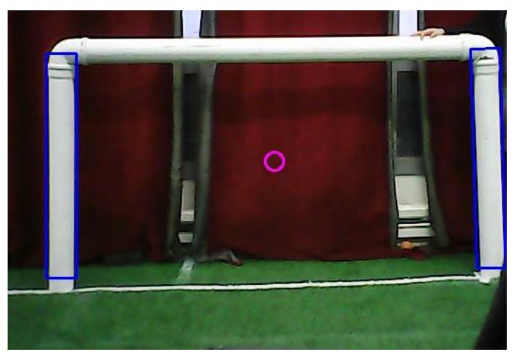
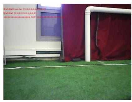
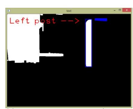
The goal detection is based on finding objects, which are suspected to be the goal's posts, in the input image. Then, the algorithm selects the most relevant ones to be the posts (Fig. 8). If only one object was found, the algorithm will determine which one of the two posts the robot sees.
Object is suspected as a post if it satisfies the following terms:
- White: First,weuseasimplethresholdfunctionontheHSVtransform of the given image (White is easy to recognize in the HSV transform image). We get a B&W image, in which only white objects are white.
- Vertical: Weperforma vertical erosion algorithm onthe givenimage to remove any horizontal white objects from the image. Only vertical white objects are left.
- Rectangle-shaped: Weuse OpenCVs minAreaRect to surround all these objects with minimum area rectangles. We check the ratio betweentheoutputrectangleandthewhite-objectarea,andweeliminate any rectangle that does not satisfy the threshold ratio.
- Straight-angled: From the robot's eyes, the posts are orthogonal to the fields plane. We check that the rectangles angle is close to zero.
- Inter-edge ratio: The post's shape is characterized by long vertical edge anda shorthorizontal edge. Weeliminateanyrectangle thatdoes not meet thischaracteristic.
Full goal detection: We take the 2 largest candidates to be the posts:
Line Detection
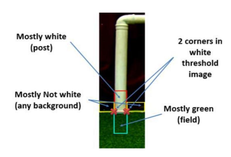
For line detection the algorithm uses 2 matrices: one for detecting the field's area (grass), and one for holding the potential lines (the area that is colored white).
Then, the algorithm extracts the boundaries of the field from the first matrix, and creates a new matrix that will help to determine which parts are white according to the observations and insert black value to the remaining cells.
Next step is performing an AND operation between the white matrix and the boundaries matrix. Then, in the last step, HoughLines transform is used to detect the lines.
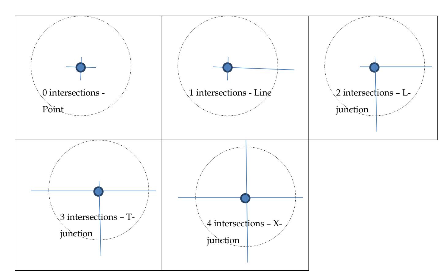
Corner Detection
L junction detection:
In Cartesian coordinate system a straight line can be represented by the equation:
$$y = mx + n$$
Where m is the line slope and n is the Y Intercept (where the line crosses the Y axis). M and n are constant and (, ) represents an arbitrary point of the line (line 1).
It is possible to convert to polar coordinate system such that (, ) coordinates can be converted into (, ) coordinates.
In order to demonstrate the conversion, a line that pass through the axis and is perpendicular to the first line will be added (line 2). The equation of this line is:
$$y = -\frac{1}{m}x$$
We choose to be the angle between the perpendicular line and the positive x-axis. is defined as the distance between the straight line and the origin (which is exactly the length of the perpendicular line between the origin and the intersection with the straight line). It is shown in the following drawing:
It can be shown that:
$$\theta = \arctan\left(-\frac{1}{m}\right) \to m = -\frac{\cos(\theta)}{\sin(\theta)}$$
and therefore: = + → = − cos() sin() + → () + () = ()
since = ():
$$\rho(\theta) = ysin(\theta) + xcos(\theta)$$
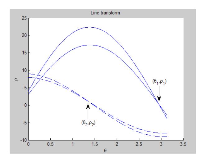
Running through 0 ≤ ≤ 2 will produce the curve of ().
(Fig. 10)
It can be done for all the detected lines. To every (, ) there will be a joint point (1, 1). For a different straight line that cross the same (, ) point, there will be a different polar coordinates joint point (2, 2). (Fig. 11)
We know that the lines are vertical <=> 2 = |(θ1 ) − (θ2 )|

3.4 Localization
Localization of the robot is one of the main features for its successful functionality. Itmeans thatthe robotunderstands anddecideswhere itis located and it consequences.
Theproblems relatedtothe localizationalgorithms include improper image data, symmetric playing field - e.g. in case the robot sees only a white line, it won't be able to decide which line in which side of the court it is, if localization is not used.
In addition, localization is required for planning the robot's next move. According to its location, the robot can determine what should be its next move; whether to go to ball, come back to help the defense or move to the center of the goal (in case it is a goalkeeper).
There are various and different ways to implement localization. Most of themare savingandusingformerdataandcurrent samplinginordertoconclude the current localization. We decided to use "Particle Filter " in our project, which can help us to resolve the main following issues:
Position tracking - In this scenario, we want the robot to find its location, as the initial location ofthe robot is known, as well as its control data since it started. The Particle Filter can solve this problem simply, by only changing the initialdistribution.
Initial localization - We want to be able to find the robot position in the field when there is no an initial position. We can use a uniform distribution as a starting point andrely onthe "Particle Filter" to converge given enough parameters.
Kidnappedrobotproblem-Thisproblemis thehardest. Inthis scenario, the robot can be 'teleported' at any time (e.g. the robot being moved by the referee) and the robot still need to be able to find its position after few iterations ofthe filter. Tosolve this scenario weuse theMonte-CarloParticle Filter.
As an input for the localization, we mainly use vision along with the obstacles the robot identified so far. In addition, we take an advantage of the Gyro,whichenablesus toconfigure inwhichdirections the robotturnedand walked.
Parenthetically, we should take into consideration that the data on which the localization algorithm relies, namely Gyro and image processing, is not clean as it contains sample noise and other erroneous data. Consequently, theresolutionoftherobot's locationwillneedtobea"wisedecision",relying on a high probability. Another parameter we took into consideration is the type of environment. In a static environment, the one of which the Particle filter was developed for, the only changing variable is the robot's position. However, in our case, there are other moving objects (e.g. other robots). Despite ofthis fact, we can still consider our environment static since we can detect the field (a static variable) even though there are objects on itusing image processing. Thus, we can still use the Particle Filter.
4 Conclusions
In our document we've introduced the hardware structure and software design of our robots. Although it will be the 6th year that Bar-Ilan University will participate in the competition, all the team members have changed (except of the mentors), so this will be ourfirst chance to take part in RoboCup. We look forward to participate in the RoboCup competition this year, and aredeterminedtoplayasworthycompetitors.
References
[1] Robotis Product Information, http://www.robotis.com. [2] G. Bradski and A. Kaehler, Learning OpenCV: Computer Vision with the OpenCV Library, O'Reilly Media, October, 2008. [3] R.GonzalezandR.Woods,Digital ImageProcessing,ThirdEdition, PearsonEducation, 2008. [4] S. Thrun, W. Bugard and D. Fox, Probabilistic Robotics. MIT Press, 2005.