UTRA Team Description Paper RoboCup 2018 Humanoid League (KidSize)
Jason Wang, Shahryar Rajabzadeh, Tyler Gamvrelis, Lukas Zhornyak, Nam Nguyen, Newton Xu, Mariko Tatsumi, Arnav Goel, Walton Wang, Justin Yuan, Steven Liu, Yuchen Wu, Gokul Dharan, Izaak Niksan, Jenny Yang, Xu Xiaoxue, Omer Faruque, Samee Mahbub, Jeffrey Qiu, Gallop Fan, Ganeshan Sivakumaran, Kyle Kim, Daniel Campoverde, Robin lin, Steven Lee
University of Toronto, Toronto ON M5S1A1, Canada
http://www.utra.ca/teams/soccer/
Abstract This document presents the robot ("Béz") that University of Toronto Robotics Association (UTRA) has submitted for consideration in the RoboCup 2018 Humanoid League (KidSize class). The mechanical, control, electrical/embedded, and software subsystems are described in detail as well as the team's research interests.
Keywords: RoboCup 2018, bipedal robot, mechatronics, mobile robotics, embedded systems, inverse kinematics, RTOS, ROS, computer vision, localization, image processing, path planning
1 Introduction
The University of Toronto Robotics Association (UTRA) team consists of undergraduate students from the Electrical, Computer, Robotics and Mechanical Engineering departments at the University of Toronto, Canada. The team was formed in the summer of 2017 with the goal of being the first team to participate in RoboCup that is composed solely of undergraduate students. The team members are engineering students in years 1 through 3 who are distributed among four subsystems: mechanical, control, electrical/embedded and software. UTRA was able to design, prototype, and construct a walking humanoid robot in 8 months. The team plans to improve on the current design in its future iterations by designing 3D printed parts and making custom servo motors.
2 System Overview
There are two control units on the robot. One is a Jetson TX2 module from NVIDIA that handles the high-level and computationally-intensive algorithms such as computer vision, localization, and artificial intelligence (AI). The other control unit is a STMicroelectronics ARM-based 32-bit microcontroller, which handles the real-time control algorithms for controlling the actuators and acquiring motional data. A communication link between the two units uses publishersubscriber messaging to transmit high-level commands (such as moving to certain coordinates on the field) and relay state information. This approach of using two controllers in an asynchronous manner disentangles the control systems from AI and computer vision, thereby reducing the probability of computational bottlenecks and improving reliability.
3 Mechanical Subsystem
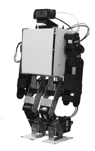
UTRAs robot is inspired by the Darwin-OP open source humanoid research robot [1]. It stands 45 cm tall and weighs 2.4 kg. The robot is actuated by 16 Dynamixel AX-12A servos. There are six motors in each leg and two motors in each arm. All the electronics are embedded inside the box-shaped body. A camera is fixed to the top of the body and does not rotate. The robot was constructed out of aluminum sheets, which were cut and bent by hand according to CAD designs. The arms are an exception as they are 3D printed. The robot is depicted in Fig. 1.
4 Control Subsystem
Placeholder for section 4.
4.1 Poses
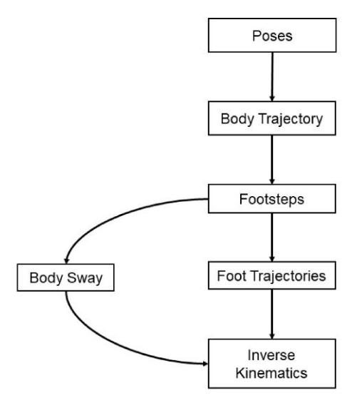
The state of the body is defined by a pose, which consists of the following properties with respect to an absolute coordinate system (e.g. the playing field): the x-, y-, z-coordinates, the angle, and the speed of the robot. The x- and y- coordinates refer to the position on the field while the z-coordinate refers to the lower hip of the robot. The angle references the direction the robot is facing with respect to the reference x-axis.
4.2 Body Trajectories
Given two poses – an initial and desired pose of the body – a body trajectory is generated by a 3rd order Bézier curve. This is the path that the body will take. Many trajectories in this design utilize Bézier curves since their coefficients can be judiciously chosen to control the values and derivatives at the end points.
4.3 Footstep Planning
The positions of the footsteps on the x-y plane which allow the robot to follow the given body trajectory are iteratively generated. Each footstep is given a constant airtime and the speed of the robot is controlled by varying the step length. Deviations by the footstep from the body trajectory are determined through the curvature of the path.
4.4 Foot Trajectories
After obtaining the footsteps, the foot trajectories are then calculated. First, the relative position of the next footstep from the previous one is found at the time of touchdown by subtracting the absolute coordinates of the body and the foot. To find the joint parameters that satisfy the current foot coordinate, inverse kinematics is employed. This generates a family of solutions, from which the solution which admits the smallest Euclidean distance from the previous iteration is chosen. After finding the relative position of the current footstep at take-off, a 4th order Bézier curve (4th order since there are 4 boundary conditions, the positions and the velocities at the end points as well as the height at the half point) is fit between these points. This is for the swing phase.
Similarly for the stance phase, the absolute coordinate for the same foot is used. A 4th order Bézier curve is fit between the corresponding points.
4.5 Body Sway
To deal with the body sway of the robot when walking, an exponential smoothing filter is used. This way, when the body attempts to center itself under the foot, the trajectory is less abrupt and the transition is smoother.
4.6 Specific Actions
The specific actions performed by the robot are mainly kicking and getting up from a prone or supine position. These actions are performed by discretizing the action into finitely many joint angles states separated by a specified duration of time. These states are then interpolated by fitting 3rd order Bézier curves (3rd order since there are four boundary conditions: the positions and the velocities at the endpoints) between the states. To simplify calculations it was also noted that every state in the continuous trajectory was statically stable, so transition between the states was stable even at low speeds.
5 Electrical/Embedded Subsystem
Placeholder for section 5.
5.1 Jetson TX2 Embedded Computer
The Single Board Computer (SBC) hosts an NVIDIA System on a Chip that runs Ubuntu 16.04 on its quad-core ARM Cortex-A57 and is also capable of high performance parallelized computing through the 256 Pascal GPU cores. The TX2 module is used with the Orbitty Carrier board from Connect Tech Inc. to make its I/O accessible. The TX2 is responsible for running the high-level control and strategy software as well as computer vision algorithms; thus, the carrier board is connected to a Logitech C920 HD camera for image acquisition. The TX2 module also dedicates a USB port for communication with a ST microcontroller, which handles the real-time control of the peripherals on the robot.
5.2 Microcontroller
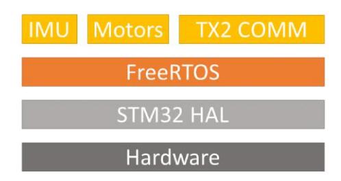
An STM32H743ZITx microcontroller (hereon STM32) on a Nucleo-H743ZI development board is used to execute the low-level software that handles communication with the inertial measurement unit (IMU) and servo motors in real-time. All the software, depicted in a simplified manner in Fig. 3, was written from scratch with the exception of FreeRTOS and the hardware abstraction layer provided by STMicroelectronics. All microcontroller code developed (including original drivers and APIs for Dynamixel AX-12A servo motors and the MPU6050 IMU) is available on GitHub for the RoboCup community to benefit from.
5 Electrical/Embedded Subsystem (continued)
The STM32 is pre-loaded with sets of joint angle trajectories generated by the controls team for specific scenarios. The high-level software on the Jetson specifies which trajectories the STM32 should be distributing to the motors at any given time based on strategy as well as IMU data. The IMU data is also used to perform real-time PID control on the STM32. The use of FreeRTOS paves the way for flexibility in control algorithms and utilization of more complex communication links with higher bandwidth and lower latency such as Ethernet, for which there is a module on the Nucleo-H743ZI.
5.3 Sensors, Actuators, and Communication
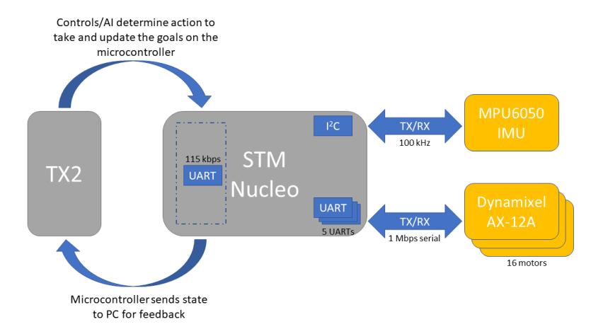
Motors: As depicted in Fig. 4, 16 Dynamixel AX-12A servo motors are controlled from this subsystem using 5 UARTs at 1 Mbps to increase parallelism. These motors are position-controlled due to limitations with the AX-12A motors. The motors on the legs are daisy-chained in sets of 3, and the remaining 4 motors for the arms are all on one chain.
IMU: A MPU6050 IMU is used to acquire and report information about the state of the robot's dynamics via 100 kHz I²C.
Communication: The STM32 uses a virtual serial port at 115 kbps to publish state information to a ROS node on the high-level software on the Jetson, and receive new goals.
6 Software Subsystem
Placeholder for section 6.
6.1 Robot Operating System (ROS)
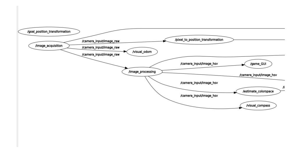
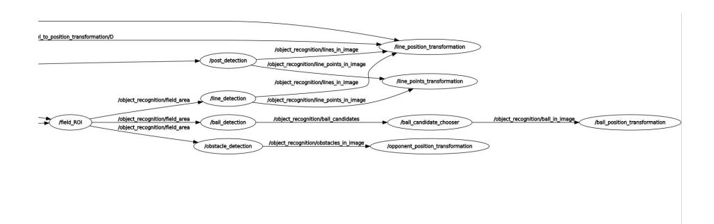
The software architecture is based on ROS (source code). Our architecture is largely based off the Humanoid League Messages by Hamburg bit-bots, however we have several design changes.
Instead of creating multiple ROI regions for different regions of interest (balls, field lines, etc.), we have a node called field ROI that first detects the grass and filters out all the objects that are not of interest. Then, geometry is used to locate the points on the field in 3D.
6.2 Computer Vision
Information is obtained from the images acquired by the camera through a series of filtering stages in the computer vision system. The filters are as follows:
- Field Detection A color filter supported by color space estimator (which obtains the color of the grass) to get the area of the field.
- Field Line Detection From the field area message we detect straight lines and find the individual intersections of all those field lines using Hough Lines.
6.2 Computer Vision (continued)
- Pole Detection The pole is detected using the Hough Line Transform. A high threshold value is set to ignore the vertical net lines and hence to only detect the vertical pole lines.
- Ball Detection A cascade classifier trained with Matlab locates the ball and sends its coordinates.
6.3 Path Planning
After testing a number of methodologies such as Dubin's path, we stuck with a much simpler algorithm for path planning that fit better with our mechanical and control subsystems. This algorithm calculates only vertical paths and rotations and puts the operations into a queue.
7 Current Research
Currently, humanoid robots are very expensive. A Darwin-OP which serves as a benchmark for humanoid robotics costs $12,000 USD [1]. This poses a big entry barrier for people interested in the field. UTRA team is researching several ways that can reduce the price of building a humanoid robot to make them more accessible to communities such as students and hobbyists. The team is working on two areas in this regard:
- Exploring 3D printing technology which can reduce labour effort, material costs and improve the overall design
- Creating a custom servo motor which will offer torque comparable to Dynamixel MX-64 motors but at a much lower cost.
This servo is planned to be made using off the shelf components such as a DC motor, an encoder and a gearbox. The servo will have a dedicated microcontroller for controlling the state of the motor. Such a servo motor has an estimated cost of no more than $100 USD. All of the work will be open source for the benefit of RoboCup participants and the robotics community in general.
References
- Trossden Robotics, Darwin-OP Humanoid Research Robot - Deluxe Edition. Available online at http://www.trossenrobotics.com/p/darwin-OP-Deluxe-humanoidrobot.aspx