Barelang FC Team Description Paper Humanoid Kid Size League of RoboCup 2019
Susanto, Hendawan Soebhakti, Eko Rudiawan Jamzuri, Andrey Karona Sitepu, Febry Alwan Putra, Jony Arif Ricardo, Junito Suroto, Eko Priono
Department of Electrical Engineering Politeknik Negeri Batam Jl. Ahmad Yani, Batam Centre, Batam, 29461 Kepulauan Riau, Indonesia
Abstract This paper describes the information of Barelang Football Club (Barelang-FC) Kid-size humanoid soccer robot. The improvement of robot system in this year focused on image detection, robot localization and side-kick ability. While the mechanical design, and robot architecture remains the same as before [1-2].
Keywords: humanoid robot, image detection, robot localization.
1 Introduction
In 2017 we able to get 4th place and it was the first time we participate to Robocup Competition in Nagoya Japan. In 2018 was the second participation of Barelang FC team in RoboCup competition and with better performance we achieved the 3rd place in Montreal Canada. The last two years of Barelang-FC participation in RoboCup competition, we discovered so many problems occurred while our robot competed with another team. The problem starts from the vision system which is failure to distinguish the object in the field. This is happened because of the complexity of parameters given by vision detection system which is needed to be tuned. The other problem appeared from robot localization, in the last two years [1-2] robot still playing itself without knowing where the robot position itself. This method made difficulty in order to change the strategy during competition. Therefore, in this year we focused on robot vision and localization to improve the drawback from the last two years.
2 Robot Architecture
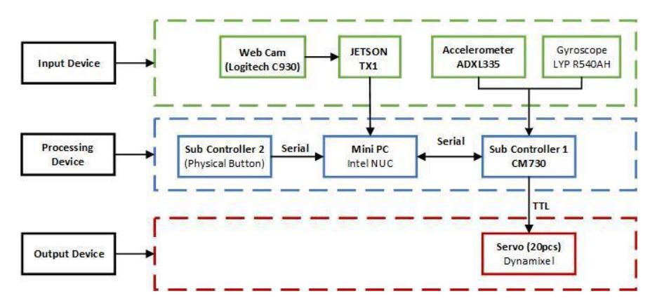
Fig.1 illustrated the block diagram for hardware system. In this block diagram, separated into three main parts such as input device, processing device, and output device. Input device denote to parts that responsible to collect environmental data surrounding the robot. The Web Cam Logitech C930 is still used to detect the object while additional Jetson TX1 proceed the image data from Web Cam to distinguish ball, goal, and white line in the field independently. The results of vision system from Jetson are distributed into intel nuc which is also communicated to two sub controllers via serial communication. In order to stabilizing robot while walking in the field, we used the accelerometer, and gyroscope as the feedback sensors. These two sensors are connected to the main processing device through sub-controller 1 by using ARM Cortex-M3 microcontroller. The sub controller 2 applied for reading physical button to start and stop robot behaviour.
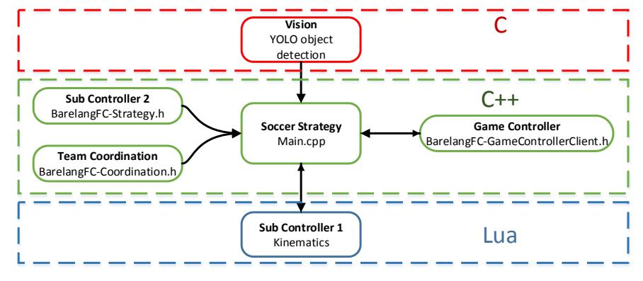
The software parts of Barelang-FC described in Fig. 2. The software part consists of vision system, strategy, and the kinematic. YOLO v3 has been chosen as vision system programmed by C++ for light computation cost to the Jetson TX-1. Incoming data from vision system, robot's team coordination and game controller will be uses as input for robot algorithm strategy. The processing of robot strategy will produce path planning system for robot to acts as kinematic system according to the soccer strategy.
The improvement from the last two years [1-2] lies in the robot vision and the team coordination which are emphasized in this year.
3 Mechanical Design
For the mechanical design, we still use existing design from previous year [1-2] presented in Fig. 3. Existing design has an advantage of its performance in last two years gave a sufficient result to playing in the field during the competition. Mechanical designed by aluminum with a thickness of 3 mm and 6 mm for the main body. There were two models of robots, the first one with 58 cm height (2017 version) and the other with 64 cm height (2018 version), where the 2017 version used Dynamixel MX-28 and MX-64, while the 2018 version uses Dynamixel MX-28, MX-64 and MX-106. The detail of actuator that used in this model can be seen in Table 1.
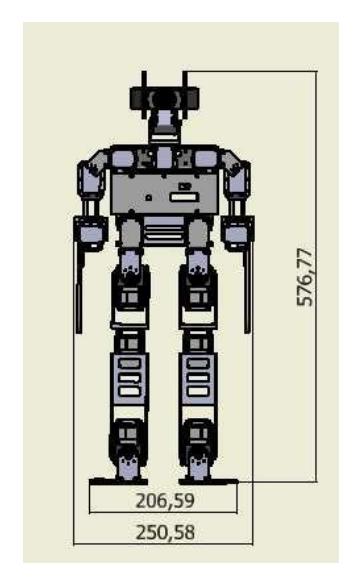
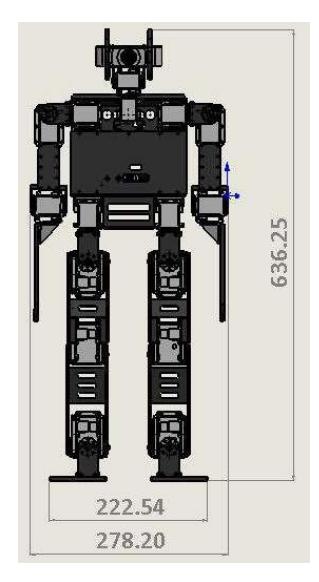
Table 1. Comparison actuator of old and new robot design.
| Sub Body | 2017 Version | 2018 Version |
|---|---|---|
| Neck | MX-28, MX-28 | MX-28, MX-28 |
| Shoulder | MX-28, MX-28 | MX-64, MX-64 |
| Arm | MX-28 | MX-64 |
| Hip | MX-64, MX-64, MX-64 | MX-106, MX-106, MX-64 |
| Knee | MX-64 | MX-106 |
| Ankle | MX-64, MX-64, MX-64 | MX-106, MX-106, MX-106 |
4 Vision System
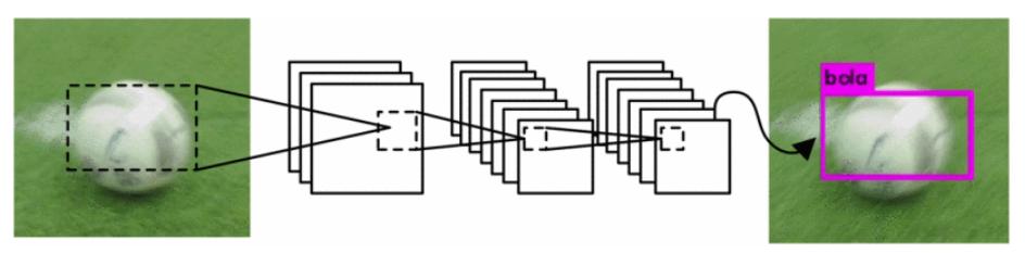
Last year, vision system still using some steps in order to detect the ball and goal. The step such that detecting the object, convert to color space, filter the specific color, do the morphological process, detecting contour using convex hull and masking the image [2]. In this year, vision system of robot developed by using deep learning as YOLO v3 generated in Jetson TX1 [3]. Barelang-FC already implemented the YOLO for vision system, YOLO system is tended to unify the separate components of object detection becomes a single neural network. It makes bounding box of entire image feature should be considered [4].
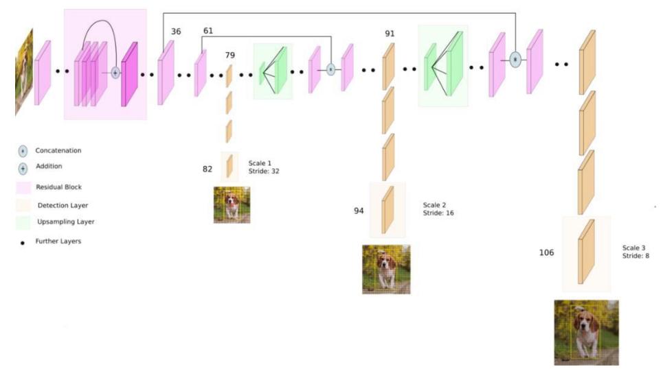
Only it took much time to learning the object and very tough to implement in the real time. Meanwhile, YOLO v3 gave promising result with light calculation and more precision object detection. YOLO v3 uses a variant of Darknet, which originally has 53 layer network trained on ImageNet. For the task of detection, 53 more layers are stacked onto it, giving us a 106 layer fully convolutional underlying architecture for YOLO v3 [3].
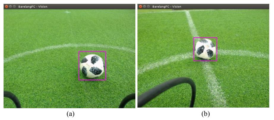
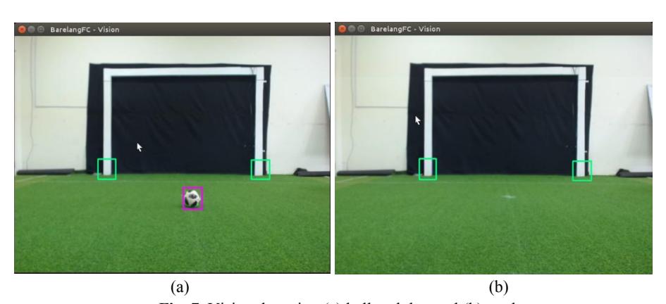
This method already implemented in robot and gave the result which can be seen in Fig. 6. When robot detected the ball inside the white line and outside the white line, vision remains detect the ball whenever it has some other disturbance precisely. Another, experiments illustrated in Fig. 7 to detect the goal and ball in some distance. Fig. 7 (a) we do experiment to detect the ball and goal in the same time, by using this method it can distinguish ball and goal correctly. When the ball removed from the field which seen in Fig. 7(b), vision remains detect the goal accurately.
The coordinate of ball and goal also can be taken using this method. The results of ball and goal coordinate can be seen in Fig. 8. The other information gave by this method is the amount of frame which can be detected during detecting the ball. From Fig. 8, the result of detecting object can be done evenly around 35.7 FPS in order to detect the object as expected.
5 Localization
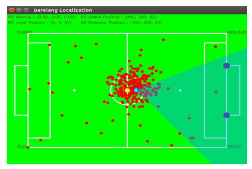
In this year, we apply the particle filters in order to do the localization as done in [5]. In this work, we spread around 100 random particles in the field which generated from software and let the vision and odometry detect the filter around the robot. The illustration of this method can be seen in Fig. 9. We assume the blue dot is the robot nearest estimated robot position, and we let the vision calculate the distance between goal. This distance data will be used to predict the position and coordinate of the robot. The localization of robot itself can be determined by using the prediction of position and coordinate robot. The odometry is used for input calculation of particle filter.
6 Side Kick
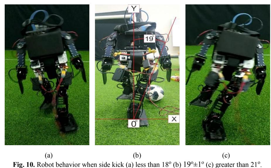
In addition, we also developed the motion kick of robot to do sidekicks by manipulate the position of the robot. Kinematic of sidekick motion is followed by axis relation of torso and foot support to prevent robot from falling when do side kicking. For x axis of torso and foot support should be parallel and y axis should be intersecting, so that robot will be stable when do side kicking. We do the trial and error to get the offset angle of robot to perform sidekick motion. Table 1 show the result of robot behavior respecting to theta angle of one-foot support.
Table 1. One-foot support theta.
| Theta (degree) | Robot Behavior |
|---|---|
| < 18 | Falling-down |
| 18-20 | Not falling-down |
| > 20 | Falling-down |
Experiments illustrated in Fig. 10 to see robot behavior through incremental testing theta on robot to do side left kick. Fig. 10 (a) we do experiment of theta less than 18° with the result robot falling to left. When theta greater than 20° robot respectively falling to the right which seen in Fig. 10(b). Within range theta of 19° (±1° ), design of Barelang-FC robot acquires the ideal angle for one-foot support side kick which can be seen in Fig. 10 (b). This ability is needed to get more faster on kick execution time, so the robot without aiming robot heading to goal position, robot can shoot the ball to the goal.
7 Conclusion and Acknowledgments
The improvement of the robot in this year, focused on robot vision, localization and side-kick performance. From this effort, robot not only can detect the object but also distinguish the ball and goal in the same time precisely. Another work, we also implemented the localization method using particle filter with a good result in order to understand the position of robot itself and the opponent. In addition, we improved the motion system to do sidekick to accelerate the ball displacement. Finally, Barelang-FC team are confidence to compete with other teams in RoboCup 2019 Sidney Australia.
References
- Susanto, Hendawan Soebhakti, Eko Rudiawan, Barelang FC Team Description Paper Humanoid Kid Size League of RoboCup 2017.
- Susanto, Hendawan Soebhakti, Eko Rudiawan, Barelang FC Team Description Paper Humanoid Kid Size League of RoboCup 2018.
- Redmon, Joseph & Farhadi, Ali. (2018). YOLOv3: An Incremental Improvement.
- Susanto, E. Rudiawan, R. Analia, P. Daniel Sutopo and H. Soebakti, "The deep learning development for real-time ball and goal detection of Barelang-FC," 2017 International Electronics Symposium on Engineering Technology and Applications (IES-ETA), Surabaya, 2017, pp. 146-151.
- W. Adiprawita, A. S. Ahmad, J. Sembiring and B. R. Trilaksono, "New resampling algorithm for particle filter localization for mobile robot with 3 ultrasonic sonar sensor," Proceedings of the 2011 International Conference on Electrical Engineering and Informatics, Bandung, 2011, pp. 1-6.