EROS - Team Description Paper for Humanoid KidSize League, RoboCup 2019
Aulia Khilmi Rizgi, Ryan Satria Wijaya, Ilham Fakhrul Arifin, Mochamad Ayuf Basthomi, Cipta Priambodo, Rokhmat Febrianto, Ibrahim Musthofainal Akhyar, Miftahul Anwar, Anhar Risnumawan, Achmad Subhan Khalilullah
Laboratorium Robotika Politeknik Elektronika Negeri Surabaya Jl. Raya ITS Kampus PENS, Sukolilo 60111, Surabaya, INDONESIA
Abstract This paper describes the overall system of the RoboCup Humanoid Soccer League KidSize team, EROS from Politeknik Elektronika Negeri Surabaya as required by the qualification procedure for the competition to be held on July 2-8, 2019 in Sydney, Australia. Our robot specification including mechanical architecture, software development, and hardware construction is described. We also describe our robots improvement, and hopefully, we can participate in RoboCup 2019 and get an outstanding result in Humanoid Soccer League KidSize.
1 Introduction
EROS (EEPIS Robot Soccer) is humanoid robot soccer which researched by undergraduate students at Politeknik Elektronika Negeri Surabaya (PENS), Indonesia. Our robot has been able to play soccer and participate in competition in RoboCup Humanoid KidSize League [3]. The last participation is in RoboCup 2017, Japan and must stop in Round of 16, a worse result than before (Round of 8 in RoboCup 2016 and Semi-final in RoboCup 2014 and 2015). It happened because our robot can no longer adapt to the rules of the game.
The main problem of the previous competition is object perception. EROS cannot look at the ball that has a white contour with patterns. Furthermore, mechanic and hardware specification becomes no longer appropriate. Therefore, we improve our robot system from the mechanical issues until the high-level programming. In this paper, we describe our robots improvement, and hopefully, we can participate in RoboCup 2019 and get an outstanding result in Humanoid Soccer League KidSize.
2 System Overview
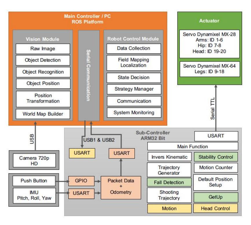
EROS has a height of approximately 58 cm and about 4,7 kg weight with 20 DoF (Degree of Freedom). In the head of the robot mounted a camera with 720p resolution and 73° wide angles. In the trunk of the robot mounted mini-PC, subcontroller, and battery so that the robot can move freely on the field.
The entire system uses ROS (Robot Operating System) Kinetic Kame and Ubuntu 16.04 platform. All detection, decision, and control system are in mini-PC with Intel Core i3-5010U 2.10GHz 4 cores, 4GB DDR3 memories, and SSD as the storage. Object detection has high priority and uses three cores to get a better result. The remaining core for others node that runs inside mini-PC, such as wireless communication that uses 2.4GHz frequency band. Furthermore, walking trajectory, joint control, and low-level control based on ARM 32bit.
3 Mechanical Architecture
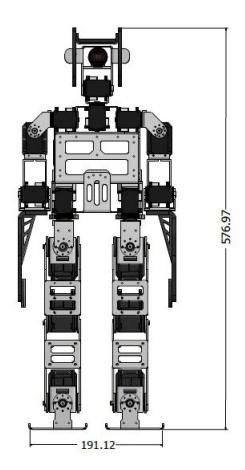
The whole shape body of the robot is just like a kid-sized humanoid robot in common. It has 20 DoF of the total which consists of 2 DoF on the neck, 3 DoF on each arm, and 6 DoF on each leg. The most used materials for building this robot are 2 mm thickness of aluminum and several types thicknesses of acrylics. The actuators that we use are servo motors of Dynamixel MX-64 for the leg and Dynamixel MX-28 for the rest of it. The illustrated of the robot can be seen in Fig. 2.
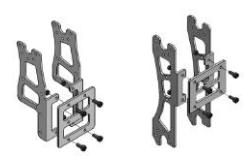
In our previous work, we used 2 mm thickness of aluminum sheet that we have done machining it in CNC machine before and then bent it later to make a form of a link of the robot. However, we just aware that using a bent aluminum sheet will reduce the precision of some part because we did it manually without using sheet metal folding machines. Therefore, instead of using a bent aluminum, we decided to change it all with an aluminum angle (which has the same thickness) to link the robot. This process gives a better precision and more robust results than before. Fig. 3 shows the joint process of a link using an aluminum angle.
4.1 Field Detection
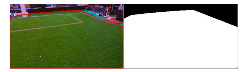
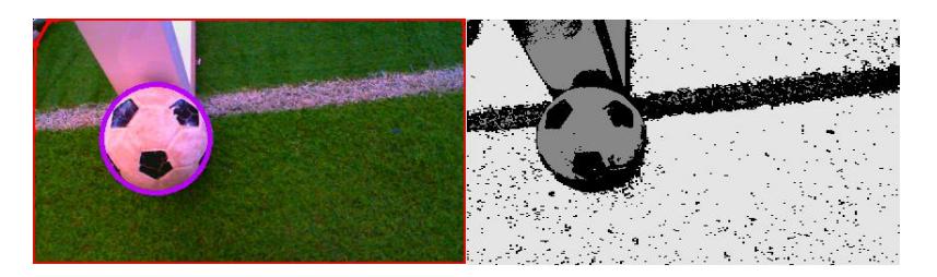
In detecting the field, we use the YUV color domain instead of RGB because luminance in RGB cannot be separated from the chrominance [1]. However, the green color in the field has hollow-cavities so that when the robot process the images there is noise which requires morphological methods to reduce the existing noise. The morphology includes dilation, erosion, and closing. After obtaining near-solid binary colors, we apply the convex hull algorithm [6] to get the entire field captured by the camera as shown in Fig. 4, the red line displays the results of the field detection. Accuracy in getting the convex hull value depends on the morphological parameters that used when reducing noise in detecting the field [5].
4.2 Ball Detection
We use the Cascade Classifier method that has been researched in [7] to detect human faces. We apply this method to detect the ball in the field with the LBP (Local Binary Pattern) feature. Cascade Classifier used non-pixel features to approach object detection and applied to the region of interest until all classifiers (stages) passed. A ball is a circular object with a pattern in it, and the LBP approach is in a grayscale image that contains a pattern, which makes us use this feature. However, LBP is not effective against multi-resolution and rotational invariant textures. To handle this, we applied this approach [4] to obtain positive and negative sample data for training data.
Data must be authentic, which is taken from the camera mounted on the robot and also in every condition of the ball in the field. Positive samples are the image of the ball. While the negative samples are a picture without a ball in every condition that might happen in the field, the number of negative samples must be at least two times that of positive samples.
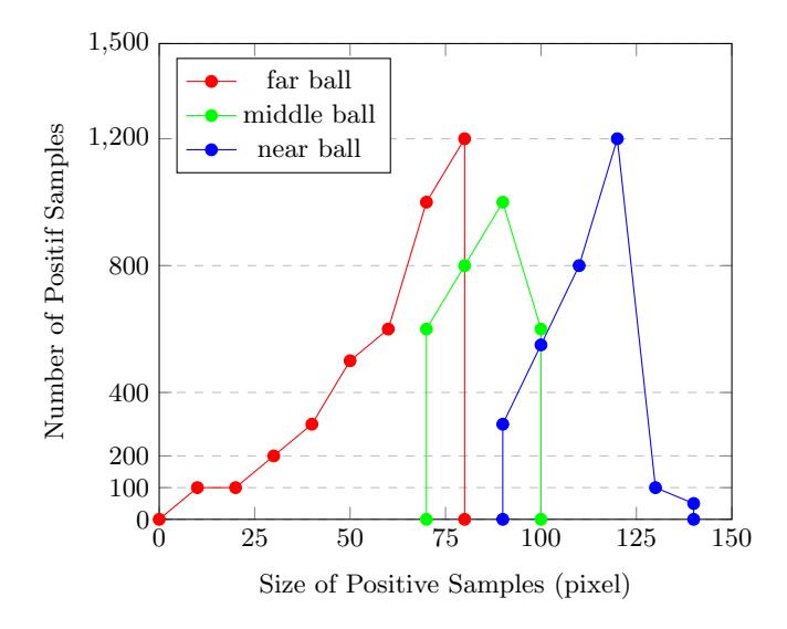
The multi-resolution case is a major problem for this condition —the smallest and largest ball size in the frame up to 15 times enlargement. The smallest ball size represents the farthest ball and the largest size for the closest ball. We use data distribution (Fig. 5) in collecting positive samples. In this way, we get three parameters after training data. After processing the training data, the robot can detect the ball well where the ball is in the field line and near the goalpost (Fig. 6).
We are also still trying to improve our ball detection method. To get better improvement, we also try to implement visual perception from another team such as NimbRo AdultSize team that get an outstanding result in recent competition [2].
4.3 Localization
We use the line of the field detection to recognize robot's position on the field. The position of the robot always changes when the game is on, such as approaching and looking for a ball. The position of the line (red line in field detection) on the image also changed because the robot vibrates during the walking phase. For that, we need a lot of accurate data so that the robot can easily recognize its position. We use the kNN (k-Nearest Neighbor) algorithm to identify positions. Some of the data that has been taken in actual conditions is compared to the actual data when the robot checks the position. In this way, the robot can determine its position on the field.
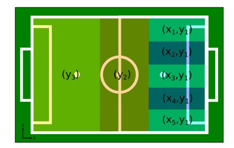
As in Fig. 7, the position of the robot in the field divided into seven parts. When the attack direction follows the y-axis (to the right), the position in the xaxis only done near the opponent's goal (about 3 meters), this is done to reduce calculations in the process because of limited hardware embedded in the robot. Therefore, the data distribution for kNN is only in these seven positions.
5.1 Communication between Robot
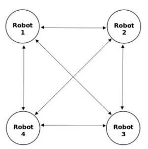
We use UDP (User Datagram Protocol) as our data travel protocol to send and receive the data between robot. The illustration of the data flow diagram can be seen at Fig. 8
The robot sends its state to all robot and receives other robots state too. After that, every robot that already receives other robots state, will process that state and send the result of the process to other robot and so on.
5.2 Monitoring and Debugging
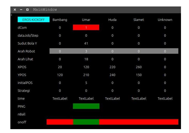
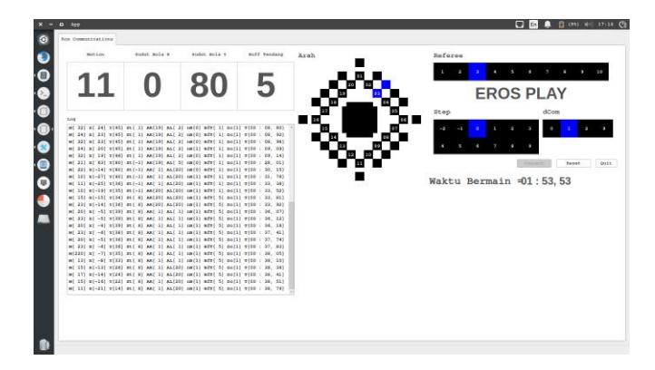
Monitoring is the way we use to know the state of the robot like the direction of the robot and whether the robot detects the ball or not. We have two types of monitoring, namely EROSTeamPlay and EROSDebugger.
EROSTeamPlay is the monitoring that receives the data of the robot through the socket. It has a similar way with a Communication between Robot. The only difference is that EROSTeamPlay only receives the state of the robot and not sending back its data.
EROSDebugger is our new software to debug every state of our robots. It uses the feature of ROS that is MultipleMachine. This software receives the data of the robot by subscribing the message that published by the robot. Moreover, it little bit faster (nearly real-time) than using UDP. We still develop this to make it easier for us to debug the robots.
6 Motion
EROS has undergone many developments in the method and control of walking. In the case of walking, the angular speed control has been successfully implemented along with the joint trajectory control. Further optimization has also been carried out by controlling acceleration and deceleration which makes the robot more stable when moving towards maximum speed. The addition of optimization during landing has also been applied to reduce the risk of servo motor damage to the robot. In the case of kicking motion has also been optimized by using joint trajectory controller.
On the EROS robot also could balance themselves with Linear Inverted Pendulum Modeling (LIPM). Also, we still on work to adding force sensor in the toe to get better stability walking on the artificial grass.
7 Conclusion
We have described our development in EROS Humanoid Robot. The development has been implemented in the Indonesian Robot Competition. Moreover, we are working further development related to all aspects of RoboCup Competition. Hopefully, we have a good match with all the teams in Sydney, 2019.
References
- James Bruce, Tucker Balch, and Manuela Veloso. Fast and inexpensive color image segmentation for interactive robots. In IROS 2000, 2000.
- H Farazi, P Allgeuer, and S Behnke. A monocular vision system for playing soccer in low color information environments. in roceedings of 10th workshop on humanoid soccer robots, ieee-ras int. In Conference on Humanoid Robots, Seoul, Korea, 2015.
- Achmad Subhan Khalilullah, Naufal Suryanto, Adi Sucipto, Imam Fajar Fauzi, Fendiq Nur Wahyu, Muhammad Lutfi Santoso, Krisna Adji Syahputra, Aulia Khilmi Rizgi, Ilham Fakhrul Arifin, and Ryan Satria Wijaya. Eros team - team description paper 2017. 2017.
- Timo Ojala, Matti Pietikainen, and Topi Maenpaa. Multiresolution gray-scale and rotation invariant texture classification with local binary patterns. TPAMI 2002, 2002.
- Aulia Khilmi Rizgi, Muhammad Muhajir, Edi Sutoyo, Imam Fajar Fauzi, Rokhmat Febrianto, Cipta Priambodo, Miftahul Anwar, Anhar Risnumawan, and Martianda Erste Anggraeni. Improving field and ball detector for humanoid robot soccer eros platform. In International Electronics Symposium (IES-ETA), pages 101–105, 2018.
- Jack Sklansky. Finding the convex hull of a simple polygon. PRL, 1982.
- Paul Viola and Michael Jones. Rapid object detection using a boosted cascade of simple features. In CVPR 2001, 2001.