ZJUDancer Team Description Paper Humanoid Kid-Size League of Robocup 2019
Wu Fan, Xinxin Chen, Jiajun Jiang, Chenghui Li, Yusu Pan, Chunlin Zhou, Rong Xiong
State Key Lab. of Industrial Control Technology, Zhejiang University, Hangzhou, China
Abstract This paper describes the robot system designed by ZJU-Dancer, a RoboCup Humanoid League team from Zhejiang University, China, as a qualification requirement of the competition to be held in Sydney, Australia 2019. Full details of our robot including mechanical and electrical design, sensors and software architecture are described. This year we adopted foot sensor on robots in competition, modified mechanical body plan and simplified circuit board. Before the next game, we will focus on improving the gait performance, self-localization precision, and strategy. With reinforced robots, we hope to get a better result in 2019.
Keywords: Humanoid Robots, Force Sensor, Deep Learning, Camera Calibration
1 Introduction
In this paper, we describe our robot system for the RoboCup Humanoid League, designed by ZJUDancer. This year we made a large progress in image processing and gait control, which contributes to the more intelligent robots.
2 Overview
The robots developed by ZJUDancer for RoboCup 2019 are fully autonomous humanoid robots with the capability to play varied parts as a team in the competition. Fig. 1 shows our robots.
Table. 1 shows the general specifications of our robots. Each robot is fixed to the size and weight limitations of the competition, which can communicate with the GameController and other players the wireless network. Details will be shown in the following sections.
We have taken part in RoboCup for more than 10 years, during which we improved our robot system continually. Over recent years, our experiences of participation are listed as following:
– 2015(Hefei): We won the second place this year. We use Intel Core i7-5500U as our main controller and ATMEL Mega128 as the motor controller.
- 2016(Leipzig): We won the second place this year. Since the earth magnetic field sensor was discarded, we used monocular visual odometry to localize the self-position of robots.
- 2017(Nagoya): We won the second place this year. We started researching on foot force sensors and adopted the ROS framework as middleware.
- 2018(Montreal): We won the fourth place this year. We modified the particle filter algorithm and camera calibration method. In addition, the foot sensor was applied in the competition.
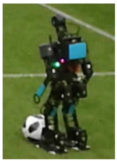
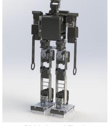
Table 1: General Specifications
| Item | Description |
|---|---|
| Team Name | ZJUDancer |
| Number of DOF | 18 |
| Height | 620mm/700mm |
| Width | 35cm |
| Weight | 4kg |
| Computing Unit | NVIDIA Jetson TX1/TX2 |
3 Hardware
3.1 Electrical Specifications
This year, NVIDIA Jetson TX2 are adopted as our main controller, whose specifications are shown in Table 2. Motor controller and camera controller are merged into a single controller due to the better computing performance of Jetson TX2. The motor part executes the movements of all directions and maintains the balance, while the camera part works on object detection, selflocalization, strategies, and multi-robot communications. To meet the requirement of a smaller chest size, we redesign the circuit board and make the total electrical system slimmer. Moreover, we adopt a new foot sensor board for walking more steadily. The electrical architecture is shown in Fig 2.
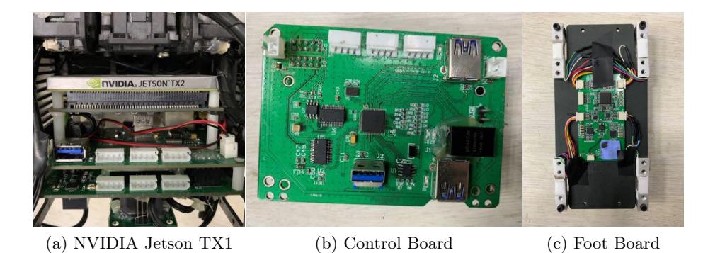
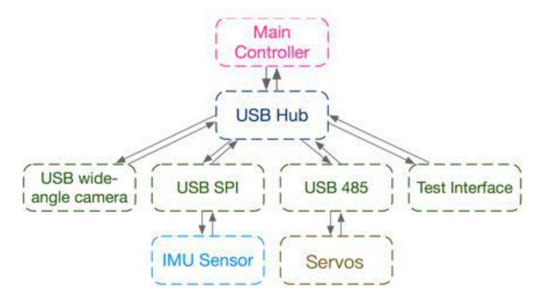
Table 2: Electrical Specifications
| Main Controller | |
|---|---|
| CPU | NVIDIA Jetson TX1/TX2 |
| Flash | 16GB/32GB |
| RAM | 4GB/8GB |
| OS | Ubuntu 16.04.5 LTS |
3.2 Mechanical Specifications
This year we mainly modify three parts in the mechanical structure of our robots. Firstly, we unify the size of our robots to simplify the design and manufacture of the components. Besides, we reduce the thickness of the total thorax and remove the unnecessary components which are used to connect the different circuit boards. Another significant improvement is that we reduce the spacing between the two hip-joints. Since we need enough power to support the motion of our robot, we move one of the batteries which used to be between two hipjoints to the back of our robot. Although this change results in a higher center of gravity, it seems that the gait of the robot is not considerably affected.
Our robot has two legs, two arms, one trunk, and one head, which belongs to a classical planning. We have two specifications of our robot: one is of about 620 mm height and the other is nearly 700 mm which has longer legs and neck. The actuators for those two version robots are listed in the Table 3. Each robot is driven by 18 servo motors: six in each leg, two in each arm and the last two in the head. The six-leg-servos allow flexible leg movements. Three orthogonal servos constitute the 3-DOF hip-joint. Two orthogonal servos form the 2-DOF ankle joint. One servo drives the knee joint. The motor distribution is different but the DOF is the same.
Table 3: Motor Type and Distributions of DOF (Totally 20 DOF)
| Part | Rotation Axis | Actuator |
|---|---|---|
| Neck | Yaw, Pitch | MX-28, MX-28 |
| Shoulder | Pitch | MX-28 |
| Arm | Pitch | MX-28 |
| Hip | Roll, Yaw, Pitch | MX-64, MX-28, MX-64(106) |
| Knee | Pitch | MX-64(106) |
| Ankle | Pitch, Roll | MX-64(106), MX-64 |
3.3 Sensors specification
- Servo: DYNAMIXEL MX-64 and MX-28 with joint angle feedback, which benefits to the closed-loop control.
- IMU: Analog device ADIS16355 featured with tri-axis gyroscope, and triaxis accelerometer, which conduces to keep the balance of our robot.
- Image sensor: OmniVision OV2710 with 150-degree FOV, which provides a wider view angle, and improves the perception eciency.
4 Software
Our software architecture remain almost the same this year. The main work is to enhance the modules including the vision module, localization module, behavior module, etc. Detailed improvements we have made are introduced in the following subsections.
4.1 Cognition
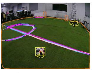
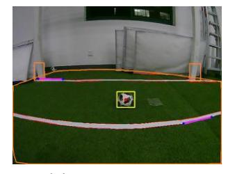
In order to use the goalposts to assist in self-localization, we have improved its detection. Since the traditional method takes vast computing resources and can not provide accurate results, we attempt to recognize goal, robots, and balls at the same time using a deep learning approach. However, the detection of a whole goal is defective, and our robots can hardly ever observe it. Thus, we only detect the bottom of goalposts and get fairly reliable results, as shown in Fig 4.
4.2 Calibration
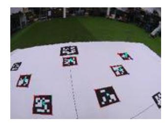
Calibrating extrinsic parameters is an essential but laborious process after transportation or hardware modification. The previous extrinsic calibration method requires an empty field to take various pictures and label preset points on every picture manually, which takes a lot of time and manpower. This year, we adopt the aruco marker and let robots perform an automatic detection and labeling. Although the recall rate is not very high, the re-projection error of labeled point becomes much lower and the precision is almost 100%. Fig 5 shows this approach.

4.3 Navigation
Last year, the self-localization of our robots mostly depended on the center circle, which lead to a wrong location estimation and deviated shooting direction. This year, since the recognition of goalposts has been improved, we add them as reliable landmarks for the particle filter. Furthermore, we make additional improvements in the resampling part so that the location estimation can be more robust. As a result, our robots are able to achieve a high-precision selflocalization in the playing field.
4.4 Behavior
This year, we refactor our behavior framework by a standard behavior tree. The basic logic is almost the same as the previous version, but the whole architecture is more clear and convenient for modifying and adding new features quickly. In addition, we add a new defender role which patrols on our own half and stares at the center circle to ensure its location estimation accuracy. Moreover, we try to add some team play features such as sharing the ball position and avoiding the collision when multiple robots seeing the ball at the same time. However, due to some network defects, these features didn't work in RoboCup 2018. We will continue to fix such problems and improve the stability of our strategy.
5 Motion
Since the previous version of the gait generation algorithm had fewer advantages compared with other teams during the RoboCup 2018, we decide to refactor our motion module this year. The motion module mainly consists of following four child modules:
- IO: IO module manages the external devices including servo, IMU and foot pressure sensor. This module provides an interface to send instructions to actuators or get readings from sensors.
- Kinematics: Inverse kinematics module is used for calculating the joint angles when the robot acts in a known gesture. We can get the analytic solution of one leg by some geometry methods. Based on that, we can get two leg joint angles when the robot is standing on the ground. We also use forward kinematics to estimate the position of the center of mass of the robot. Getting the estimation helps the observation of the state of the robot for controller designing.
- State Manager: This module is used to manage the robot task state. Generally, robots have to cope with unexpected situations, such as collision and falling down. State manager helps to estimate what situation the robot has come cross and give appropriate action command. It is also the interface between behavior module and motion module.
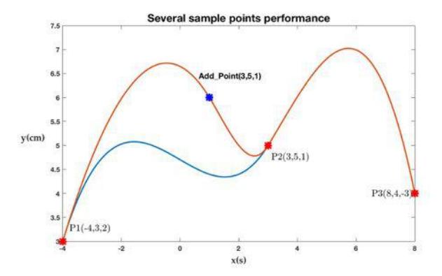
- Trajectory Generation: This module is used to plan discrete footprints and generate smooth trajectories for joints, we are going to develop a new parameter tuning graphical interface to customize some piecewise cubic spline curve like Fig. 6 via determining the points position and slope artificially. We will try some intelligent control algorithms to modify these curves if the development well proceeds.
6 Conclusion
This paper describes the main structure of our robots. Our team, ZJU-Dancers, have made a significant progress in both hardware and software. In terms of hardware, we simplify the electrical system and make the mechanical structure stronger by integrating the function of the motor controller. On the side of the software, we achieve the detection of the bottom part of the goalposts and change the camera calibration method. With respect to the motion module, we try some new methods for gait planning and path planning. We would like to share our experience and hope to have good competitions with all the teams in RoboCup 2019, Sydney.
References
- Craig, J.J.: Introduction to robotics: mechanics and control, vol. 3. Pearson/Prentice Hall Upper Saddle River, NJ, USA: (2005)
- Kajita, S., Hirukawa, H., Harada, K., Yokoi, K.: Introduction to humanoid robotics, vol. 101. Springer (2014)
- Pan, Y., Peng, B., Jiang, C., Li, C., Zhou, C., Xiong, R.: Zjudancer team description paper