Technical description: Pal Technology
Davide Faconti, Francesco Ferro, Joan Poyatos, Alcides Strecth Monteiro, Oriol Torres, Sergio Garcia
Pal Technology, robotics department. Barcelona, Spain.
http://www.icarustechnology.com · http://www.paltechnology.com
Abstract In this document the humanoid robot "Arabot" will be presented. Arabot was built by the company Pal Technology as research platform in the field of service robots. The hardware design has the primary goal to achieve good dynamic performance and extreme lightweight. The specifications of the first prototype are described below. Pal Technology wants to participate to Robocup 2006 in the humanoid league to benchmark the results obtained in the field of locomotion, localization and path planning.
1 Introduction
Humanoid robotics is a field of research that has dramatically grown in the last decade. To develop this kind of autonomous robots, it is necessary to investigate many different subjects, in the field of mechanics, electronics, automation control and biomechanics. From the software point of view, we need the contribution of computer vision, navigation, voice recognition and learning.
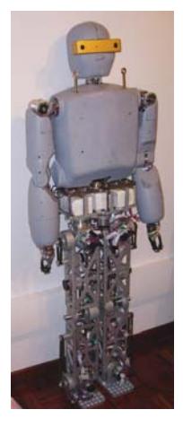
The main purpose of our project is to develop a first prototype with medium size (140 cm) but the lowest weight that it is possible to achieve without compromise on autonomy, walking velocity and manipulation capability. Lightweight is important because it makes the robot easier to transport and safer when used close to human beings. In the design of Arabot we tried to achieve a versatile platform of research in the field of humanoid service robots. Therefore, we wanted to optimize some of its characteristics, especially from the point of view of the mechanical construction. Arabot is still a prototype, and many tests are needed to know the maximum velocity and battery autonomy that it can achieve. Nevertheless, computer simulation and preliminary experiments exhibit satisfactory results.
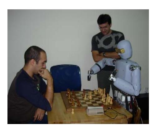
The upper body of the robot can already perform tasks which require high precision, such as chess playing; using distance sensors on the robot's hand and the stereoscopic vision system, the robot can localize the chessboard and the piece to move, with up to 99% of success on the "pick and place" task.
2 Overview of Arabot
In this section, the preliminary specifications of the robot are introduced; in the development phase we used the best components available today, in terms of motors, reducers and embedded computers.
2.1 Specifications
The kinematic structure of Arabot and the number of degrees of freedom is very similar to other humanoid robots [1,2,3]. The number of degrees of freedom is summarized in Table 1; it must be noted that the hip joint has 3 DoF intersecting in one single point. This structure is more similar to the human one, since the femur bone is connected to the ilium with a spherical joint.
The 2 DoF of the waist joint are very important to increase the mobility and workspace of the upper body. In the future, when the range of motion of the legs will be increased, the waist bending will be useful to achieve complex behaviors, such as crouch or recover from a fall.
Specifications of Arabot. Some characteristics as autonomy time, weight and processing power are nearly state-of-the-art for humanoid robots of this size.
| D.O.F. | Value |
|---|---|
| Legs | 6x2 = 12 |
| Arms | 6x2 = 12 |
| Waist | 2 |
| Head | 2 |
| Hands | 1x2=2 |
| Total | 30 |
| Specification | Details |
|---|---|
| Weight | 36 Kg (batteries included) |
| Height | 140 cm |
| Walking velocity | 1.2 Km/h (expected) |
| Arm payload | 1 Kg per arm |
| Computer | PC-104, Pentium M processor, 2.0 Ghz |
| Electronic | Motor control boards with CAN bus, Wireless module |
| Sensors | 6 axis force/torque sensors, Tilt sensor, Firewire stereo camera |
| Batteries | Rechargeable Lithium-ion. Maximum autonomy walking continuously: 2 hour |
2.2 Mechanical design
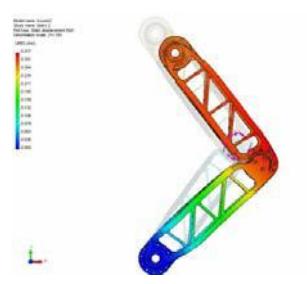
A stiff mechanical structure reduces oscillations and produces a more stable and dynamic movement; usually, stiffness comes at the cost of weight, but this should be avoided on an autonomous walking robot. To reach the limits of this tradeoff between stiffness and weight, extensive FEM analysis (Fig.4) has been done on critical parts. Shape and thickness has been evaluated and modified.
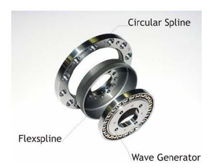
Most of the frame is made of aluminum but, in future improvements of the robot, composite material and carbon fiber will be used. Most of the reducers used on the robot's joints are Harmonic Drives (HD); the reducer is made of 3 concentric components: a Wave Generator connected to the motor (input), the Circular Spline and the Flexspline, a deformable cylindrical component used as output as represented in Fig. 2.
This technology has several advantages compared to planetary gearheads: despite their low efficiency at higher velocities, they have nearly zero backlash, and the best "torque to weight ratio". In addition, Harmonic Drives are back-drivable, an important feature especially on the legs, which experience impacts with the ground during the normal walking gate. To optimize the robot's dimension and weight, we designed the external frame of the HD with the bearing needed by the three components.
The motors used are all brushless. This kind of motors is preferable to normal DC motors with brushes, since they can provide higher power/weight ratio, more efficiency, longer life and less electro-magnetic emission (since the commutation is done electronically).
This selection has some marginal withdraws: first of all, the robot needs extra cabling (because of the hall sensor integrated in the motors) and a more complicated control and driving electronic.
The motors well selected to have sufficient force and power to achieve fast walking and go up and down stairs.
In the table is represented the maximum speed and torque that the motor reducers can generate. Such values can be limited by the reducer, the maximum motor torque (that is NOT the stall torque), the power rating of the electronic controllers or the voltage of the batteries.
| Component | Max Torque | Max Velocity |
|---|---|---|
| Motors of the arms | 15 Nm | 50 rpm |
| Motors of wrist and neck | 3 Nm | 55 rpm |
| Motor of the legs | 45 Nm | 40 rpm |
2.3 Main computer
The robot's main computer has several tasks: kinematic control, path planning in real time, artificial vision, voice synthesis and recognition. A very fast processor is therefore needed, but dimensions, weight and power consumption of the whole system must be taken into account.
The platform chosen was a Pentium M processor, which provides 400 MHz of processor bus at 2.0 GHz of processor frequency for faster execution of instructions at lower power. The manual voltage and frequency selection allows better match of performance to application demand. The x86 architecture allows the programmers developing the application in a desktop host environment and, once the application is stable, to download it into the embedded target system.
The form factor of the main computer is PC-104 and PC104+ to provide expandability to the CPU-board and reduced dimensions. In the stack there are 4 PC-104 expansion boards: a double CAN controller, which can achieve a whole bandwidth of about 2 Mbps, a Firewire (IEEE-1394 communication) board, used to receive images from the cameras, a PCMCIA port, for wireless connectivity and, last, an A/D converter, to read the input of the 6 axis force/torque sensors on the feet.
2.4 Motion controllers and sensors
The motor control boards have been developed to work with a large range of power supply from 20 to 50 volts; maximum continuous power is 150 Watts on most of the joints and 200 Watts on the larger motors.
Any board has its own DSP and can perform position control with current limitation, doing at the same time a micro-interpolation of the target position given by the main computer at 100 Hz.
Current limitation integrated in the position control loop is an important feature, having two main advantages: it protects the motor and the reducer in case of unexpected force, and it make possible to simulate torque control on the joint. All the boards have full-speed CAN bus, to communicate in real time.
On the feet, 6 axis force/torque sensors are used; this kind of transducers make possible to control the equilibrium of the robot during walking. Body tilt measurement is also necessary for stable walking, as it contributes to keep torso upright. A new tilt sensor has been developed for this robot. The information from 2 accelerometers and 2 gyros is processed by a DSP to get reliable and robust measurements of tilt angles.
2.5 Vision system
Vision is provided by a stereo digital camera using IEEE 1394 (FireWire) interface for output and power. The cameras are 640x480 (VGA) progressive scan CMOS with a standard miniature lenses. A high frame rate is 30Hz for 640x480 with automatic control of exposure, gain and black level.
The robot is equipped with a FPGA that analyzes in real time the stereo pairs and creates a "depth map". The use of the FPGA frees up the host PC from the expensive stereo calculations.
The stereo images are processed to produce a range image, also called a disparity image, which encodes the distance to each pixel in the image, based on triangulating matched regions in the left and right images. From the disparity image, the 3D structure of objects can be re-created. The chip removes automatically the lens distortions from the images (the results are called rectified images).
2.6 Batteries
The robot is powered by 3 packs of Lithium-ion batteries. They were preferred because of their higher power density (the ratio between their capacity and the weight and dimensions is superior to other technologies as Nickel-Metal).
The biggest battery pack has a rated voltage of approximately 47 volts. It powers the larger motors of the robot, located on the legs. A second and third pack of 25 volts is used for the motors of the upper body and the main computer. The robot's electronics consumes about 100 watts.
The total power rate that can be provided by the batteries is about 600 Watts/hour, and first experiments reveals that the expected autonomy will probably approach the outstanding time of 2 hours.
3 Software
(This section contains subsections)
3.1 Operative system
The requirements for the operating system in the project are quite restrictive. It must combine the traditional embedded features such as small footprint and robustness with real time capabilities. It must cope with the eventuality of power being cut off at any time without prior notice and the boot strategies for the platform has to be reliable and without mechanical parts.
From the communication point of view it should offer different network technologies such as Ethernet and/or Wireless and also to provide and efficient communications protocol and embedded servers.
The operating system chosen was Linux. An embedded distribution was used in order to remove unnecessary drivers from the kernel and to reduce the applications size (stripping the libraries and eliminating debug information).On key feature of the Linux kernel was the availability of the source code. Kernel preemption and low latency patches were applied in order to provide a better real time response.
The initialization of the kernel was modified to generate an image bootable directly from a USB pen drive or from a LAN using the Etherboot mechanism. This image loads completely in memory operating system and applications in order to avoid any corruption of the file system in the event of a power being cut off.
On the other hand, the availability of Linux compatible user space applications such as Busybox and embedded servers were a relevant factor to provide remote control and easy maintainability of the system.
3.2 Walking
Currently, Arabot achieved walking speeds of 0.5 Km/h but, according to the maximum velocity and torque that the motors can provide and the power that the motion controllers can handle, the platform is able to achieve up to 1.2 Km/h of walking speed.
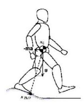
The algorithm used is based on a hybrid approach: linearized inverted pendulum equations and cubic polynomials. The hip and the two feet have individual paths in the 3 dimensions; an inverse kinematic algorithm returns the corresponding angles in the joint space.
Some movements, as for example the advance of the hip when walking straight, are regulated by the usual formula of the inverted pendulum:
$$\ddot{x} = -\frac{x}{z}g$$
Where x is the horizontal distance between the Zero Moment Point (ZMP) and the Center of Mass (CoM), z is the vertical distance, and g the gravity coefficient.
This formula can be analytically solved or integrated in real time: in the first case, the result is a trajectory made of arc of exponentials.
$$x(t) = Ae^t + Be^{-t}$$
Where A e B are constant that can be easily obtained using the velocity and position at t=0. Other paths, as the swing movement of the hip in the frontal plane, are obtained from a simple interpolation of second order. It is known that trajectories that can look smooth and aesthetically similar to human ones, generally are not compatible with the Zero Moment Point constraints that determine the equilibrium of a biped. For these reason a real time algorithm validates the acceleration of the path and adds or modify points of interpolation to the path to satisfy such constraints on $\ddot{x}$.
The team is currently working on the correct integration of the sensors information in the correction of the walking paths. In this way the robot should exhibit more robustness in case of external forces or rough terrain.
The behavior of the robot is regulated by a finite state machine (FSM). The FSM are generated by our own framework, which was designed to be as flexible as possible. The states (i.e. actions) can be sequential or concurrent, and the end of a state and the beginning of the following one is determined by a certain time of delay or can be triggered by external events.
3.3 Color segmentation
Our vision software is able to detect color region and using the stereo information also the distance of different objects in the field of view of the camera. To subsequently increase the speed of the algorithm we use a library accelerated by hardware using special SSE instructions of the Intel processor.
Our color segmentation is based on a double threshold: first a nearly "pure" color is segmented, than contiguous regions with larger and more "permissive" threshold are merged to the segmented object.
In this way we have a more robust detection in structured environment were the objects to recognize have just one color, as the ball or the landmarks.
The Hough transformation is used to detect the white line of the pitch and triangulate the position of the robot.
4 Conclusions
A new humanoid robot has been presented. Arabot is still at his prototype stage, but it is displaying already a very good manipulation skill and interesting walking velocity.
The most interesting feature of the robot is its lightweight, achieved through accurate design and FEM analysis. The best components available commercially were used.
References
- K. Kaneko, F. Kaneiro, S. Kajita, H. Hirukawa, T. Kawasaki, M. Hirata, K. Akachi, T. Isozumi, "Humanoid robot HRP-2", Proceedings of the 2004 IEEE Int. Conference on Robotics & Automation.
- M. Hirose, Y. Haikawa, T. Takenaka, and K, Hirai, "Development of Humanoid Robot ASIMO", Proceedings IEEE/RSJ Int. Conference on Intelligent Robots and Systems, Workshop2 (Oct. 29, 2001), 2001.
- Jung-Yup Kim, Ill-Woo Park, Jungho Lee, Min-Su Kim, Baek-kyu Cho and Jun-Ho Oh, "System design and dynamic walking of humanoid robot KHR-2", Proceedings of the 2005 IEEE Int. Conference on Robotics & Automation.
- T. Morita, H. Iwata, S. Sugano, "Development of human symbiotic robot: WENDY", Proceeding of the 1999 IEEE Int. Conference on Robotics & Automation.
- K. Regenstein and R. Dillmann, "Design of an open hardware architecture for the humanoid robot ARMAR", Proceeding Int. Conf. Humanoid Robots, Karlsruhe, Germany, 2003.
- D. Oberkampf, D. DeMenthon and L.S. Davis, "Iterative Pose Estimation using Coplanar Feature Points", CVGIP: Image Understanding, vol. 63, no. 3, May 1996.